Mitsubishi Outlander: DTC U0019, U0141, U0154, U0155, U0164, U0168, U0170, U0171, U0172, U0173, U0175, U0176, U0184, U0195, U0212, U1414, U1415
DTC U0019: Bus Off (CAN-B)
CAUTION
- If the DTC U0019 is set, be sure to diagnose the CAN main bus line.
- When replacing the ECU, always check that the communication circuit is normal.
DTC SET CONDITION
If the CAN-B circuit malfunction occurs, the SRS-ECU sets the DTC U0019.
JUDGMENT CRITERIA
Because of the CAN-B bus circuit malfunction, if SRS-ECU becomes unable to perform the normal data transmission, SRS-ECU determines that an abnormality is present.
TROUBLESHOOTING HINTS
The CAN bus line may be defective
DIAGNOSIS
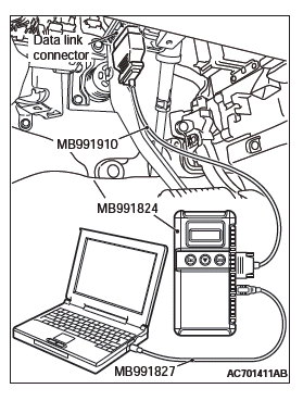
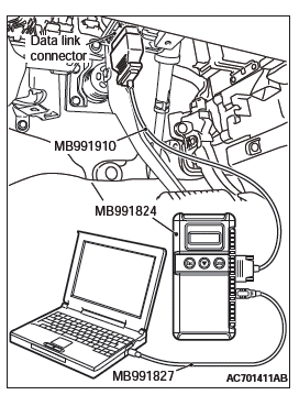
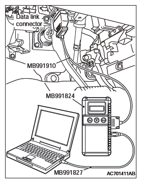
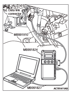
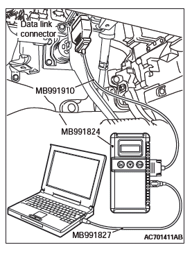
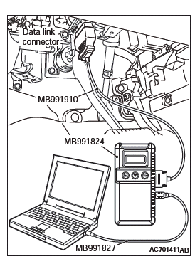
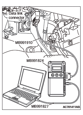
Required Special Tools:
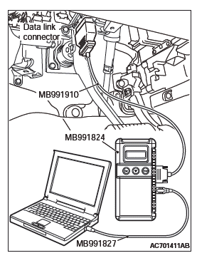
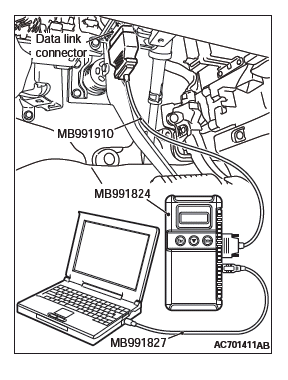
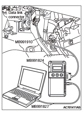
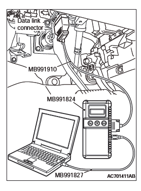
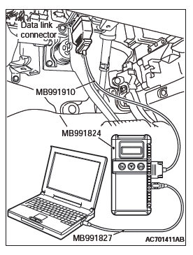
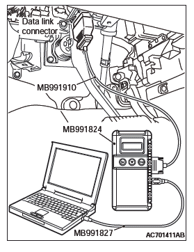
- MB991958: Scan Tool (M.U.T.-III Sub Assembly)
- MB991824: Vehicles Communication Interface (V.C.I.)
- MB991827: M.U.T.-III USB Cable
- MB991910: M.U.T.-III Main Harness A (Vehicles with CAN communication system)
STEP 1. Using scan tool MB991958, diagnose the CAN bus line.
- Turn the ignition switch from "LOCK" (OFF) position to "ON" position.
- Diagnose the CAN bus line.
- Turn the ignition switch to the "LOCK" (OFF) position.
Q: Is the CAN bus line found to be normal?
YES : Go to Step 2.
NO : Repair the CAN bus line.
STEP 2. Recheck for diagnostic trouble code.
Check again if the DTC is set to the SRS-ECU.
CAUTION To prevent damage to scan tool MB991958, always turn the ignition switch to the "LOCK" (OFF) position before connecting or disconnecting scan tool MB991958.

- Connect scan tool MB991958. Refer to "How to connect the scan tool".
- Turn the ignition switch to the "ON" position.
- Check if DTC is set.
- Turn the ignition switch to the "LOCK" (OFF) position.
Q: Is the DTC set?
YES : Replace the SRS-ECU.
NO : The trouble can be an intermittent malfunction.
DTC U0141: ETACS CAN Timeout
CAUTION
- If the DTC U0141 is set, be sure to diagnose the CAN main bus line.
- When replacing the ECU, always check that the communication circuit is normal.
DTC SET CONDITION
If the signal from ETACS-ECU cannot be received, the SRS-ECU sets the DTC U0141.
JUDGMENT CRITERIA
Because of the CAN-B bus circuit malfunction, if SRS-ECU becomes unable to perform the normal data transmission, SRS-ECU determines that an abnormality is present.
TROUBLESHOOTING HINTS
- The CAN bus line may be defective
- The ETACS-ECU may be defective
- The SRS-ECU may be defective
DIAGNOSIS
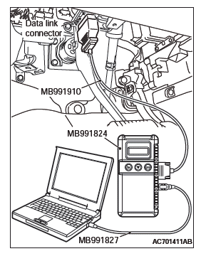
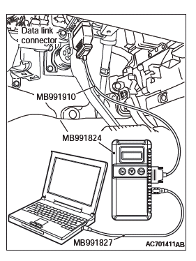
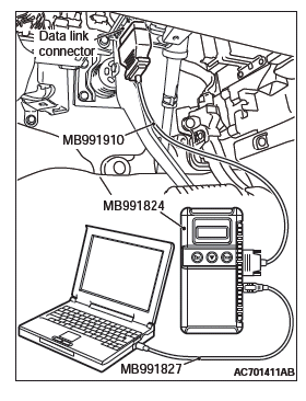
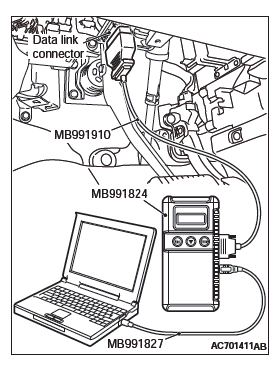
Required Special Tools:
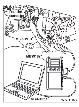
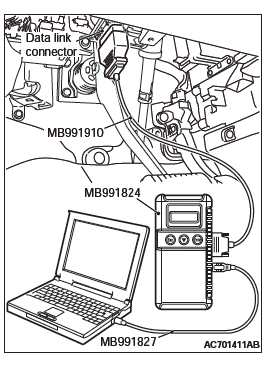
- MB991958: Scan Tool (M.U.T.-III Sub Assembly)
- MB991824: Vehicles Communication Interface (V.C.I.)
- MB991827: M.U.T.-III USB Cable
- MB991910: M.U.T.-III Main Harness A (Vehicles with CAN communication system)
STEP 1. Using scan tool MB991958, diagnose the CAN bus line.
CAUTION To prevent damage to scan tool MB991958, always turn the ignition switch to the "LOCK" (OFF) position before connecting or disconnecting scan tool MB991958.
- Connect scan tool MB991958. Refer to "How to connect the scan tool".
- Turn the ignition switch to the "ON" position.
- Diagnose the CAN bus line.
- Turn the ignition switch to the "LOCK" (OFF) position.
Q: Is the CAN bus line found to be normal?
YES : Go to Step 2.
NO : Repair the CAN bus line.
STEP 2. Using scan tool MB991958, read the ETACS-ECU diagnostic trouble code.
Check again if the DTC is set to the ETACS-ECU.
Q: Is the DTC set?
YES : Diagnose the ETACS-ECU. Then go to Step 4.
NO : Go to Step 3.
STEP 3. Using scan tool MB991958, read diagnostic trouble code No. U0141 for other system.
Check if the DTC U0141 is set in occupant classification-ECU, combination meter, A/C-ECU, KOS-ECU or WCM, hands free module, CAN box unit, radio and CD player, satellite radio tuner.
Q: Is the DTC set?
YES : Replace the ETACS-ECU.
NO : Go to Step 4.
STEP 4 Recheck for diagnostic trouble code.
Check again if the DTC is set to the SRS-ECU.
- Erase the DTC.
- Turn the ignition switch from "LOCK" (OFF) position to "ON" position.
- Check if DTC is set.
- Turn the ignition switch to the "LOCK" (OFF) position.
Q: Is the DTC set?
YES : Replace the SRS-ECU.
NO : There is an intermittent malfunction such as poor engaged connector(s) or open circuit.
DTC U0154: Occupant Classification-ECU CAN Timeout
CAUTION
- If the DTC U0154 is set, be sure to diagnose the CAN main bus line.
- When replacing the ECU, always check that the communication circuit is normal.
DTC SET CONDITION
When the signals from occupant classification-ECU cannot be received, the SRS-ECU sets the DTC U0154.
JUDGMENT CRITERIA
Because of the CAN-B bus circuit malfunction, if SRS-ECU becomes unable to perform the normal data transmission, SRS-ECU determines that an abnormality is present.
TROUBLESHOOTING HINTS
- The CAN bus line may be defective
- The occupant classification-ECU may be defective
- The SRS-ECU may be defective
DIAGNOSIS
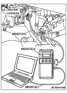
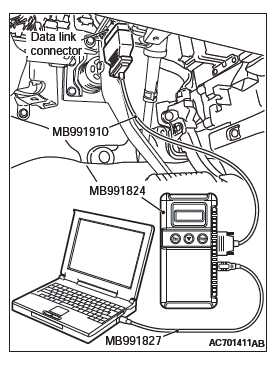
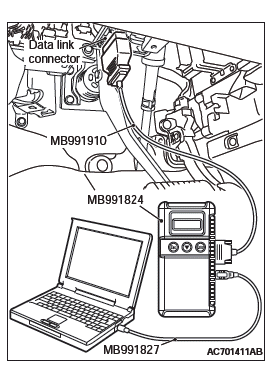
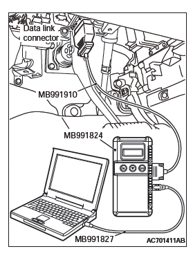
Required Special Tools:
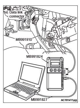
- MB991958: Scan Tool (M.U.T.-III Sub Assembly)
- MB991824: Vehicles Communication Interface (V.C.I.)
- MB991827: M.U.T.-III USB Cable
- MB991910: M.U.T.-III Main Harness A (Vehicles with CAN communication system)
STEP 1. Using scan tool MB991958, diagnose the CAN bus line.
CAUTION To prevent damage to scan tool MB991958, always turn the ignition switch to the "LOCK" (OFF) position before connecting or disconnecting scan tool MB991958.
- Connect scan tool MB991958. Refer to "How to connect the scan tool".
- Turn the ignition switch to the "ON" position.
- Diagnose the CAN bus line.
- Turn the ignition switch to the "LOCK" (OFF) position.
Q: Is the CAN bus line found to be normal?
YES : Go to Step 2.
NO : Repair the CAN bus line.
STEP 2. Using scan tool MB991958, read the occupant classification-ECU diagnostic trouble code.
Check if the DTC is set to the occupant classification-ECU.
Q: Is the DTC B1BAA, B2207, B2208, B2209, B220A, B220B, B220C, B220D or B2255 set?
YES : Carry out troubleshooting of the occupant classification-ECU or the occupant classification sensor system. Then go to Step 4.
NO : Go to Step 3.
STEP 3. Using scan tool MB991958, read diagnostic trouble code No. U0154 for other system.
Check if the DTC U0154 is set in ETACS-ECU, combination meter, A/C-ECU, KOS-ECU or WCM, hands free module, radio and CD player, satellite radio tuner.
Q: Is the DTC set?
YES : Replace the passenger seat cushion frame assembly.
NO : Go to Step 4.
STEP 4. Recheck for diagnostic trouble code.
Check again if the DTC is set to the SRS-ECU.
- Erase the DTC.
- Turn the ignition switch from "LOCK" (OFF) position to "ON" position.
- Check if DTC is set.
- Turn the ignition switch to the "LOCK" (OFF) position.
Q: Is the DTC set?
YES : Replace the SRS-ECU.
NO : There is an intermittent malfunction such as poor engaged connector(s) or open circuit.
DTC U0155: Combination Meter CAN Timeout
CAUTION
- If the DTC U0155 is set, be sure to diagnose the CAN main bus line.
- When replacing the ECU, always check that the communication circuit is normal.
DTC SET CONDITION
If the signal from combination meter cannot be received, the SRS-ECU sets the DTC U0155.
JUDGMENT CRITERIA
Because of the CAN-B bus circuit malfunction, if SRS-ECU becomes unable to perform the normal data transmission, SRS-ECU determines that an abnormality is present.
TROUBLESHOOTING HINTS
- The CAN bus line may be defective
- The combination meter may be defective
- The SRS-ECU may be defective
DIAGNOSIS
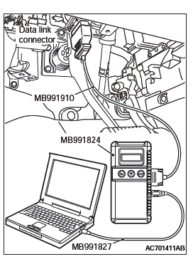
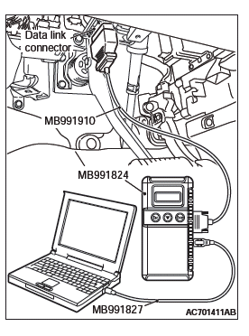
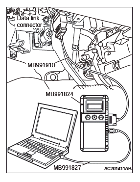
Required Special Tools:
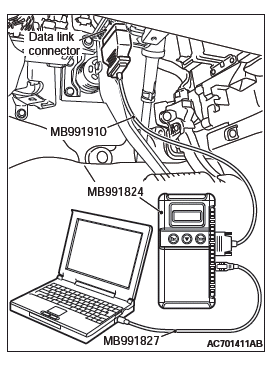
- MB991958: Scan Tool (M.U.T.-III Sub Assembly)
- MB991824: Vehicles Communication Interface (V.C.I.)
- MB991827: M.U.T.-III USB Cable
- MB991910: M.U.T.-III Main Harness A (Vehicles with CAN communication system)
STEP 1. Using scan tool MB991958, diagnose the CAN bus line.
CAUTION To prevent damage to scan tool MB991958, always turn the ignition switch to the "LOCK" (OFF) position before connecting or disconnecting scan tool MB991958.
- Connect scan tool MB991958. Refer to "How to connect the scan tool".
- Turn the ignition switch to the "ON" position.
- Diagnose the CAN bus line.
- Turn the ignition switch to the "LOCK" (OFF) position.
Q: Is the CAN bus line found to be normal?
YES : Go to Step 2.
NO : Repair the CAN bus line.
STEP 2. Using scan tool MB991958, read the combination meter diagnostic trouble code.
Check if DTC is set to the combination meter.
Q: Is the DTC set?
YES : Diagnose the combination meter. Then go to Step 4.
NO : Go to Step 3.
STEP 3. Using scan tool MB991958, read diagnostic trouble code No. U0155 for other system.
Check if the DTC U0155 is set in ETACS-ECU, occupant classification- ECU, A/C-ECU, KOS-ECU or WCM, hands free module, CAN box unit, radio and CD player, satellite radio tuner.
Q: Is the DTC set?
YES : Replace the combination meter.
NO : Go to Step 4.
STEP 4. Recheck for diagnostic trouble code.
Check again if the DTC is set to the SRS-ECU.
- Erase the DTC.
- Turn the ignition switch from "LOCK" (OFF) position to "ON" position.
- Check if DTC is set.
- Turn the ignition switch to the "LOCK" (OFF) position.
Q: Is the DTC set?
YES : Replace the SRS-ECU.
NO : There is an intermittent malfunction such as poor engaged connector(s) or open circuit (Refer to GROUP 00, How to use Troubleshooting/inspection Service Points).
DTC U0164: A/C-ECU CAN Timeout
CAUTION
- If the DTC U0164 is set, be sure to diagnose the CAN main bus line.
- When replacing the ECU, always check that the communication circuit is normal.
DTC SET CONDITION
If the signal from A/C-ECU cannot be received, the SRS-ECU sets the DTC U0164.
JUDGMENT CRITERIA
Because of the CAN-B bus circuit malfunction, if SRS-ECU becomes unable to perform the normal data transmission, SRS-ECU determines that an abnormality is present.
TROUBLESHOOTING HINTS
- The CAN bus line may be defective
- The A/C-ECU may be defective
- The SRS-ECU may be defective
DIAGNOSIS
Required Special Tools:
- MB991958: Scan Tool (M.U.T.-III Sub Assembly)
- MB991824: Vehicles Communication Interface (V.C.I.)
- MB991827: M.U.T.-III USB Cable
- MB991910: M.U.T.-III Main Harness A (Vehicles with CAN communication system)
STEP 1. Using scan tool MB991958, diagnose the CAN bus line.
CAUTION To prevent damage to scan tool MB991958, always turn the ignition switch to the "LOCK" (OFF) position before connecting or disconnecting scan tool MB991958.
- Connect scan tool MB991958. Refer to "How to connect the Scan Tool (M.U.T.-III)".
- Turn the ignition switch to the "ON" position.
- Diagnose the CAN bus line.
- Turn the ignition switch to the "LOCK" (OFF) position.
Q: Is the CAN bus line found to be normal?
YES : Go to Step 2.
NO : Repair the CAN bus line.
STEP 2. Using scan tool MB991958, read the A/C diagnostic trouble code.
Check if DTC is set to the A/C-ECU.
Q: Is the DTC set?
YES : Diagnose the A/C. Then go to Step 4.
NO : Go to Step 3.
STEP 3. Using scan tool MB991958, read diagnostic trouble code No. U0164 for other system.
Check if the DTC U0164 is set in ETACS-ECU, occupant classification- ECU, combination meter, KOS-ECU or WCM, hands free module, CAN box unit, radio and CD player, satellite radio tuner.
Q: Is the DTC set?
YES : Replace the A/C-ECU.
NO : Go to Step 4.
STEP 4. Recheck for diagnostic trouble code.
Check again if the DTC is set to the SRS-ECU.
- Erase the DTC.
- Turn the ignition switch from "LOCK" (OFF) position to "ON" position.
- Check if DTC is set.
- Turn the ignition switch to the "LOCK" (OFF) position.
Q: Is the DTC set?
YES : Replace the SRS-ECU.
NO : There is an intermittent malfunction such as poor engaged connector(s) or open circuit.
DTC U0168: KOS-ECU or WCM CAN Timeout
CAUTION
- If DTC U0168 is set, be sure to diagnose the CAN bus line.
- When replacing the ECU, always check that the communication circuit is normal.
DTC SET CONDITION
If the signal from KOS-ECU or WCM cannot be received, the SRS-ECU sets the DTC U0168.
JUDGMENT CRITERIA
Because of the CAN-B bus circuit malfunction, if SRS-ECU becomes unable to perform the normal data transmission, SRS-ECU determines that an abnormality is present.
TROUBLESHOOTING HINTS
- Malfunction of CAN bus line may be defective.
- Malfunction of the KOS-ECU may be defective.
- Malfunction of the WCM may be defective.
- Malfunction of SRS-ECU may be defective.
DIAGNOSIS
Required Special Tools:
- MB991958: Scan Tool (M.U.T.-III Sub Assembly)
- MB991824: Vehicles Communication Interface (V.C.I.)
- MB991827: M.U.T.-III USB Cable
- MB991910: M.U.T.-III Main Harness A (Vehicles with CAN communication system)
STEP 1. Using scan tool MB991958, diagnose the CAN bus line.
CAUTION To prevent damage to scan tool MB991958, always turn the ignition switch to the "LOCK" (OFF) position before connecting or disconnecting scan tool MB991958.
- Connect scan tool MB991958. Refer to "How to connect the Scan Tool (M.U.T.-III)".
- Turn the ignition switch to the "ON" position.
- Diagnose the CAN bus line.
- Turn the ignition switch to the "LOCK" (OFF) position.
Q: Is the CAN bus line found to be normal?
YES : Go to Step 2.
NO : Repair the CAN bus line.
STEP 2. Using scan tool MB991958, read the KOS-ECU or WCM diagnostic trouble code.
Check again if the DTC is set to the KOS-ECU or WCM.
Q: Is the DTC set?
YES : Diagnose the KOS or WCM.
Then go to Step 4.
NO : Go to Step 3.
STEP 3. Using scan tool MB991958, read diagnostic trouble code No. U0168 for other system.
Check if the DTC U0168 is set in ETACS-ECU, occupant classification- ECU, combination meter, A/C-ECU, hands free module, CAN box unit, radio and CD player, satellite radio tuner.
Q: Is the DTC set?
YES : Replace the KOS -ECU or WCM
NO : Go to Step 4.
STEP 4. Recheck for diagnostic trouble code.
Check again if the DTC is set to the SRS-ECU.
- Erase the DTC.
- Turn the ignition switch from "LOCK" (OFF) position to "ON" position.
- Check if DTC is set.
- Turn the ignition switch to the "LOCK" (OFF) position.
Q: Is the DTC set?
YES : Replace the SRS-ECU.
NO : There is an intermittent malfunction such as poor engaged connector(s) or open circuit.
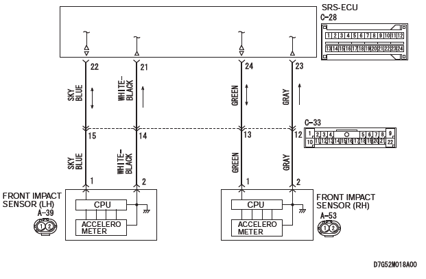
DTC U0170: Front Impact Sensor (LH) Communication Error
Front Impact Sensor Circuit
CAUTION If DTC U0170 is set in the SRS-ECU, always diagnose the CAN main bus line.
CIRCUIT OPERATION
If an impact of set value or more is detected, the front impact sensor sends the coded acceleration data to SRS-ECU. Based on the acceleration data, SRS-ECU determines the necessity of driver's and front passenger's air bag deployment, and then turns ON the power supply circuit to the inflator.
DTC SET CONDITIONS
These DTCs are set if communication between the front impact sensor (LH) and the SRS-ECU is not possible or faulty.
TROUBLESHOOTING HINTS
- Damaged wiring harnesses or connectors
- Malfunction of the front impact sensor (LH)
- Malfunction of the SRS-ECU
DIAGNOSIS
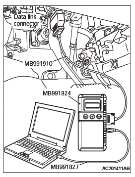
Required Special Tools:
- MB991958: Scan Tool (M.U.T.-III Sub Assembly)
- MB991824: Vehicle Communication Interface (V.C.I.)
- MB991827: M.U.T.-III USB Cable
- MB991910: M.U.T.-III Main Harness A (Vehicles with CAN communication system)
STEP 1. Using scan tool MB991958, diagnose the CAN bus line.
CAUTION To prevent damage to scan tool MB991958, always turn the ignition switch to the "LOCK" (OFF) position before connecting or disconnecting scan tool MB991958.
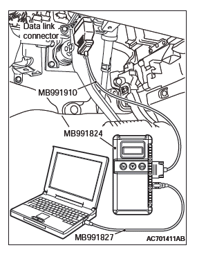
- Connect scan tool MB991958. Refer to "How to connect the scan tool".
- Turn the ignition switch to the "ON" position.
- Diagnose the CAN bus line.
- Turn the ignition switch to the "LOCK" (OFF) position.
Q: Is the CAN bus line found to be normal?
YES : Go to Step 2.
NO : Repair the CAN bus line.
STEP 2. Recheck for diagnostic trouble code.
Check again if the DTC is set.
- Erase the DTC.
- Turn the ignition switch to the "ON" position.
- Check if the DTC is set.
- Turn the ignition switch to the "LOCK" (OFF) position.
Q: Is the DTC set?
YES : Go to Step 3.
NO : There is an intermittent malfunction such as poor engaged connector(s) or open circuit.
STEP 3. Check for any diagnostic trouble code. (Using scan tool MB991958, read the diagnostic trouble code.)
Check the front impact sensor (LH).
- Disconnect the negative battery terminal.
- Alternate the front impact sensor (LH) and front impact sensor (RH), and then install the alternated sensors.
- Connect the negative battery terminal.
- Erase diagnostic trouble code from memory, and check the diagnostic trouble code.
Q: Is DTC U0171 set?
YES : Replace the front impact sensor (LH) with a new one.
Go to Step 5.
NO : Go to Step 4.
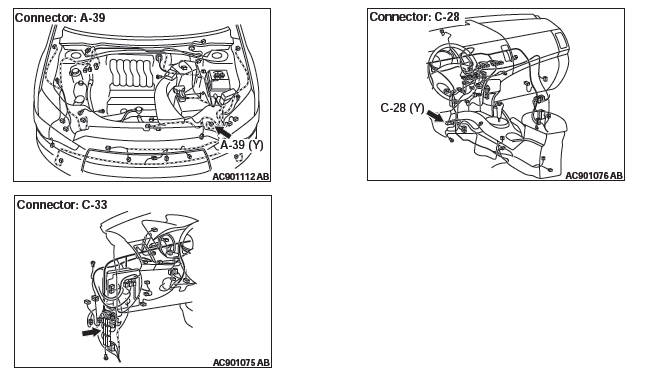
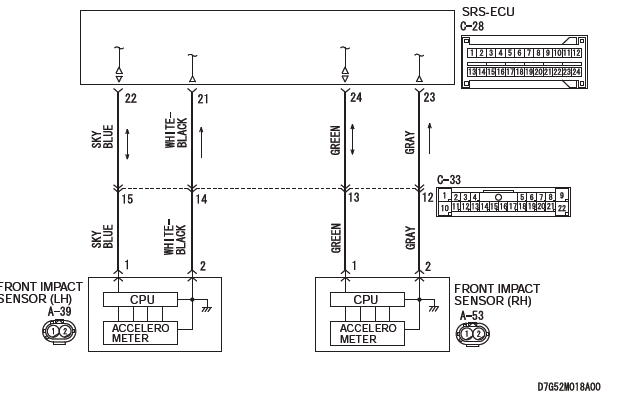
STEP 4. Check the harness wires for open circuit and short circuit between SRS-ECU connector C-28 (terminal No.21 and 22) and front impact sensor (LH) connector A-39 (terminal No.2 and 1).
NOTE: After inspecting intermediate connector C-33 inspect the wiring harness. If the intermediate connector C-33 is damaged, repair or replace it.
Q: Are the harness wires between SRS-ECU connector C-28 (terminal No.21 and 22) and front impact sensor (LH) connector A-39 (terminal No.2 and 1) in good condition?
YES : Go to Step 5.
NO : Repair the harness wires between SRS-ECU connector C-28 and front impact sensor (LH) connector A-39.
STEP 5. Recheck for diagnostic trouble code.
Check again if the DTC is set.
- Erase the DTC.
- Turn the ignition switch to the "ON" position.
- Check if the DTC is set.
- Turn the ignition switch to the "LOCK" (OFF) position.
Q: Is DTC U0170 set?
YES : Replace SRS-ECU.
NO : There is an intermittent malfunction such as poor engaged connector(s) or open circuit.
DTC U0171: Front Impact Sensor (RH) Communication Error
Front Impact Sensor Circuit

CAUTION If DTC U0171 is set in the SRS-ECU, always diagnose the CAN main bus line.
CIRCUIT OPERATION
If an impact of set value or more is detected, the front impact sensor sends the coded acceleration data to SRS-ECU. Based on the acceleration data, SRS-ECU determines the necessity of driver's and front passenger's air bag deployment, and then turns ON the power supply circuit to the inflator.
DTC SET CONDITIONS
These DTCs are set if communication between the front impact sensor (RH) and the SRS-ECU is not possible or faulty.
TROUBLESHOOTING HINTS
- Damaged wiring harnesses or connectors
- Malfunction of the front impact sensor (RH)
- Malfunction of the SRS-ECU
DIAGNOSIS
Required Special Tools:
- MB991958: Scan Tool (M.U.T.-III Sub Assembly)
- MB991824: Vehicle Communication Interface (V.C.I.)
- MB991827: M.U.T.-III USB Cable
- MB991910: M.U.T.-III Main Harness A (Vehicles with CAN communication system)
STEP 1. Using scan tool MB991958, diagnose the CAN bus line.
CAUTION To prevent damage to scan tool MB991958, always turn the ignition switch to the "LOCK" (OFF) position before connecting or disconnecting scan tool MB991958.
- Connect scan tool MB991958. Refer to "How to connect the scan tool".
- Turn the ignition switch to the "ON" position.
- Diagnose the CAN bus line.
- Turn the ignition switch to the "LOCK" (OFF) position.
Q: Is the CAN bus line found to be normal?
YES : Go to Step 2.
NO : Repair the CAN bus line.
STEP 2. Recheck for diagnostic trouble code.
Check again if the DTC is set.

- Erase the DTC.
- Turn the ignition switch to the "ON" position.
- Check if the DTC is set.
- Turn the ignition switch to the "LOCK" (OFF) position.
Q: Is the DTC set?
YES : Go to Step 3.
NO : There is an intermittent malfunction such as poor engaged connector(s) or open circuit.
STEP 3. Check for any diagnostic trouble code. (Using scan tool MB991958, read the diagnostic trouble code.)
Check the front impact sensor (RH).
- Disconnect the negative battery terminal.
- Alternate the front impact sensor (RH) and front impact sensor (LH), and then install the alternated sensors.
- Connect the negative battery terminal.
- Erase diagnostic trouble code from memory, and check the diagnostic trouble code.
Q: Is DTC U0170 set?
YES : Replace the front impact sensor (RH) with a new one. Go to Step 5.
NO : Go to Step 4.
STEP 4. Check the harness wires for open circuit and short circuit between SRS-ECU connector C-28 (terminal No.23 and 24) and front impact sensor (RH) connector A-53 (terminal No.2 and 1).
NOTE: After inspecting intermediate connector C-33 inspect the wiring harness. If the intermediate connector C-33 is damaged, repair or replace it.
Q: Are the harness wires between SRS-ECU connector C-28 (terminal No.23 and 24) and front impact sensor (RH) connector A-53 (terminal No.2 and 1) in good condition?
YES : Go to Step 5.
NO : Repair the harness wires between SRS-ECU connector C-28 and front impact sensor (RH) connector A-53.
STEP 5. Recheck for diagnostic trouble code.
Check again if the DTC is set.
- Erase the DTC.
- Turn the ignition switch to the "ON" position.
- Check if the DTC is set.
- Turn the ignition switch to the "LOCK" (OFF) position.
Q: Is DTC U0171 set?
YES : Replace the SRS-ECU.
NO : There is an intermittent malfunction such as poor engaged connector(s) or open circuit.
DTC U0172: Side Impact Sensor (Front) (LH) Communication Error
Side Impact Sensor (Front, Rear) (LH) Circuit
CAUTION If DTC U0172 is set in the SRS-ECU, always diagnose the CAN main bus line.
CIRCUIT OPERATION
If an impact of set value or more is detected, the side impact sensor sends the coded acceleration data to SRS-ECU. Based on the acceleration data, SRS-ECU determines the necessity of side-air bag and curtain air bag deployment, and then turns ON the power supply circuit to the inflator.
DTC SET CONDITIONS
These DTCs are set if communication between the side impact sensor (front) (LH) and the SRS-ECU is not possible or faulty.
TROUBLESHOOTING HINTS
- Damaged wiring harnesses or connectors
- Malfunction of the side impact sensor (front) (LH)
- Malfunction of the SRS-ECU
DIAGNOSIS
Required Special Tools:
- MB991958: Scan Tool (M.U.T.-III Sub Assembly)
- MB991824: Vehicle Communication Interface (V.C.I.)
- MB991827: M.U.T.-III USB Cable
- MB991910: M.U.T.-III Main Harness A (Vehicles with CAN communication system)
STEP 1. Using scan tool MB991958, diagnose the CAN bus line.
CAUTION To prevent damage to scan tool MB991958, always turn the ignition switch to the "LOCK" (OFF) position before connecting or disconnecting scan tool MB991958.
- Connect scan tool MB991958. Refer to "How to connect the scan tool".
- Turn the ignition switch to the "ON" position.
- Diagnose the CAN bus line.
- Turn the ignition switch to the "LOCK" (OFF) position.
Q: Is the CAN bus line found to be normal?
YES : Go to Step 2.
NO : Repair the CAN bus line.
STEP 2. Recheck for diagnostic trouble code.
Check again if the DTC is set.
- Erase the DTC.
- Turn the ignition switch to the "ON" position.
- Check if the DTC is set.
- Turn the ignition switch to the "LOCK" (OFF) position.
Q: Is the DTC set?
YES : Go to Step 3.
NO : There is an intermittent malfunction such as poor engaged connector(s) or open circuit.
STEP 3. Check for any diagnostic trouble code. (Using scan tool MB991958, read the diagnostic trouble code.)
Check the side impact sensor (front) (LH).
- Disconnect the negative battery terminal.
- Alternate the side impact sensor (front) (LH) and side impact sensor (front) (RH), and then install the alternated sensors.
- Connect the negative battery terminal.
- Erase diagnostic trouble code from memory, and check the diagnostic trouble code.
Q: Is DTC U0175 set?
YES : Replace the side impact sensor (front) (LH) with a new one. Go to Step 5.
NO : Go to Step 4.
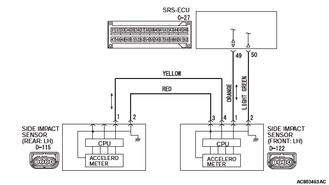
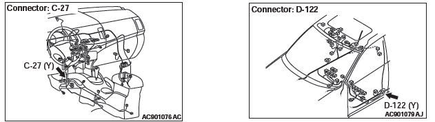
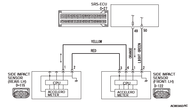
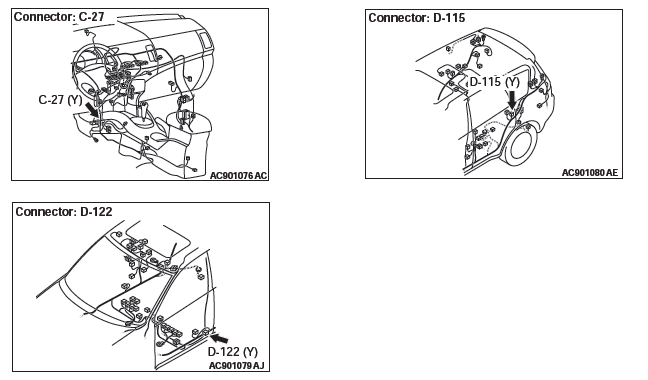
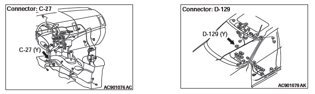
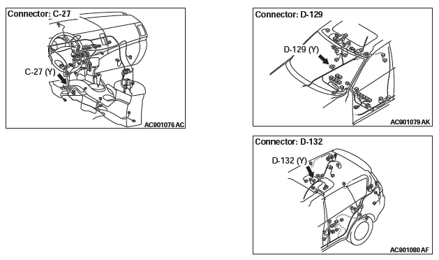
STEP 4. Check the harness wires for open circuit and short circuit between SRS-ECU connector C-27 (terminal No.49 and 50) and side impact sensor (front) (LH) connector D-122 (terminal No.1 and 2).
Q: Are the harness wires between SRS-ECU connector C-27 (terminal No.49 and 50) and side impact sensor (front) (LH) connector D-122 (terminal No.1 and 2) in good condition?
YES : Go to Step 5.
NO : Repair the harness wires between SRS-ECU connector C-27 and side impact sensor (front) (LH) connector D-122.
STEP 5. Recheck for diagnostic trouble code.
Check again if the DTC is set.
- Erase the DTC.
- Turn the ignition switch to the "ON" position.
- Check if the DTC is set.
- Turn the ignition switch to the "LOCK" (OFF) position.
Q: Is DTC U0172 set?
YES : Replace the SRS-ECU.
NO : There is an intermittent malfunction such as poor engaged connector(s) or open circuit.
DTC U0173: Side Impact Sensor (Rear) (LH) Communication Error
Side Impact Sensor (Front, Rear) (LH) Circuit
CAUTION If DTC U0173 is set in the SRS-ECU, always diagnose the CAN main bus line.
CIRCUIT OPERATION
If an impact of set value or more is detected, the side impact sensor (rear) sends the coded acceleration data to SRS-ECU via side impact sensor (front).
Based on the acceleration data, SRS-ECU determines the necessity of curtain air bag deployment, and then turns ON the power supply circuit to the inflator.
DTC SET CONDITIONS
These DTCs are set if communication between the side impact sensor (rear) (LH) and the SRS-ECU is not possible or faulty.
TROUBLESHOOTING HINTS
- Damaged wiring harnesses or connectors
- Malfunction of the side impact sensor (rear) (LH)
- Malfunction of the SRS-ECU
DIAGNOSIS
Required Special Tools:
- MB991958: Scan Tool (M.U.T.-III Sub Assembly)
- MB991824: Vehicle Communication Interface (V.C.I.)
- MB991827: M.U.T.-III USB Cable
- MB991910: M.U.T.-III Main Harness A (Vehicles with CAN communication system)
STEP 1. Using scan tool MB991958, diagnose the CAN bus line.
CAUTION To prevent damage to scan tool MB991958, always turn the ignition switch to the "LOCK" (OFF) position before connecting or disconnecting scan tool MB991958.
- Connect scan tool MB991958. Refer to "How to connect the scan tool".
- Turn the ignition switch to the "ON" position.
- Diagnose the CAN bus line.
- Turn the ignition switch to the "LOCK" (OFF) position.
Q: Is the CAN bus line found to be normal?
YES : Go to Step 2.
NO : Repair the CAN bus line.
STEP 2. Recheck for diagnostic trouble code.
Check again if the DTC is set.
- Erase the DTC.
- Turn the ignition switch to the "ON" position.
- Check if the DTC is set.
- Turn the ignition switch to the "LOCK" (OFF) position.
Q: Is the DTC set?
YES : Go to Step 3.
NO : There is an intermittent malfunction such as poor engaged connector(s) or open circuit (Refer to GROUP 00, How to Cope with Intermittent Malfunction).
STEP 3. Check for any diagnostic trouble code. (Using scan tool MB991958, read the diagnostic trouble code.)
Check the side impact sensor (rear) (LH).
- Disconnect the negative battery terminal.
- Alternate the side impact sensor (rear) (LH) and side impact sensor (rear) (RH), and then install the alternated sensors.
- Connect the negative battery terminal.
- Erase diagnostic trouble code from memory, and check the diagnostic trouble code.
Q: Is DTC U0176 set?
YES : Replace the side impact sensor (rear) (LH) with a new one. Go to Step 5.
NO : Go to Step 4.
STEP 4. Check the harness wires for open circuit and short circuit between side impact sensor (rear) (LH) connector D-115 (terminal No.1 and 2) and side impact sensor (front) (LH) connector D-122 (terminal No.4 and 3).
Q: Are the harness wires between side impact sensor (rear) (LH) connector D-115 (terminal No.1 and 2) and side impact sensor (front) (LH) connector D-122 (terminal No.4 and 3) in good condition?
YES : Go to Step 5.
NO : Repair the harness wires between side impact sensor (rear) (LH) connector D-115 and side impact sensor (front) (LH) connector D-122.
STEP 5. Recheck for diagnostic trouble code.
Check again if the DTC is set.
- Erase the DTC.
- Turn the ignition switch to the "ON" position.
- Check if the DTC is set.
- Turn the ignition switch to the "LOCK" (OFF) position.
Q: Is DTC U0173 set?
YES : Replace the SRS-ECU.
NO : There is an intermittent malfunction such as poor engaged connector(s) or open circuit.
DTC U0175: Side Impact Sensor (Front) (RH) Communication Error
Side Impact Sensor (Front, Rear) (RH) Circuit
CAUTION If DTC U0175 is set in the SRS-ECU, always diagnose the CAN main bus line.
CIRCUIT OPERATION
If an impact of set value or more is detected, the side impact sensor sends the coded acceleration data to SRS-ECU. Based on the acceleration data, SRS-ECU determines the necessity of side air bag and curtain air bag deployment, and then turns ON the power supply circuit to the inflator.
DTC SET CONDITIONS
These DTCs are set if communication between the side impact sensor (front) (RH) and the SRS-ECU is not possible or faulty.
TROUBLESHOOTING HINTS
- Damaged wiring harnesses or connectors
- Malfunction of the side impact sensor (front) (RH)
- Malfunction of the SRS-ECU
DIAGNOSIS
Required Special Tools:
- MB991958: Scan Tool (M.U.T.-III Sub Assembly)
- MB991824: Vehicle Communication Interface (V.C.I.)
- MB991827: M.U.T.-III USB Cable
- MB991910: M.U.T.-III Main Harness A (Vehicles with CAN communication system)
STEP 1. Using scan tool MB991958, diagnose the CAN bus line.
CAUTION To prevent damage to scan tool MB991958, always turn the ignition switch to the "LOCK" (OFF) position before connecting or disconnecting scan tool MB991958.
- Connect scan tool MB991958. Refer to "How to connect the scan tool".
- Turn the ignition switch to the "ON" position.
- Diagnose the CAN bus line.
- Turn the ignition switch to the "LOCK" (OFF) position.
Q: Is the CAN bus line found to be normal?
YES : Go to Step 2.
NO : Repair the CAN bus line.
STEP 2. Recheck for diagnostic trouble code.
Check again if the DTC is set.
- Erase the DTC.
- Turn the ignition switch to the "ON" position.
- Check if the DTC is set.
- Turn the ignition switch to the "LOCK" (OFF) position.
Q: Is the DTC set?
YES : Go to Step 3.
NO : There is an intermittent malfunction such as poor engaged connector(s) or open circuit (Refer to GROUP 00, How to Cope with Intermittent Malfunction).
STEP 3. Check for any diagnostic trouble code. (Using scan tool MB991958, read the diagnostic trouble code.)
Check the side impact sensor (front) (RH).
- Disconnect the negative battery terminal.
- Alternate the side impact sensor (front) (RH) and side impact sensor (front) (LH), and then install the alternated sensors.
- Connect the negative battery terminal.
- Erase diagnostic trouble code from memory, and check the diagnostic trouble code.
Q: Is DTC U0172 set?
YES : Replace the side impact sensor (front) (RH) with a new one. Go to Step 5.
NO : Go to Step 4.
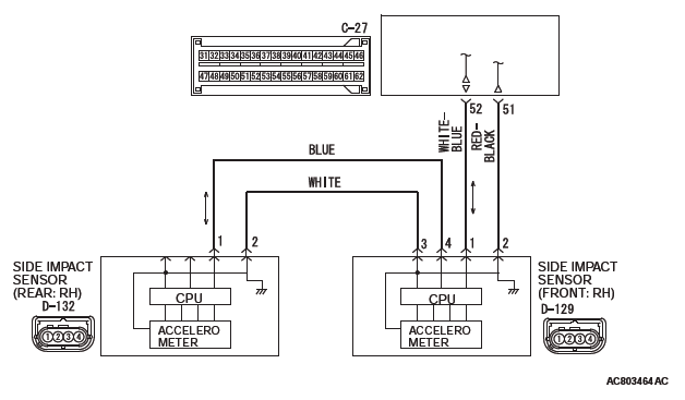
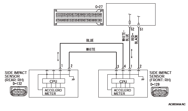
STEP 4. Check the harness wires for open circuit and short circuit between SRS-ECU connector C-27 (terminal No.51 and 52) and side impact sensor (front) (RH) connector D-129 (terminal No.2 and 1).
Q: Are the harness wires between SRS-ECU connector C-27 (terminal No.51 and 52) and side impact sensor (front) (RH) connector D-129 (terminal No.2 and 1) in good condition?
YES : Go to Step 5.
NO : Repair the harness wires between SRS-ECU connector C-27 and side impact sensor (front) (RH) connector D-129.
STEP 5. Recheck for diagnostic trouble code.
Check again if the DTC is set.
- Erase the DTC.
- Turn the ignition switch to the "ON" position.
- Check if the DTC is set.
- Turn the ignition switch to the "LOCK" (OFF) position.
Q: Is DTC U0175 set?
YES : Replace the SRS-ECU.
NO : There is an intermittent malfunction such as poor engaged connector(s) or open circuit (Refer to GROUP 00, How to Cope with Intermittent Malfunction).
DTC U0176: Side Impact Sensor (Rear) (RH) Communication Error
Side Impact Sensor (Front, Rear) (RH) Circuit
CAUTION If DTC U0176 is set in the SRS-ECU, always diagnose the CAN main bus line.
CIRCUIT OPERATION
If an impact of set value or more is detected, the side impact sensor (rear) sends the coded acceleration data to SRS-ECU via side impact sensor (front).
Based on the acceleration data, SRS-ECU determines the necessity of curtain air bag deployment, and then turns ON the power supply circuit to the inflator.
DTC SET CONDITIONS
These DTCs are set if communication between the side impact sensor (rear) (RH) and the SRS-ECU is not possible or faulty.
TROUBLESHOOTING HINTS
- Damaged wiring harnesses or connectors
- Malfunction of the side impact sensor (rear) (RH)
- Malfunction of the SRS-ECU
DIAGNOSIS
Required Special Tools:
- MB991958: Scan Tool (M.U.T.-III Sub Assembly)
- MB991824: Vehicle Communication Interface (V.C.I.)
- MB991827: M.U.T.-III USB Cable
- MB991910: M.U.T.-III Main Harness A (Vehicles with CAN communication system)
STEP 1. Using scan tool MB991958, diagnose the CAN bus line.
CAUTION To prevent damage to scan tool MB991958, always turn the ignition switch to the "LOCK" (OFF) position before connecting or disconnecting scan tool MB991958.
- Connect scan tool MB991958. Refer to "How to connect the scan tool".
- Turn the ignition switch to the "ON" position.
- Diagnose the CAN bus line.
- Turn the ignition switch to the "LOCK" (OFF) position.
Q: Is the CAN bus line found to be normal?
YES : Go to Step 2.
NO : Repair the CAN bus line.
STEP 2. Recheck for diagnostic trouble code.
Check again if the DTC is set.
- Erase the DTC.
- Turn the ignition switch to the "ON" position.
- Check if the DTC is set.
- Turn the ignition switch to the "LOCK" (OFF) position.
Q: Is the DTC set?
YES : Go to Step 3.
NO : There is an intermittent malfunction such as poor engaged connector(s) or open circuit (Refer to GROUP 00, How to Cope with Intermittent Malfunction).
STEP 3. Check for any diagnostic trouble code. (Using scan tool MB991958, read the diagnostic trouble code.) Check the side impact sensor (rear) (RH).
- Disconnect the negative battery terminal.
- Alternate the side impact sensor (rear) (RH) and side impact sensor (rear) (LH), and then install the alternated sensors.
- Connect the negative battery terminal.
- Erase diagnostic trouble code from memory, and check the diagnostic trouble code.
Q: Is DTC U0173 set?
YES : Replace the side impact sensor (rear) (RH) with a new one. Go to Step 5.
NO : Go to Step 4.
STEP 4. Check the harness wires for open circuit and short circuit between side impact sensor (rear) (RH) connector D-132 (terminal No.1 and 2) and side impact sensor (front) (RH) connector D-129 (terminal No.4 and 3).
Q: Are the harness wires between side impact sensor (rear) (RH) connector D-132 (terminal No.1 and 2) and side impact sensor (front) (RH) connector D-129 (terminal No.4 and 3) in good condition?
YES : Go to Step 5.
NO : Repair the harness wires between side impact sensor (rear) (RH) connector D-132 and side impact sensor (front) (RH) connector D-129.
STEP 5. Recheck for diagnostic trouble code.
Check again if the DTC is set.
- Erase the DTC.
- Turn the ignition switch to the "ON" position.
- Check if the DTC is set.
- Turn the ignition switch to the "LOCK" (OFF) position.
Q: Is DTC U0176 set?
YES : Replace the SRS-ECU.
NO : There is an intermittent malfunction such as poor engaged connector(s) or open circuit (Refer to GROUP 00, How to Cope with Intermittent Malfunction).
DTC U0184: Audio CAN Timeout
CAUTION
- If the DTC U0184 is set, be sure to diagnose the CAN main bus line.
- When replacing the ECU, always check that the communication circuit is normal.
DTC SET CONDITION
When the signals from radio and CD player or CD changer cannot be received, the SRS-ECU sets the DTC U0184.
JUDGMENT CRITERIA
Because of the CAN-B bus circuit malfunction, if SRS-ECU becomes unable to perform the normal data transmission, SRS-ECU determines that an abnormality is present.
TROUBLESHOOTING HINTS
- The CAN bus line may be defective
- The radio and CD player or CD changer may be defective
- The SRS-ECU may be defective
DIAGNOSIS
Required Special Tools:
- MB991958: Scan Tool (M.U.T.-III Sub Assembly)
- MB991824: Vehicles Communication Interface (V.C.I.)
- MB991827: M.U.T.-III USB Cable
- MB991910: M.U.T.-III Main Harness A (Vehicles with CAN communication system)
STEP 1. Using scan tool MB991958, diagnose the CAN bus line.
CAUTION To prevent damage to scan tool MB991958, always turn the ignition switch to the "LOCK" (OFF) position before connecting or disconnecting scan tool MB991958.
- Connect scan tool MB991958. Refer to "How to connect the scan tool".
- Turn the ignition switch to the "ON" position.
- Diagnose the CAN bus line.
- Turn the ignition switch to the "LOCK" (OFF) position.
Q: Is the CAN bus line found to be normal?
YES : Go to Step 2.
NO : Repair the CAN bus line.
STEP 2. Using scan tool MB991958, read the audio diagnostic trouble code.
Check if the DTC is set to the audio.
Q: Is the DTC set?
YES : Diagnose the radio and CD player. Then go to Step 4.
NO : Go to Step 3.
STEP 3. Using scan tool MB991958, read diagnostic trouble code No. U0184 for other system.
Check if the DTC U0184 is set in ETACS-ECU, occupant classification- ECU, combination meter, A/C-ECU, KOS-ECU or WCM, hands free module, satellite radio tuner.
Q: Is the DTC set?
YES : Replace the radio and CD player.
NO : Go to Step 4.
STEP 4. Recheck for diagnostic trouble code.
Check again if the DTC is set to the SRS-ECU.
- Erase the DTC.
- Turn the ignition switch from "LOCK" (OFF) position to "ON" position.
- Check if DTC is set.
- Turn the ignition switch to the "LOCK" (OFF) position.
Q: Is the DTC set?
YES : Replace the SRS-ECU.
NO : There is an intermittent malfunction such as poor engaged connector(s) or open circuit (Refer to GROUP 00, How to use Troubleshooting/inspection Service Points).
DTC U0195: Satellite Radio Tuner CAN Timeout
CAUTION
- If the DTC U0195 is set, be sure to diagnose the CAN main bus line.
- When replacing the ECU, always check that the communication circuit is normal.
DTC SET CONDITION
If the signal from satellite radio tuner cannot be received, the SRS-ECU sets the DTC U0195.
JUDGMENT CRITERIA
Because of the CAN-B bus circuit malfunction, if SRS-ECU becomes unable to perform the normal data transmission, SRS-ECU determines that an abnormality is present.
TROUBLESHOOTING HINTS
- The CAN bus may be defective.
- The satellite radio tuner may be defective.
- The SRS-ECU may be defective.
DIAGNOSIS
Required Special Tools:
- MB991958: Scan Tool (M.U.T.-III Sub Assembly)
- MB991824: Vehicles Communication Interface (V.C.I.)
- MB991827: M.U.T.-III USB Cable
- MB991910: M.U.T.-III Main Harness A (Vehicles with CAN communication system)
STEP 1. Using scan tool MB991958, diagnose the CAN bus line.
CAUTION To prevent damage to scan tool MB991958, always turn the ignition switch to the "LOCK" (OFF) position before connecting or disconnecting scan tool MB991958.
- Connect scan tool MB991958. Refer to "How to connect the scan tool".
- Turn the ignition switch to the "ON" position.
- Diagnose the CAN bus line.
- Turn the ignition switch to the "LOCK" (OFF) position.
Q: Is the CAN bus line found to be normal?
YES : Go to Step 2.
NO : Repair the CAN bus line.
STEP 2. Using scan tool MB991958, read the satellite radio tuner diagnostic trouble code.
Check if DTC is set to the satellite radio tuner.
Q: Is the DTC set?
YES : Troubleshoot the satellite radio tuner. Then go to Step 4.
NO : Go to Step 3.
STEP 3. Using scan tool MB991958, read diagnostic trouble code No. U0195 for other system.
Check if the DTC U0195 is set in ETACS-ECU, occupant classification- ECU, A/C-ECU, hands free module, CAN box unit, radio and CD player, WCM.
Q: Is the DTC set?
YES : Replace the satellite radio tuner.
NO : Go to Step 4.
STEP 4. Recheck for diagnostic trouble code.
Check again if the DTC is set to the SRS-ECU.
- Erase the DTC.
- Turn the ignition switch from "LOCK" (OFF) position to "ON" position.
- Check if DTC is set.
- Turn the ignition switch to the "LOCK" (OFF) position.
Q: Is the DTC set?
YES : Replace the SRS-ECU.
NO : The trouble can be an intermittent malfunction such as a poor connection or open circuit in the CAN bus lines between the satellite radio tuner and the ETACS-ECU. (Refer to GROUP 00, How to Cope with Intermittent Malfunction)
DTC U0212: Steering Wheel Sensor CAN Timeout
CAUTION
- If the DTC U0212 is set, be sure to diagnose the CAN main bus line.
- When replacing the ECU, always check that the communication circuit is normal.
DTC SET CONDITION
If the signal from steering wheel sensor cannot be received, the SRS-ECU sets the DTC U0212.
JUDGMENT CRITERIA
Because of the CAN-B bus circuit malfunction, if SRS-ECU becomes unable to perform the normal data transmission, SRS-ECU determines that an abnormality is present.
TROUBLESHOOTING HINTS
- The CAN bus line may be defective
- The ETACS-ECU may be defective
- The SRS-ECU may be defective
DIAGNOSIS
Required Special Tools:
- MB991958: Scan Tool (M.U.T.-III Sub Assembly)
- MB991824: Vehicles Communication Interface (V.C.I.)
- MB991827: M.U.T.-III USB Cable
- MB991910: M.U.T.-III Main Harness A (Vehicles with CAN communication system)
STEP 1. Using scan tool MB991958, diagnose the CAN bus line.
CAUTION To prevent damage to scan tool MB991958, always turn the ignition switch to the "LOCK" (OFF) position before connecting or disconnecting scan tool MB991958.
- Connect scan tool MB991958. Refer to "How to connect the scan tool".
- Turn the ignition switch to the "ON" position.
- Diagnose the CAN bus line.
- Turn the ignition switch to the "LOCK" (OFF) position.
Q: Is the CAN bus line found to be normal?
YES : Go to Step 2.
NO : Repair the CAN bus line.
STEP 2. Using scan tool MB991958, read the steering wheel sensor diagnostic trouble code.
Check if the DTC is set to the steering wheel sensor.
Q: Is the DTC set?
YES : Diagnose the steering wheel sensor. then go to Step 3.
NO : Go to Step 3.
STEP 3. Recheck for diagnostic trouble code.
Check again if the DTC is set to the SRS-ECU.
- Erase the DTC.
- Turn the ignition switch from "LOCK" (OFF) position to "ON" position.
- Check if DTC is set.
- Turn the ignition switch to the "LOCK" (OFF) position.
Q: Is the DTC set?
YES : Replace the SRS-ECU.
NO : There is an intermittent malfunction such as poor engaged connector(s) or open circuit (Refer to GROUP 00, How to use Troubleshooting/inspection Service Points).
DTC U1414: Defective Coding Data
CAUTION
- If the DTC U1414 is set, diagnose the CAN main bus lines.
- When replacing the ECU, always check that the communication circuit is normal.
DTC SET CONDITION
If an incorrect information data is written in the SRS-ECU, it sets DTC No. U1414.
JUDGMENT CRITERIA
When the coding data (vehicle information) from ETACS-ECU is not received, SRS-ECU determines that the abnormality is present.
TROUBLESHOOTING HINTS
- The CAN bus line may be defective
- The ETACS-ECU may be defective
- The SRS-ECU may be defective
DIAGNOSIS
Required Special Tools:
- MB991958: Scan Tool (M.U.T.-III Sub Assembly)
- MB991824: Vehicles Communication Interface (V.C.I.)
- MB991827: M.U.T.-III USB Cable
- MB991910: M.U.T.-III Main Harness A (Vehicles with CAN communication system)
STEP 1. Using scan tool MB991958, diagnose the CAN bus line.
CAUTION To prevent damage to scan tool MB991958, always turn the ignition switch to the "LOCK" (OFF) position before connecting or disconnecting scan tool MB991958.
- Connect scan tool MB991958. Refer to "How to connect the scan tool".
- Turn the ignition switch to the "ON" position.
- Diagnose the CAN bus line.
- Turn the ignition switch to the "LOCK" (OFF) position.
Q: Is the CAN bus line found to be normal?
YES : Go to Step 2.
NO : Repair the CAN bus line.
STEP 2. Using scan tool MB991958, read the ETACS-ECU diagnostic trouble code.
Check if DTC Nos. U0331, B1761, B222C, B2206, or B2215 is set to the ETACS-ECU.
Q: Is the DTC set?
YES : Diagnose the ETACS-ECU.
NO : Go to Step 3.
STEP 3. Recheck for diagnostic trouble code.
Check again if the DTC is set to the SRS-ECU.
- Erase the DTC.
- Turn the ignition switch from "LOCK" (OFF) position to "ON" position.
- Check if DTC is set.
- Turn the ignition switch to the "LOCK" (OFF) position.
Q: Is the DTC set?
YES : Replace the SRS-ECU.
NO : There is an intermittent malfunction such as poor engaged connector(s) or open circuit (Refer to GROUP 00, How to use Troubleshooting/inspection Service Points).
DTC U1415: Coding not Completed/Data Fail
CAUTION
- If the DTC U1415 is set, diagnose the CAN main bus lines.
- When replacing the ECU, always check that the communication circuit is normal.
DTC SET CONDITION
If the vehicle information data is not registered to the SRS-ECU, the SRS-ECU sets the DTC U1415.
JUDGMENT CRITERIA
With the global coding counter value "0", if all the global coding data (vehicle information) are not stored, the SRS-ECU determines that a problem has occurred.
TROUBLESHOOTING HINTS
- The CAN bus line may be defective
- The ETACS-ECU may be defective
- The SRS-ECU may be defective
DIAGNOSIS
Required Special Tools:
- MB991958: Scan Tool (M.U.T.-III Sub Assembly)
- MB991824: Vehicles Communication Interface (V.C.I.)
- MB991827: M.U.T.-III USB Cable
- MB991910: M.U.T.-III Main Harness A (Vehicles with CAN communication system)
STEP 1. Using scan tool MB991958, diagnose the CAN bus line.
CAUTION To prevent damage to scan tool MB991958, always turn the ignition switch to the "LOCK" (OFF) position before connecting or disconnecting scan tool MB991958.
- Connect scan tool MB991958. Refer to "How to connect the scan tool".
- Turn the ignition switch to the "ON" position.
- Diagnose the CAN bus line.
- Turn the ignition switch to the "LOCK" (OFF) position.
Q: Is the CAN bus line found to be normal?
YES : Go to Step 2.
READ NEXT:
 DTC B1B78, B1B79, B1B7A, B1B7D, B1B7E, B1B7F, B1B82, B1B83, B1B84, B1B87,
B1B88, B1B89, B1B8C, B1B8D, B1B8E, B1B91, B1BA7, B1BA8
DTC B1B78, B1B79, B1B7A, B1B7D, B1B7E, B1B7F, B1B82, B1B83, B1B84, B1B87,
B1B88, B1B89, B1B8C, B1B8D, B1B8E, B1B91, B1BA7, B1BA8
DTC B1B78: Passenger Seat Weight Sensor (front: LH) Performance
DTC B1B7D: Passenger Seat Weight Sensor (front: RH) Performance
DTC B1B82: Passenger Seat Weight Sensor (rear: LH) Performance
DTC B1B87
DTC B1BBA, B1BBC, B1BBD, B1C23, B1C24, B1C25, B1C26, B1CB2, B210D, B210E, B2206,
B2212, B2250, B2262
DTC B1BBA: Passenger Seat Weight Sensor Power Supply Circuit
CAUTION
If DTC B1BBA is set in the occupant classification-
ECU, always diagnose the CAN main bus
lines.
CIRCUIT OPERATION
The load data fr
DTC U0020, U0021, U0022, U0023, U0024, U0025, U0026, U0141, U0151, U0155, U0164,
U0168, U0184, U0195, U0245, U1419, U141A, U141B, U141C, U1423
DTC U0020: CAN-B Bus Off Performance
DTC U0021: CAN-B Bus(H1) Circuit Open
DTC U0022: CAN-B Bus(H1) Shorted to Circuit Ground
DTC U0023: CAN-B Bus(H1) Shorted to Circuit Power Supply
DTC U0024: CAN-B
SEE MORE:
Crankshaft and Cylinder Block
REMOVAL AND INSTALLATION
Removal steps
Crankshaft bearing cap bolt
Crankshaft bearing cap
Crankshaft bearing lower
Crankshaft
Crankshaft bearing upper
Thrust bearing
Crankshaft sensing ring
Cylinder block
REMOVAL SERVICE POINT
CRANKSHAFT REMOVAL
When temporarily placing the crankshaft wit
On-vehicle Service
WINDSHIELD INTERMITTENT WIPER INSPECTION
1. Check that the intermittent wiper interval is
changed as the windshield intermittent wiper volume
is operated.
2. Turn the windshield intermittent wiper switch to
the intermittent operation position. Use the scan
tool to set a simulated vehicle speed with
