Mitsubishi Outlander: Crankshaft and Cylinder Block
REMOVAL AND INSTALLATION
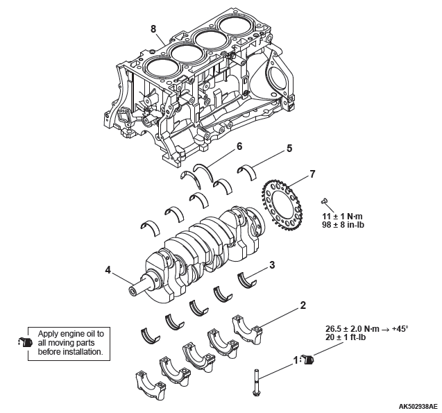
Removal steps
- Crankshaft bearing cap bolt
- Crankshaft bearing cap
- Crankshaft bearing lower
- Crankshaft
- Crankshaft bearing upper
- Thrust bearing
- Crankshaft sensing ring
- Cylinder block
REMOVAL SERVICE POINT
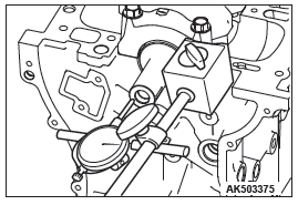
CRANKSHAFT REMOVAL
When temporarily placing the crankshaft with the crankshaft sensing ring attached, temporarily place it on a V-block to prevent teeth of the sensing ring from deforming.
NOTE: If a tooth bends, be sure to replace the crankshaft sensing ring with a new one.
INSTALLATION SERVICE POINTS
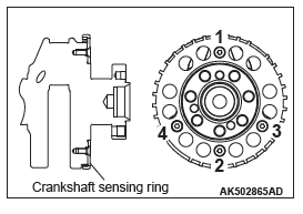
CRANKSHAFT SENSING RING INSTALLATION
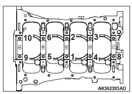
Tighten crankshaft sensing ring bolts to the torque of 11 +- 1 N*m (98 +- 8 in-lb) in the tightening order shown in the illustration.
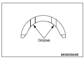
THRUST BEARING INSTALLATION
1. Install the thrust bearing on the Number 3 bearing on the cylinder block side. Application of engine oil makes the installation easy.
2. Install the thrust bearing so that the grooved side is on the crankshaft weight side.
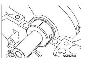
CRANKSHAFT BEARING UPPER INSTALLATION
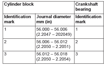
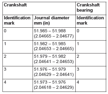
1. When replacing the crankshaft bearing upper, select a bearing with the size corresponding to the crankshaft journal diameter in the table below.
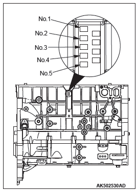
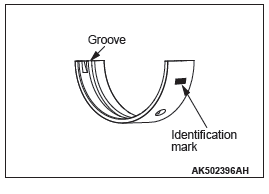
2. The crankshaft bearing upper has an identification mark at the illustrated position.
3. Install the selected crankshaft bearing upper.
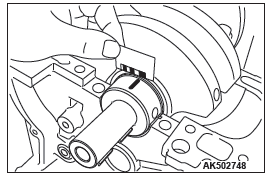
CRANKSHAFT BEARING LOWER INSTALLATION
1. When replacing the crankshaft bearing lower, select a bearing with the size corresponding to the crankshaft journal diameter in the table below.
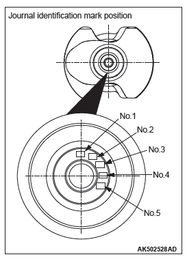
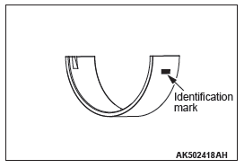
2. The crankshaft bearing lower has an identification mark at the illustrated position.
3. Install the selected crankshaft bearing lower.
CRANKSHAFT BEARING CAP / CRANKSHAFT BEARING CAP BOLT INSTALLATION
1. Install the crankshaft bearing cap with reference to the identification mark as illustrated.
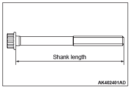
2. Make sure that the underhead length of the bolt is at or below the limit before installing the crankshaft bearing cap bolt. If the length exceeds the limit, replace the bolt with a new one.
Limit: 75.5 − 76.5 mm (2.972 − 3.012 inch)
3. Apply engine oil to the threaded portion and seat surface of the bolt.
4. Tighten crankshaft bearing cap bolts to the torque of 26.5 +- 2.0 N*m (20 +- 1 ft-lb) according to the tightening order.
CAUTION
- When the tightening angle is smaller than the specified tightening angle, the appropriate tightening capacity cannot be secured.
- When the tightening angle is larger than the specified tightening angle, remove the bolt to start from the beginning again according to the procedure.
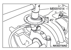
5. Use special tool Angle gauge (MB991614) to tighten bolts 45º according to the tightening order.
6. Check end play of the crankshaft after installing the crankshaft bearing cap. If the end play exceeds the limit, replace the thrust bearing.
Standard value: 0.05 − 0.25 mm (0.002 − 0.010 inch)
Limit: 0.4 mm (0.016 inch)
INSPECTION
CRANKSHAFT OIL CLEARANCE (PLASTIGAGE METHOD)
Oil clearance can be easily measured by using a "plastigage". When using a "plastigage", perform measurement in the following procedure.
1. Fully wipe oil off the outside diameter of the crankshaft and inside diameter of the bearing.
2. Assemble the crankshaft.
3. Place a plastigage in length equal to the bearing width on the journal shaft straight in alignment with the shaft center.
4. Carefully install the bearing cap and tighten the bolt according to the main point of installation >>B<<.
5. Remove the bolt, and then carefully remove the crankshaft bearing cap.
6. Measure the crushed plastigage width (area most widely crushed) using a scale printed on the plastigage bag.
Standard value: 0.012 − 0.030 mm (0.0005 − 0.0012
inch)
Limit: 0.08 mm (0.0031 inch)
CYLINDER BLOCK
1. Visually check the cylinder block for scratch, rust and corrosion. Use a flaw detecting agent to check for cracks. If it is found faulty, repair or replace it.
2. Measure distortion on the top surface of the cylinder block using a straight edge and free gauge.
If distortion exceeds the limit, grind and repair it.
A gasket or the like must not be adhered to the top surface of the cylinder block during measurement.
Distortion on bottom
Limit: Within 0.05 mm (0.0020 inch)
Grinding limit: 0.2 mm (0.008 inch)
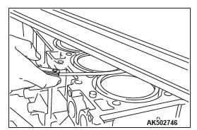
3. Check the cylinder wall for scratch or seizure. If there is any defect, replace the cylinder block.
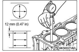
4. Measure the bore and cylindricity of the cylinder using a cylinder gauge.
If the cylinder is excessively worn, repair the cylinder and replace the piston and piston rings.
Measuring points are as shown in the illustration.
Standard value
Cylinder bore: 88 mm (3.46 inch)
Cylindricity: 0.0076 mm (0.0003 inch)
READ NEXT:
 Engine Lubrication
General Information
The lubrication method is a fully force-fed, full-flow filtration
type.
ENGINE OILS
WARNING
Prolonged and repeated contact with mineral
oil will result in the removal of natural f
Engine Cooling
General Information
The cooling system is designed to keep every part of
the engine at appropriate temperature in whatever
condition the engine may be operated. The cooling
method is of the water-cool
Engine Cooling Diagnosis
INTRODUCTION
The system cools the engine so that it does not overheat
and maintains the engine at an optimum temperature.
The system components are the radiator,
water pump, thermostat, condenser fa
SEE MORE:
Multi-information display
The following information is included on the multi-information display: warnings,
odometer/tripmeter, service reminders, engine coolant temperature, fuel remaining,
outside temperature, 4WD operation status, average and momentary fuel consumption,
driving range, average speed and meter illumin
Service precautions
Adequate care of your vehicle at regular intervals serves to preserve the value
and appearance as long as possible.
Maintenance items as described in this owner’s manual can be performed by the
owner.
We recommend you to have the periodic inspection and maintenance performed by
a MITSUBISH
