Mitsubishi Outlander: Engine Cooling Diagnosis
INTRODUCTION
The system cools the engine so that it does not overheat and maintains the engine at an optimum temperature.
The system components are the radiator, water pump, thermostat, condenser fan assembly.
Possible faults include low coolant, contamination, belt loosening and component damage.
TROUBLESHOOTING STRATEGY
Use these steps to plan your diagnostic strategy. If you follow them carefully, you will be sure to find most of the engine cooling faults.
1. Gather information from the customer.
2. Verify that the condition described by the customer exists.
3. Find and repair the malfunction by following the SYMPTOM CHART.
4. Verify that the malfunction is eliminated.
SYMPTOM CHART
SYMPTOM PROCEDURES
Inspection Procedure 1: Coolant Leak
DIAGNOSIS
STEP 1. Check for coolant leaks.
WARNING
When pressure testing the cooling system, slowly release cooling system pressure to avoid getting burned by hot coolant.
CAUTION
- Be sure to completely clean away any moisture from the places checked.
- When the tester is removed, be careful not to spill any coolant.
- When installing and removing the tester and when testing, be careful not to deform the filler neck of the radiator.
Check that the coolant level is up to the filler neck. Install a radiator tester and apply 160 kPa (23 psi) pressure, and then check for leakage from the radiator hose or connections.
Q: Is leakage present from the radiator hose or connections?
YES : Repair or replace the appropriate part, then go to Step 2.
NO : There is no action to be taken.
STEP 2. Retest the system.
Q: It there still coolant leakage?
YES : Return to Step 1.
NO : The procedure is complete.
Inspection Procedure 2: Engine Overheating
DIAGNOSIS
STEP 1. Remove the radiator cap and check for coolant contamination.
Q: Is the coolant contaminated with rust and oil?
YES : Replace it.
NO : There is no action to be taken. Go to Step 2.
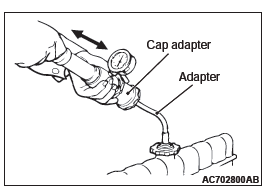
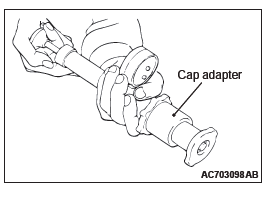
STEP 2. Check the radiator cap valve opening pressure.
NOTE: Be sure that the cap is clean before testing. Rust or other foreign material on the cap seal will cause an improper reading.
- Use a cap adapter to attach the cap to the tester.
- Increase the pressure until the gauge indicator stops moving.
Minimum limit: 83 kPa (12 psi)
Standard value: 93 − 123 kPa (14 − 18 psi)
Q: Does the reading remain at or above the minimum limit?
YES : Go to Step 3.
NO : Replace the radiator cap. Then go to Step 5.
STEP 3. Check thermostat operation.
Q: Does the thermostat operate correctly?
YES : Go to Step 4.
NO : Replace the thermostat, then go to Step 5.
STEP 4. Check the drive belt for slippage or damage.
Refer to Maintenance Service − Drive Belt (For The Generator, Water Pump and Power Steering Pump).
Q: Is the drive belt loose or damaged?
YES : Adjust or replace the drive belt, then go to Step 5.
NO : There is no action to be taken.
STEP 5. Retest the system.
Check the engine coolant temperature.
Q: Is the engine coolant temperature abnormally high?
YES : Return to Step 2.
NO : The procedure is complete.
Inspection Procedure 3: Radiator Fan and Condenser Fan do not Operate <2.4L ENGINE>.
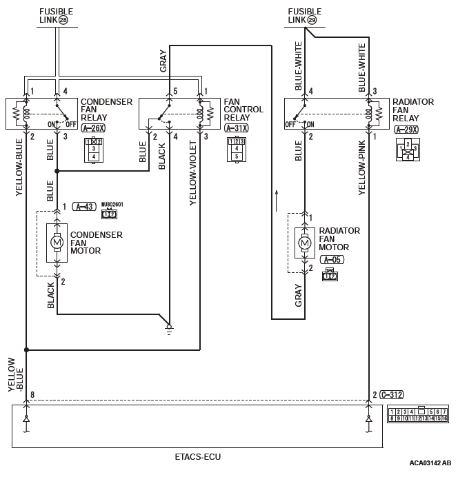
Radiator Fan and Condenser Fan Drive Circuit
CIRCUIT OPERATION
- Based on the signal from the engine coolant temperature sensor and the signal from the secondary pulley speed sensor signal (vehicle speed signal) from the transaxle control module (TCM), and the A/C switch signal from the A/C-ECU, the engine control module (ECM) sends the radiator fan and condenser fan control signal to the ETACS-ECU via CAN bus line.
- Based on the radiator fan and condenser fan control signal from the ECM, the ETACS-ECU turns ON/OFF the radiator fan relay, condenser fan relay, and the fan control relay to control the rotation of the radiator fan motor and condenser fan motor.
TECHNICAL DESCRIPTION
- If the radiator fan and condenser fan do not operate, the radiator fan motor, the condenser fan motor, the radiator fan relay, the condenser fan relay, the fan control relay, the ETACS-ECU may be defective.
- The CAN bus line, ETACS-ECU, CVT system, A/C system, or MFI system may also be defective.
TROUBLESHOOTING HINTS (THE MOST LIKELY CAUSES FOR THIS CASE:)
- Malfunction of CAN bus system.
- Damaged harness or connector.
- Malfunction of the MFI system.
- Malfunction of the CVT system.
- Malfunction of the A/C system.
- Malfunction of fusible link No. 28.
- Malfunction of fusible link No. 29.
- Malfunction of radiator fan relay.
- Malfunction of condenser fan relay.
- Malfunction of fan control relay.
- Malfunction of radiator fan motor.
- Malfunction of condenser fan motor.
- Malfunction of engine compartment relay box.
- Malfunction of ETACS-ECU.
- Malfunction of ECM.
DIAGNOSTIC PROCEDURE
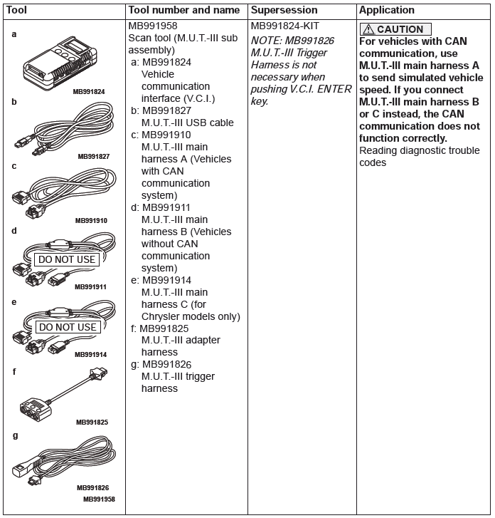
Required Special Tools:
- MB991958: Scan Tool (M.U.T.-III Sub Assembly)
- MB991824: V.C.I.
- MB991827: M.U.T.-III USB Cable
- MB991910: M.U.T.-III Main Harness A
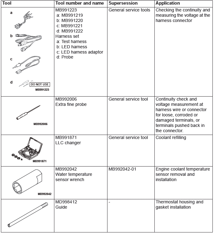
- MB991223: Harness Set
- MB992006: Extra Fine Probe
CAUTION
If there is any problem in the CAN bus lines, an incorrect DTC may be set. Prior to this diagnosis, diagnose the CAN bus lines.
STEP 1. Using scan tool MB991958, check the CAN bus line diagnostics.
Use scan tool to diagnose the CAN bus line.
Q: Is the check result satisfactory?
YES : Go to Step 2.
NO : Repair the CAN bus lines. Then go to Step 23.
STEP 2. Using scan tool MB991958, check the MFI system actuator test.
Using scan tool to check the MFI system actuator test.
- Item 14: Cooling fan
Q: Is the check result normal?
YES : Go to Step 22.
NO : Go to Step 3.
STEP 3. Using scan tool MB991958, read the MFI system DTC.
Using scan tool to read the MFI system DTC.
Q: Is any DTC set?
YES : Repair the MFI system. Then go to Step 23.
NO : Go to Step 4.
STEP 4. Using scan tool MB991958, read the CVT system DTC.
Using scan tool to read the CVT system DTC. YES : Repair the CVT system. Then go to Step 23.
NO : Go to Step 5.
STEP 5. Using scan tool MB991958, read the A/C system DTC.
Using scan tool to read the A/C system DTC.
Q: Is any DTC set?
YES : Repair the A/C system. Then go to Step 23.
NO : Go to Step 6.
STEP 6. Using scan tool MB991958, read the ETACS system DTC.
Using scan tool to read the ETACS system DTC.
Q: Is any DTC set?
YES : Repair the ETACS system.
NO : Go to Step 7.
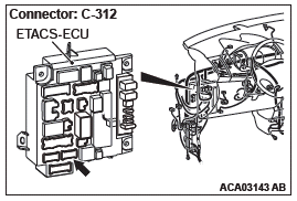
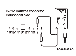
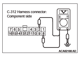
STEP 7. Measure the terminal voltage at ETACS-ECU connector C-312.
- Disconnect the ETACS-ECU connector C-312 and measure at the harness connector side.
- Turn the ignition switch to the "ON" position.
- Measure the terminal voltage between ETACS-ECU connector C-312 terminal number 2 and body ground, and between ETACS-ECU connector C-312 terminal number 8 and body ground.
OK: Battery positive voltage.
Q: Is the measured voltage battery positive voltage?
YES : Go to Step 13.
NO : Go to Step 8.
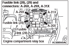
STEP 8. Check the condenser fan relay connector A-26X, radiator fan relay connector A-29X, fan control relay connector A-31X, and ETACS-ECU connector C-312, for loose, corroded or damaged terminals, or terminals pushed back in the connector.
Q: Are the connectors and terminals in good condition?
YES : Go to Step 9.
NO : Repair or replace the damaged connectors or replace the relay box. Then go to Step 23.
STEP 9. Check the harness wire between fusible link number 28 and condenser fan relay connector A-26X terminal number 1, between fusible link number 28 and fan control relay connector A-31X terminal number 1, and between fusible link number 29 and radiator fan relay connector A-29X terminal number 3, for damage.
Check harness wire for open/short circuit and damage.
Q: Are the harness wires in good condition?
YES : Go to Step 10.
NO : Repair or replace the damaged harness wire or replace the relay box. Then go to Step 23.
STEP 10. Check the harness wire between condenser fan relay connector A-26X terminal number 2 and ETACS-ECU connector C-312 terminal number 8, between radiator fan relay connector A-29X terminal number 1 and ETACS-ECU connector C-312 terminal number 2, and between fan control relay connector A-31X terminal number 3 and ETACS-ECU connector C-312 terminal number 8, for damage.
Check harness wire for open/short circuit and damage.
Q: Are the harness wires in good condition?
YES : Go to Step 11.
NO : Repair or replace the damaged harness wire. Then go to Step 23.
STEP 11. Check the radiator fan relay, the condenser fan relay and the fan control relay.
Q: Are the relays in good condition?
YES : Go to Step 12.
NO : Replace the damaged relay. Then go to Step 23.
STEP 12. Check the fusible link number 28 and fusible link number 29.
Q: Are the fusible links in good condition?
YES : Go to Step 20.
NO : Replace the damaged fusible link. Then go to Step 23.
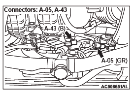
STEP 13. Check the condenser fan relay connector A-26X, radiator fan relay connector A-29X, fan control relay connector A-31X, radiator fan motor connector A-05, and condenser fan motor connector A-43, for loose, corroded or damaged terminals, or terminals pushed back in the connector.
Q: Are the connectors and terminals in good condition?
YES : Go to Step 14.
NO : Repair or replace the damaged connectors or replace the relay box. Then go to Step 23.
STEP 14. Check the harness wire between fusible link number 28 and condenser fan relay connector A-26X terminal number 4, and between fusible link number 29 and radiator fan relay connector A-29X terminal number 4, for damage.
Check harness wire for open/short circuit and damage.
Q: Are the harness wires in good condition?
YES : Go to Step 15.
NO : Repair or replace the damaged harness wire or replace the relay box. Then go to Step 23.
STEP 15. Check the harness wire between condenser fan relay connector A-26X terminal number 3 and condenser fan motor connector A-43 terminal number 1, and between radiator fan relay connector A-29X terminal number 2 and radiator fan motor connector A-05 terminal number 1, for damage.
Check harness wire for open/short circuit and damage.
Q: Are the harness wires in good condition?
YES : Go to Step 16.
NO : Repair or replace the damaged harness wire. Then go to Step 23.
STEP 16. Check the harness wire between radiator fan motor connector A-05 terminal number 2 and fan control relay connector A-31X terminal number 5, and between condenser fan motor connector A-43 terminal number 2 and body ground, for damage.
Check harness wire for open/short circuit and damage.
Q: Are the harness wires in good condition?
YES : Go to Step 17.
NO : Repair or replace the damaged harness wire. Then go to Step 23.
STEP 17. Check the harness wire between fan control relay connector A-31X terminal number 2 and condenser fan motor connector A-43 terminal number 1, and between fan control relay connector A-31X terminal number 4 and body ground, for damage.
Check harness wire for open/short circuit and damage.
Q: Are the harness wires in good condition?
YES : Go to Step 18.
NO : Repair or replace the damaged harness wire. Then go to Step 23.
STEP 18. Check the radiator fan relay, the condenser fan relay and the fan control relay.
Q: Are the relays in good condition?
YES : Go to Step 19.
NO : Replace the damaged relay. Then go to Step 23.
STEP 19. Check the radiator fan motor and the condenser fan motor.
Q: Are the fan motors in good condition?
YES : Go to Step 20.
NO : Replace the damaged fan motor. Then go to Step 23.
STEP 20. Using scan tool MB991958, read the ETACS system DTC.
Using scan tool to read the ETACS system DTC.
Q: Is any DTC set?
YES : Replace the ETACS-ECU. Then go to Step 23.
NO : Go to Step 21.
STEP 21. Using scan tool MB991958, check the MFI system actuator test.
Using scan tool to check the MFI system actuator test.
- Item 14: Cooling fan
Q: Is the check result normal?
YES : Go to Step 22.
NO : Replace the ECM. Then go to Step 23.
STEP 22. Check the symptom.
Q: Does the radiator fan and condenser fan operate normal?
YES : An intermittent malfunction is suspected.
NO : Replace the ECM. Then go to Step 23.
STEP 23. Check the symptom.
Q: Does the radiator fan and condenser fan operate normal?
YES : The procedure is complete.
NO : Return to Step 1.
Inspection Procedure 4: Radiator Fan and Condenser Fan do not Operate <3.0L ENGINE>.
Radiator Fan and Condenser Fan Drive Circuit
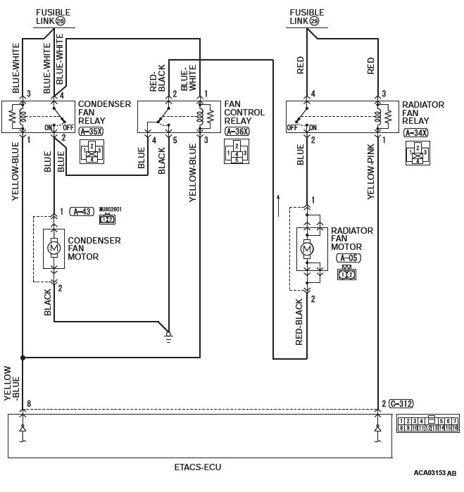
CIRCUIT OPERATION
- Based on the signal from the engine coolant temperature sensor and the output shaft speed sensor signal (vehicle speed signal) from the transaxle control module (TCM), and the A/C switch signal from the A/C-ECU, the engine control module (ECM) sends the radiator fan and condenser fan control signal to the ETACS-ECU via CAN bus line.
- Based on the radiator fan and condenser fan control signal from the ECM, the ETACS-ECU turns ON/OFF the radiator fan relay, condenser fan relay, and the fan control relay to control the rotation of the radiator fan motor and condenser fan motor.
TECHNICAL DESCRIPTION
- If the radiator fan and condenser fan do not operate, the radiator fan motor, the condenser fan motor, the radiator fan relay, the condenser fan relay, the fan control relay, the ETACS-ECU may be defective.
- The CAN bus line, ETACS-ECU, A/T system, A/C system, or MFI system may also be defective.
TROUBLESHOOTING HINTS (THE MOST LIKELY CAUSES FOR THIS CASE:)
- Malfunction of CAN bus system.
- Damaged harness or connector.
- Malfunction of the MFI system.
- Malfunction of the A/T system.
- Malfunction of the A/C system.
- Malfunction of fusible link No. 28.
- Malfunction of fusible link No. 29.
- Malfunction of radiator fan relay.
- Malfunction of condenser fan relay.
- Malfunction of fan control relay.
- Malfunction of radiator fan motor.
- Malfunction of condenser fan motor.
- Malfunction of engine compartment relay box.
- Malfunction of ETACS-ECU.
- Malfunction of engine control module.
DIAGNOSTIC PROCEDURE
Required Special Tools:
- MB991958: Scan Tool (M.U.T.-III Sub Assembly)
- MB991824: V.C.I.
- MB991827: M.U.T.-III USB Cable
- MB991910: M.U.T.-III Main Harness A
- MB991223: Harness Set
- MB992006: Extra Fine Probe
CAUTION
If there is any problem in the CAN bus lines, an incorrect DTC may be set. Prior to this diagnosis, diagnose the CAN bus lines.
STEP 1. Using scan tool MB991958, check the CAN bus line diagnostics.
Use scan tool to diagnose the CAN bus line.
Q: Is the check result satisfactory?
YES : Go to Step 2.
NO : Repair the CAN bus lines. Then go to Step 23.
STEP 2. Using scan tool MB991958, check the MFI system actuator test.
Using scan tool to check the MFI system actuator test.
- Item 14: Cooling fan
Q: Is the check result normal?
YES : Go to Step 22.
NO : Go to Step 3.
STEP 3. Using scan tool MB991958, read the MFI system DTC.
Using scan tool to read the MFI system DTC.
Q: Is any DTC set?
YES : Repair the MFI system. Then go to Step 23.
NO : Go to Step 4.
STEP 4. Using scan tool MB991958, read the A/T system DTC.
Using scan tool to read the A/T system DTC.
Q: Is any DTC set?
YES : Repair the A/T system. Then go to Step 23.
NO : Go to Step 5.
STEP 5. Using scan tool MB991958, read the A/C system DTC.
Using scan tool to read the A/C system DTC.
Q: Is any DTC set?
YES : Repair the A/C system. Then go to Step 23.
NO : Go to Step 6.
STEP 6. Using scan tool MB991958, read the ETACS system DTC.
Using scan tool to read the ETACS system DTC.
Q: Is any DTC set?
YES : Repair the ETACS system. Then go to Step 23.
NO : Go to Step 7.
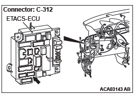
STEP 7. Measure the terminal voltage at ETACS-ECU connector C-312.
- Disconnect the ETACS-ECU connector C-312 and measure at the harness connector side.
- Turn the ignition switch to the "ON" position.
- Measure the terminal voltage between ETACS-ECU connector C-312 terminal number 2 and body ground, and between ETACS-ECU connector C-312 terminal number 8 and body ground.
OK: Battery positive voltage.
Q: Is the measured voltage battery positive voltage?
YES : Go to Step 13.
NO : Go to Step 8.
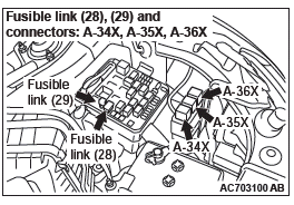
STEP 8. Check the radiator fan relay connector A-34X, condenser fan relay connector A-35X, fan control relay connector A-36X, and ETACS-ECU connector C-312, for loose, corroded or damaged terminals, or terminals pushed back in the connector.
Q: Are the connectors and terminals in good condition?
YES : Go to Step 9.
NO : Repair or replace the damaged connectors or replace the relay box. Then go to Step 23.
STEP 9. Check the harness wire between fusible link number 28 and condenser fan relay connector A-35X terminal number 3, between fusible link number 28 and condenser fan relay connector A-35X terminal number 4, between condenser fan relay connector A-35X terminal number 4 and fan control relay connector A-36X terminal number 1, and between fusible link number 29 and radiator fan relay connector A-34X terminal number 3, for damage.
Check harness wire for open/short circuit and damage.
Q: Are the harness wires in good condition?
YES : Go to Step 10.
NO : Repair or replace the damaged harness wire. Then go to Step 23.
STEP 10. Check the harness wire between radiator fan relay connector A-34X terminal number 1 and ETACS-ECU connector C-312 terminal number 2, between condenser fan relay connector A-35X terminal number 1 and ETACS-ECU connector C-312 terminal number 8, and between fan control relay connector A-36X terminal number 3 and ETACS-ECU connector C-312 terminal number 8, for damage.
Check harness wire for open/short circuit and damage.
Q: Are the harness wires in good condition?
YES : Go to Step 11.
NO : Repair or replace the damaged harness wire. Then go to Step 23.
STEP 11. Check the radiator fan relay, the condenser fan relay and the fan control relay.
Q: Are the relays in good condition?
YES : Go to Step 12.
NO : Replace the damaged relay. Then go to Step 23.
STEP 12. Check the fusible link number 28 and fusible link number 29.
Q: Are the fusible links in good condition?
YES : Go to Step 20.
NO : Replace the damaged fusible link. Then go to Step 23.
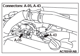
STEP 13. Check the radiator fan relay connector A-34X, condenser fan relay connector A-35X, fan control relay connector A-36X, radiator fan motor connector A-05, and condenser fan motor connector A-43, for loose, corroded or damaged terminals, or terminals pushed back in the connector.
Q: Are the connectors and terminals in good condition?
YES : Go to Step 14.
NO : Repair or replace the damaged connectors or replace the relay box. Then go to Step 23.
STEP 14. Check the harness wire between fusible link number 28 and condenser fan relay connector A-35X terminal number 4, and between fusible link number 29 and radiator fan relay connector A-34X terminal number 4, for damage.
Check harness wire for open/short circuit and damage.
Q: Are the harness wires in good condition?
YES : Go to Step 15.
NO : Repair or replace the damaged harness wire. Then go to Step 23.
STEP 15. Check the harness wire between radiator fan relay connector A-34X terminal number 2 and radiator fan motor connector A-05 terminal number 1, and between condenser fan relay connector A-35X terminal number 2 and condenser fan motor connector A-43 terminal number 1, for damage.
Check harness wire for open/short circuit and damage.
Q: Are the harness wires in good condition?
YES : Go to Step 16.
NO : Repair or replace the damaged harness wire. Then go to Step 23.
STEP 16. Check the harness wire between radiator fan motor connector A-05 terminal number 2 and fan control relay connector A-36X terminal number 2, and between condenser fan motor connector A-43 terminal number 2 and body ground, for damage.
Check harness wire for open/short circuit and damage.
Q: Is the check result normal?
YES : Go to Step 17.
NO : Repair or replace the damaged harness wire. Then go to Step 23.
STEP 17. Check the harness wire between fan control relay connector A-36X terminal number 4 and condenser fan relay connector A-35X terminal number 2, and between fan control relay connector A-36X terminal number 5 and body ground, for damage.
Check harness wire for open/short circuit and damage.
Q: Are the harness wires in good condition?
YES : Go to Step 18.
NO : Repair or replace the damaged harness wire. Then go to Step 23.
STEP 18. Check the radiator fan relay, the condenser fan relay and the fan control relay.
Q: Are the relays in good condition?
YES : Go to Step 19.
NO : Replace the damaged relay. Then go to Step 23.
STEP 19. Check the radiator fan motor and the condenser fan motor.
Q: Are the fan motors in good condition?
YES : Go to Step 20.
NO : Replace the damaged fan motor.
Then go to Step 23.
STEP 20. Using scan tool MB991958, read the ETACS system DTC.
Using scan tool to read the ETACS system DTC.
Q: Is any DTC set?
YES : Replace the ETACS-ECU. Then go to Step 23.
NO : Go to Step 21.
STEP 21. Using scan tool MB991958, check the MFI system actuator test.
Using scan tool to check the MFI system actuator test.
- Item 14: Cooling fan
Q: Is the check result normal?
YES : Go to Step 22.
NO : Replace the ECM. Then go to Step 23.
STEP 22. Check the symptom.
Q: Does the radiator fan and condenser fan operate normal?
YES : An intermittent malfunction is suspected.
NO : Replace the ECM. Then go to Step 23.
STEP 23. Check the symptom.
Q: Does the radiator fan and condenser fan operate normal?
YES : The procedure is complete.
NO : Return to Step 1.
Special Tools
READ NEXT:
 On-vehicle Service
ENGINE COOLANT LEAK CHECK
WARNING
When pressure testing the cooling system, slowly
release cooling system pressure to avoid getting
burned by hot coolant.
CAUTION
Be sure to completely clean away a
Thermostat
REMOVAL AND INSTALLATION <2.4L ENGINE>
Pre-removal Operation
Engine Coolant Draining
Engine Upper Cover Removal
Air Cleaner Assembly Removal
Post-installation Operation
Air Cleaner Asse
Water Hose and Water Pipe
REMOVAL AND INSTALLATION <2.4L ENGINE>
Pre-removal Operation
Engine Coolant Draining
Engine Upper Cover Removal
Air Cleaner Assembly Removal
Thermostat Removal
Post-installation Operatio
SEE MORE:
To use the external audio input function(vehicles with a rear-seat display)
Auxiliary Video connecter (RCA).
A- Left audio input connecter (white).
B- Right audio input connecter (red).
C- Video input connecter (yellow).
You can listen to commercially available audio equipment, such as a portable
audio system, from your vehicle’s speakers, by connecting the audio
Engine Control
GENERAL INFORMATION
For the accelerator system, the electronic throttle
valve control system, disposing of the accelerator
cable, is adopted.
This system determines the amount of pressure
applied to the accelerator pedal using the built-in
accelerator pedal position sensor of the accelerator
pedal
