Mitsubishi Outlander: DTC U0020, U0021, U0022, U0023, U0024, U0025, U0026, U0141, U0151, U0155, U0164, U0168, U0184, U0195, U0245, U1419, U141A, U141B, U141C, U1423
DTC U0020: CAN-B Bus Off Performance
DTC U0021: CAN-B Bus(H1) Circuit Open
DTC U0022: CAN-B Bus(H1) Shorted to Circuit Ground
DTC U0023: CAN-B Bus(H1) Shorted to Circuit Power Supply
DTC U0024: CAN-B Bus(L0) Circuit Open
DTC U0025: CAN-B Bus(L0) Shorted to Circuit Ground
DTC U0026: CAN-B Bus(L0) Shorted to Circuit Power Supply
CAUTION
- If the DTC U0020, U0021, U0022, U0023, U0024, U0025, U0026 is set in the occupant classification-ECU, always diagnose the CAN main bus lines.
- When replacing the ECU, always check that the communication circuit is normal.
DTC SET CONDITIONS
If the CAN-B circuit malfunction is present, the occupant classification-ECU sets the DTC U0020, U0021, U0022, U0023, U0024, U0025, U0026.
JUDGMENT CRITERIA
Because of the CAN-B bus circuit malfunction, if occupant classification-ECU becomes unable to perform the normal data transmission, occupant classification- ECU determines that an abnormality is present.
TROUBLESHOOTING HINTS
The CAN bus line may be defective
DIAGNOSIS
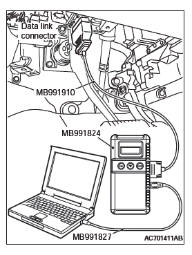
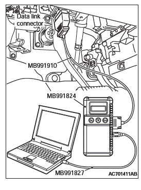
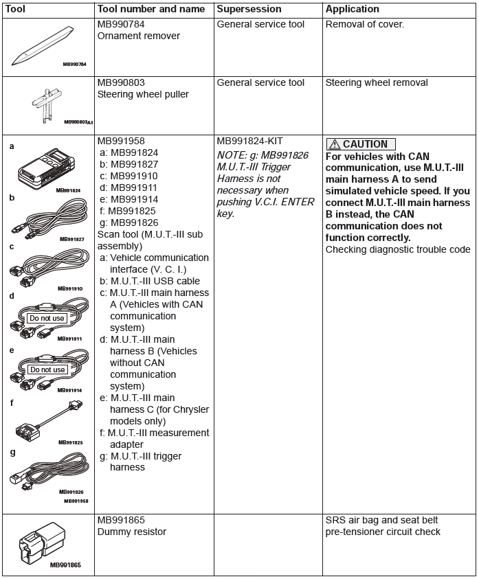
Required Special Tools:
- MB991958: Scan Tool (M.U.T.-III Sub Assembly)
- MB991824: Vehicles Communication Interface (V.C.I.)
- MB991827: M.U.T.-III USB Cable
- MB991910: M.U.T.-III Main Harness A (Vehicles with CAN communication system)
STEP 1. Using scan tool MB991958, diagnose the CAN bus line.
- Turn the ignition switch to the "ON" position.
- Diagnose the CAN bus line.
- Turn the ignition switch to the "LOCK" (OFF) position.
Q: Is the CAN bus line found to be normal?
YES : Go to Step 2.
NO : Repair the CAN bus line.
STEP 2. Recheck for diagnostic trouble code.
Check again if the DTC is set to the occupant classification- ECU.
CAUTION To prevent damage to scan tool MB991958, always turn the ignition switch to the "LOCK" (OFF) position before connecting or disconnecting scan tool MB991958.
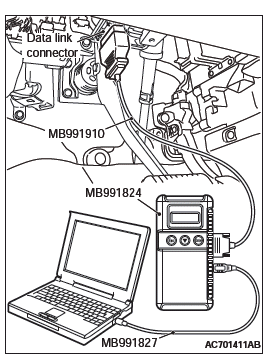
- Connect scan tool MB991958. Refer to "How to connect the scan tool".
- Turn the ignition switch to the "ON" position.
- Check if DTC is set.
- Turn the ignition switch to the "LOCK" (OFF) position.
Q: Is the DTC set?
YES : Replace the passenger seat cushion frame assembly.
NO : There is an intermittent malfunction such as poor engaged connector(s) or open circuit.
DTC U0141: ETACS CAN Timeout
CAUTION
- If the DTC U0141 is set in the occupant classification- ECU, always diagnose the CAN main bus lines.
- When replacing the ECU, always check that the communication circuit is normal.
DIAGNOSTIC FUNCTION
If the signal from ETACS-ECU cannot be received, the occupant classification-ECU sets the DTC U0141.
JUDGMENT CRITERIA
Because of the CAN-B bus circuit malfunction, if occupant classification-ECU becomes unable to perform the normal data transmission, occupant classification- ECU determines that an abnormality is present.
TROUBLESHOOTING HINTS
- The CAN bus line may be defective
- The ETACS-ECU may be defective
- The occupant classification-ECU may be defective
DIAGNOSIS
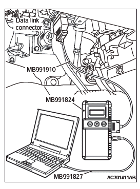
Required Special Tools:
- MB991958: Scan Tool (M.U.T.-III Sub Assembly)
- MB991824: Vehicles Communication Interface (V.C.I.)
- MB991827: M.U.T.-III USB Cable
- MB991910: M.U.T.-III Main Harness A (Vehicles with CAN communication system)
STEP 1. Using scan tool MB991958, diagnose the CAN bus line.
CAUTION To prevent damage to scan tool MB991958, always turn the ignition switch to the "LOCK" (OFF) position before connecting or disconnecting scan tool MB991958.
- Connect scan tool MB991958. Refer to "How to connect the scan tool".
- Turn the ignition switch to the "ON" position.
- Diagnose the CAN bus line.
- Turn the ignition switch to the "LOCK" (OFF) position.
Q: Is the CAN bus line found to be normal?
YES : Go to Step 2.
NO : Repair the CAN bus line.
STEP 2. Using scan tool MB991958, read the ETACS-ECU diagnostic trouble code.
Check again if the DTC is set to the ETACS-ECU.
Q: Is the DTC set?
YES : Diagnose the ETACS-ECU. Then go to Step 4.
NO : Go to Step 3.
STEP 3. Using scan tool MB991958, read diagnostic trouble code No. U0141 for other system.
Check if the DTC U0141 is set in SRS-ECU, combination meter, A/C-ECU, KOS-ECU or WCM, hands free module, CAN box unit, radio and CD player, satellite radio tuner.
Q: Is the DTC set?
YES : Replace the ETACS-ECU.
NO : Go to Step 4.
STEP 4. Recheck for diagnostic trouble code.
Check again if the DTC is set to the occupant classification- ECU.
- Erase the DTC.
- Turn the ignition switch from "LOCK" (OFF) position to "ON" position.
- Check if DTC is set.
- Turn the ignition switch to the "LOCK" (OFF) position.
Q: Is the DTC set?
YES : Replace the passenger seat cushion frame assembly (Refer to GROUP 52A, Front Seat Assembly).
NO : There is an intermittent malfunction such as poor engaged connector(s) or open circuit (Refer to GROUP 00, How to Cope with Intermittent Malfunction).
DTC U0151: SRS-ECU CAN timeout
CAUTION
- If DTC U0151 is set in the occupant classification- ECU, always diagnose the CAN main bus lines.
- When replacing the ECU, always check that the communication circuit is normal.
DIAGNOSTIC FUNCTION
If the signal from SRS-ECU cannot be received, the occupant classification system sets DTC U0151.
JUDGMENT CRITERIA
Because of the CAN-B bus circuit malfunction, if occupant classification-ECU becomes unable to perform the normal data transmission, occupant classification- ECU determines that an abnormality is present.
TROUBLESHOOTING HINTS
- The CAN bus line may be defective
- The SRS-ECU may be defective
- The occupant classification-ECU may be defective
DIAGNOSIS
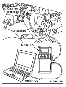
Required Special Tools:
- MB991958: Scan Tool (M.U.T.-III Sub Assembly)
- MB991824: Vehicles Communication Interface (V.C.I.)
- MB991827: M.U.T.-III USB Cable
- MB991910: M.U.T.-III Main Harness A (Vehicles with CAN communication system)
STEP 1. Using scan tool MB991958, diagnose the CAN bus line.
CAUTION To prevent damage to scan tool MB991958, always turn the ignition switch to the "LOCK" (OFF) position before connecting or disconnecting scan tool MB991958.
- Connect scan tool MB991958. Refer to "How to connect the Scan Tool (M.U.T.-III)".
- Turn the ignition switch to the "ON" position.
- Diagnose the CAN bus line.
- Turn the ignition switch to the "LOCK" (OFF) position.
Q: Is the CAN bus line found to be normal?
YES : Go to Step 2.
NO : Repair the CAN bus line.
STEP 2. Using scan tool MB991958, read the SRS-ECU diagnostic trouble code.
Check again if the DTC is set to the SRS-ECU.
Q: Is the DTC set?
YES : Diagnose the SRS-ECU. Then go to Step 4.
NO : Go to Step 3.
STEP 3. Using scan tool MB991958, read diagnostic trouble code No. U0151 for other system.
Check if the DTC U0151 is set in ETACS-ECU, combination meter, A/C-ECU, KOS-ECU or WCM, hands free module, CAN box unit, radio and CD player, satellite radio tuner.
Q: Is the DTC set?
YES : Replace the SRS-ECU.
NO : Go to Step 4.
STEP 4. Recheck for diagnostic trouble code.
Check again if the DTC is set to the occupant classification- ECU.
- Erase the DTC.
- Turn the ignition switch from "LOCK" (OFF) position to "ON" position.
- Check if DTC is set.
- Turn the ignition switch to the "LOCK" (OFF) position.
Q: Is the DTC set?
YES : Replace the passenger seat cushion frame assembly.
NO : There is an intermittent malfunction such as poor engaged connector(s) or open circuit (Refer to GROUP 00, How to Cope with Intermittent Malfunction).
DTC U0155: Combination Meter CAN Timeout
CAUTION
- If the DTC U0155 is set in the occupant classification- ECU, always diagnose the CAN main bus lines.
- When replacing the ECU, always check that the communication circuit is normal.
TROUBLE JUDGMENT
If the signal from combination meter cannot be received, the occupant classification-ECU sets the DTC U0155.
JUDGMENT CRITERIA
Because of the CAN-B bus circuit malfunction, if occupant classification-ECU becomes unable to perform the normal data transmission, occupant classification- ECU determines that an abnormality is present.
TROUBLESHOOTING HINTS
- The CAN bus line may be defective
- The combination meter may be defective
- The occupant classification-ECU may be defective
DIAGNOSIS
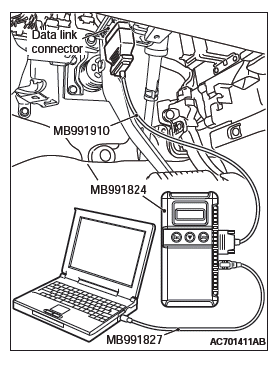
Required Special Tools:
- MB991958: Scan Tool (M.U.T.-III Sub Assembly)
- MB991824: Vehicles Communication Interface (V.C.I.)
- MB991827: M.U.T.-III USB Cable
- MB991910: M.U.T.-III Main Harness A (Vehicles with CAN communication system)
STEP 1. Using scan tool MB991958, diagnose the CAN bus line.
CAUTION To prevent damage to scan tool MB991958, always turn the ignition switch to the "LOCK" (OFF) position before connecting or disconnecting scan tool MB991958.
- Connect scan tool MB991958. Refer to "How to connect the scan tool".
- Turn the ignition switch to the "ON" position.
- Diagnose the CAN bus line.
- Turn the ignition switch to the "LOCK" (OFF) position.
Q: Is the CAN bus line found to be normal?
YES : Go to Step 2.
NO : Repair the CAN bus line.
STEP 2. Using scan tool MB991958, read the combination meter diagnostic trouble code.
Check if DTC is set to the combination meter.
Q: Is the DTC set?
YES : Diagnose the combination meter. Then go to Step 4.
NO : Go to Step 3.
STEP 3. Using scan tool MB991958, read diagnostic trouble code No. U0155 for other system.
Check if the DTC U0155 is set in ETACS-ECU, SRS-ECU, A/C-ECU, KOS-ECU or WCM, hands free module, CAN box unit, radio and CD player, satellite radio tuner.
Q: Is the DTC set?
YES : Replace the combination meter.
NO : Go to Step 4.
STEP 4. Recheck for diagnostic trouble code.
Check again if the DTC is set to the occupant classification- ECU.
- Erase the DTC.
- Turn the ignition switch from "LOCK" (OFF) position to "ON" position.
- Check if DTC is set.
- Turn the ignition switch to the "LOCK" (OFF) position.
Q: Is the DTC set?
YES : Replace the passenger seat cushion frame assembly.
NO : There is an intermittent malfunction such as poor engaged connector(s) or open circuit (Refer to GROUP 00, How to Cope with Intermittent Malfunction).
DTC U0164: A/C-ECU CAN Timeout
CAUTION
- If the DTC U0164 is set in the occupant classification- ECU, always diagnose the CAN main bus lines.
- When replacing the ECU, always check that the communication circuit is normal.
DIAGNOSTIC FUNCTION
If the signal from A/C-ECU cannot be received, the occupant classification-ECU sets the DTC U0164.
JUDGMENT CRITERIA
Because of the CAN-B bus circuit malfunction, if the occupant classification-ECU becomes unable to perform the normal data transmission, the occupant classification-ECU determines that an abnormality is present.
TROUBLESHOOTING HINTS
- The CAN bus line may be defective
- The A/C-ECU may be defective
- The occupant classification-ECU may be defective
DIAGNOSIS
Required Special Tools:
- MB991958: Scan Tool (M.U.T.-III Sub Assembly)
- MB991824: Vehicles Communication Interface (V.C.I.)
- MB991827: M.U.T.-III USB Cable
- MB991910: M.U.T.-III Main Harness A (Vehicles with CAN communication system)
STEP 1. Using scan tool MB991958, diagnose the CAN bus line.
CAUTION To prevent damage to scan tool MB991958, always turn the ignition switch to the "LOCK" (OFF) position before connecting or disconnecting scan tool MB991958.
- Connect scan tool MB991958. Refer to "How to connect the Scan Tool (M.U.T.-III)".
- Turn the ignition switch to the "ON" position.
- Diagnose the CAN bus line.
- Turn the ignition switch to the "LOCK" (OFF) position.
Q: Is the CAN bus line found to be normal?
YES : Go to Step 2.
NO : Repair the CAN bus line.
STEP 2. Using scan tool MB991958, read the A/C diagnostic trouble code.
Check if DTC is set to the A/C-ECU.
Q: Is the DTC set?
YES : Diagnose the A/C. Then go to Step 4.
NO : Go to Step 3.
STEP 3. Using scan tool MB991958, read diagnostic trouble code No. U0164 for other system.
Check if the DTC U0164 is set in ETACS-ECU, SRS-ECU, combination meter, KOS-ECU or WCM, hands free module, CAN box unit, radio and CD player, satellite radio tuner.
Q: Is the DTC set?
YES : Replace the A/C-ECU.
NO : Go to Step 4.
STEP 4. Recheck for diagnostic trouble code.
Check again if the DTC is set to the occupant classification- ECU.
- Erase the DTC.
- Turn the ignition switch from "LOCK" (OFF) position to "ON" position.
- Check if DTC is set.
- Turn the ignition switch to the "LOCK" (OFF) position.
Q: Is the DTC set?
YES : Replace the passenger seat cushion frame assembly.
NO : There is an intermittent malfunction such as poor engaged connector(s) or open circuit (Refer to GROUP 00, How to Cope with Intermittent Malfunction).
DTC U0168: KOS-ECU or WCM CAN Timeout
CAUTION
- If DTC U0168 is set in the occupant classification- ECU, always diagnose the CAN main bus lines.
- When replacing the ECU, always check that the communication circuit is normal.
DIAGNOSTIC FUNCTION
If the signal from KOS-ECU or WCM cannot be received, the occupant classification-ECU sets the DTC U0168.
JUDGMENT CRITERIA
Because of the CAN-B bus circuit malfunction, if the occupant classification-ECU becomes unable to perform the normal data transmission, the occupant classification-ECU determines that an abnormality is present.
TROUBLESHOOTING HINTS
- Malfunction of CAN bus line may be defective.
- Malfunction of the KOS-ECU may be defective.
- Malfunction of the WCM may be defective.
- Malfunction of the occupant classification-ECU may be defective.
DIAGNOSIS
Required Special Tools:
- MB991958: Scan Tool (M.U.T.-III Sub Assembly)
- MB991824: Vehicles Communication Interface (V.C.I.)
- MB991827: M.U.T.-III USB Cable
- MB991910: M.U.T.-III Main Harness A (Vehicles with CAN communication system)
STEP 1. Using scan tool MB991958, diagnose the CAN bus line.
CAUTION To prevent damage to scan tool MB991958, always turn the ignition switch to the "LOCK" (OFF) position before connecting or disconnecting scan tool MB991958.
- Connect scan tool MB991958. Refer to "How to connect the Scan Tool (M.U.T.-III)".
- Turn the ignition switch to the "ON" position.
- Diagnose the CAN bus line.
- Turn the ignition switch to the "LOCK" (OFF) position.
Q: Is the CAN bus line found to be normal?
YES : Go to Step 2.
NO : Repair the CAN bus line.
STEP 2. Using scan tool MB991958, read the KOS-ECU or WCM diagnostic trouble code.
Check again if the DTC is set to the KOS-ECU or WCM.
Q: Is the DTC set?
YES : Diagnose the KOS or WCM. Then go to Step 4.
NO : Go to Step 3.
STEP 3. Using scan tool MB991958, read diagnostic trouble code No. U0168 for other system.
Check if the DTC U0168 is set in ETACS-ECU, SRS-ECU, combination meter, A/C-ECU, hands free module, CAN box unit, radio and CD player, satellite radio tuner.
Q: Is the DTC set?
YES : Replace the KOS -ECU or WCM.
NO : Go to Step 4.
STEP 4. Recheck for diagnostic trouble code.
Check again if the DTC is set to the occupant classification- ECU.
- Erase the DTC.
- Turn the ignition switch from "LOCK" (OFF) position to "ON" position.
- Check if DTC is set.
- Turn the ignition switch to the "LOCK" (OFF) position.
Q: Is the DTC set?
YES : Replace the passenger seat cushion frame assembly.
NO : There is an intermittent malfunction such as poor engaged connector(s) or open circuit.
DTC U0184: Audio CAN Timeout
CAUTION
- If the DTC U0184 is set in the occupant classification- ECU, always diagnose the CAN main bus lines.
- When replacing the ECU, always check that the communication circuit is normal.
DIAGNOSTIC FUNCTION
When the signals from radio and CD player or CD changer cannot be received, the occupant classification- ECU sets the DTC U0184.
JUDGMENT CRITERIA
Because of the CAN-B bus circuit malfunction, if occupant classification-ECU becomes unable to perform the normal data transmission, occupant classification- ECU determines that an abnormality is present.
TROUBLESHOOTING HINTS
- The CAN bus line may be defective
- The radio and CD player or CD changer may be defective
- The occupant classification-ECU may be defective
DIAGNOSIS
Required Special Tools:
- MB991958: Scan Tool (M.U.T.-III Sub Assembly)
- MB991824: Vehicles Communication Interface (V.C.I.)
- MB991827: M.U.T.-III USB Cable
- MB991910: M.U.T.-III Main Harness A (Vehicles with CAN communication system)
STEP 1. Using scan tool MB991958, diagnose the CAN bus line.
CAUTION To prevent damage to scan tool MB991958, always turn the ignition switch to the "LOCK" (OFF) position before connecting or disconnecting scan tool MB991958.
- Connect scan tool MB991958. Refer to "How to connect the scan tool".
- Turn the ignition switch to the "ON" position.
- Diagnose the CAN bus line.
- Turn the ignition switch to the "LOCK" (OFF) position.
Q: Is the CAN bus line found to be normal?
YES : Go to Step 2.
NO : Repair the CAN bus line.
STEP 2. Using scan tool MB991958, read the audio diagnostic trouble code.
Check if the DTC is set to the audio.
Q: Is the DTC set?
YES : Diagnose the radio and CD player. Then go to Step 4.
NO : Go to Step 3.
STEP 3. Using scan tool MB991958, read diagnostic trouble code No. U0184 for other system.
Check if the DTC U0184 is set in ETACS-ECU, SRS-ECU, combination meter, A/C-ECU, KOS-ECU or WCM, hands free module, satellite radio tuner.
Q: Is the DTC set?
YES : Replace the radio and CD player.
NO : Go to Step 4.
STEP 4. Recheck for diagnostic trouble code.
Check again if the DTC is set to the occupant classification- ECU.
- Erase the DTC.
- Turn the ignition switch from "LOCK" (OFF) position to "ON" position.
- Check if DTC is set.
- Turn the ignition switch to the "LOCK" (OFF) position.
Q: Is the DTC set?
YES : Replace the passenger seat cushion frame assembly.
NO : There is an intermittent malfunction such as poor engaged connector(s) or open circuit.
DTC U0195: Satellite Radio Tuner CAN Timeout
CAUTION
- If the DTC U0195 is set in the occupant classification- ECU, always diagnose the CAN main bus lines.
- When replacing the ECU, always check that the communication circuit is normal.
TROUBLE JUDGMENT
If the signal from satellite radio tuner cannot be received, the occupant classification-ECU sets the DTC U0195.
JUDGMENT CRITERIA
Because of the CAN-B bus circuit malfunction, if occupant classification-ECU becomes unable to perform the normal data transmission, occupant classification- ECU determines that an abnormality is present.
TROUBLESHOOTING HINTS
- The CAN bus may be defective.
- The satellite radio tuner may be defective.
- The occupant classification-ECU may be defective.
DIAGNOSIS
Required Special Tools:
- MB991958: Scan Tool (M.U.T.-III Sub Assembly)
- MB991824: Vehicles Communication Interface (V.C.I.)
- MB991827: M.U.T.-III USB Cable
- MB991910: M.U.T.-III Main Harness A (Vehicles with CAN communication system)
STEP 1. Using scan tool MB991958, diagnose the CAN bus line.
CAUTION To prevent damage to scan tool MB991958, always turn the ignition switch to the "LOCK" (OFF) position before connecting or disconnecting scan tool MB991958.
- Connect scan tool MB991958. Refer to "How to connect the scan tool".
- Turn the ignition switch to the "ON" position.
- Diagnose the CAN bus line.
- Turn the ignition switch to the "LOCK" (OFF) position.
Q: Is the CAN bus line found to be normal?
YES : Go to Step 2.
NO : Repair the CAN bus line.
STEP 2. Using scan tool MB991958, read the satellite radio tuner diagnostic trouble code.
Check if DTC is set to the satellite radio tuner.
Q: Is the DTC set?
YES : Diagnose the satellite radio tuner. Then go to Step 4.
NO : Go to Step 3.
STEP 3. Using scan tool MB991958, read diagnostic trouble code No. U0195 for other system.
Check if the DTC U0195 is set in ETACS-ECU, SRS-ECU, A/C-ECU, hands free module, CAN box unit, radio and CD player, WCM.
Q: Is the DTC set?
YES : Replace the satellite radio tuner.
NO : Go to Step 4.
STEP 4. Recheck for diagnostic trouble code.
Check again if the DTC is set to the occupant classification- ECU.
- Erase the DTC.
- Turn the ignition switch from "LOCK" (OFF) position to "ON" position.
- Check if DTC is set.
- Turn the ignition switch to the "LOCK" (OFF) position.
Q: Is the DTC set?
YES : Replace the passenger seat cushion frame assembly.
NO : There is an intermittent malfunction such as poor engaged connector(s) or open circuit (Refer to GROUP 00, How to Cope with Intermittent Malfunction).
DTC U0245: CAN box unit CAN timeout
CAUTION
- If DTC U0245 is set in the occupant classification- ECU, always diagnose the CAN main bus lines.
- When replacing the ECU, always check that the communication circuit is normal.
DIAGNOSTIC FUNCTION
When the signals from audio visual navigation unit cannot be received, the occupant classification system sets DTC U0245.
JUDGMENT CRITERIA
Because of the CAN-B bus circuit malfunction, if audio visual navigation becomes unable to perform the normal data transmission, occupant classification- ECU determines that an abnormality is present.
TROUBLESHOOTING HINTS
- The CAN bus line may be defective.
- The occupant classification-ECU may be defective.
- The audio visual navigation unit may be defective.
DIAGNOSIS
Required Special Tools:
- MB991958: Scan Tool (M.U.T.-III Sub Assembly)
- MB991824: Vehicles Communication Interface (V.C.I.)
- MB991827: M.U.T.-III USB Cable
- MB991910: M.U.T.-III Main Harness A (Vehicles with CAN communication system)
STEP 1. Using scan tool MB991958, diagnose the CAN bus line.
CAUTION To prevent damage to scan tool MB991958, always turn the ignition switch to the "LOCK" (OFF) position before connecting or disconnecting scan tool MB991958.
- Connect scan tool MB991958. Refer to "How to connect the Scan Tool (M.U.T.-III)".
- Turn the ignition switch to the "ON" position.
- Diagnose the CAN bus line.
- Turn the ignition switch to the "LOCK" (OFF) position.
Q: Is the CAN bus line found to be normal?
YES : Go to Step 2.
NO : Repair the CAN bus line.
STEP 2. Using scan tool MB991958, read the audio visual navigation unit diagnostic trouble code.
Check if DTC is set to the audio visual navigation unit.
Q: Is the DTC set?
YES : Diagnose the MMCS. Then go to Step 4.
NO : Go to Step 3.
STEP 3. Using scan tool MB991958, read diagnostic trouble code No. U0245 for other system.
Check if the DTC U0245 is set in ETACS-ECU, combination meter, KOS-ECU or WCM, hands free module.
Q: Is the DTC set?
YES : Replace the CAN box unit (Refer to GROUP 54A, MMCSP).
NO : Go to Step 4.
STEP 4. Recheck for diagnostic trouble code.
Check again if the DTC is set to the occupant classification- ECU.
- Erase the DTC.
- Turn the ignition switch from "LOCK" (OFF) position to "ON" position.
- Check if DTC is set.
- Turn the ignition switch to the "LOCK" (OFF) position.
Q: Is the DTC set?
YES : Replace the passenger seat cushion frame assembly (Refer to GROUP 52A, Front Seat Assembly).
NO : There is an intermittent malfunction such as poor engaged connector(s) or open circuit (Refer to GROUP 00, How to Cope with Intermittent Malfunction).
DTC U1419: The signal from a weight sensor (front: LH) is unusual
DTC U141A: The signal from a weight sensor (front: RH) is unusual
DTC U141B: The signal from a weight sensor (rear: LH) is unusual
DTC U141C: The signal from a weight sensor (rear: RH) is unusual
DTC U1423: The signal from a weight sensor is unusual
DTC SET CONDITIONS
There DTCs are set if communication between the weight sensor and the occupant classification-ECU is not possible or faulty.
TROUBLESHOOTING HINTS
- Malfunction of weight sensor
- The occupant classification-ECU may be defective
DIAGNOSIS
Required Special Tools:
- MB991958: Scan Tool (M.U.T.-III Sub Assembly)
- MB991824: Vehicle Communication Interface (V.C.I.)
- MB991827: M.U.T.-III USB Cable
- MB991910: M.U.T.-III Main Harness A (Vehicles with CAN communication system)
STEP 1. Recheck for diagnostic trouble code.
Check again if the DTC is set.
- Erase the DTC.
- Turn the ignition switch to the "ON" position.
- Check if the DTC is set.
- Turn the ignition switch to the "LOCK" (OFF) position.
Q: Is the DTC set?
YES : Go to Step 2.
NO : There is an intermittent malfunction such as poor engaged connector(s) or open circuit (Refer to GROUP 00, How to Cope with Intermittent Malfunction).
STEP 2. Check the weight sensor.
Check the diagnostic trouble code.
Q: Is DTC U1419, U141A, U141B, U141C, U1423 set?
YES : Replace the passenger seat cushion frame assembly.
NO : The procedure is complete.
TROUBLE SYMPTOM CHART
CAUTION During diagnosis, a DTC code associated with another system may be set when the ignition switch is turned on with connector(s) disconnected.
After completing the repair, confirm all systems for DTC code(s). If DTC code(s) are set, erase them all.
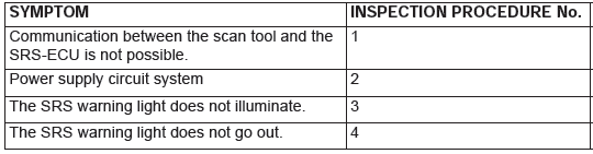
SYMPTOM PROCEDURES
Inspection procedure 1: Communication between the Scan Tool and the SRS-ECU is not possible.
TECHNICAL DESCRIPTION (COMMENT)
If the scan tool (M.U.T.-III Sub Assembly) can not communicate with the SRS system, the CAN bus lines may be defective. If the SRS system does not work, the SRS-ECU or its power supply circuit may be defective.
TROUBLESHOOTING HINTS (The most likely causes for this case:)
- Damaged wiring harness or connector
- Malfunction of the SRS-ECU
DIAGNOSIS
Required Special Tools:
- MB991958: Scan Tool (M.U.T.-III Sub Assembly)
- MB991824: Vehicle Communication Interface (V.C.I.)
- MB991827: M.U.T.-III USB Cable
- MB991910: M.U.T.-III Main Harness A (Vehicles with CAN communication system)
STEP 1. Using scan tool MB991958, diagnose the CAN bus line.
CAUTION To prevent damage to scan tool MB991958, always turn the ignition switch to the "LOCK" (OFF) position before connecting or disconnecting scan tool MB991958.
- Connect scan tool MB991958. Refer to "How to connect the Scan Tool (M.U.T.-III)".
- Turn the ignition switch to the "ON" position.
- Diagnose the CAN bus line.
- Turn the ignition switch to the "LOCK" (OFF) position.
Q: Is the CAN bus line found to be normal?
YES : Check and repair the power supply circuit system.
NO : Repair the CAN bus line.
Inspection procedure 2: Power supply circuit system
IG1 Power Supply Circuit
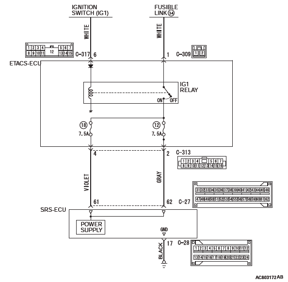
CIRCUIT OPERATION
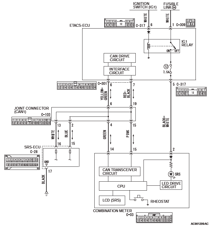
To SRS-ECU, the power is supplied from two independent circuits (fuse No. 12 and 18) via IG1 relay of ETACS-ECU.
If the power is not supplied to SRS-ECU, the communication between scan tool (M.U.T.-III Sub Assembly) and SRS-ECU cannot be established.
TROUBLESHOOTING HINTS (THE MOST LIKELY CAUSES FOR THIS CASE:)
- Damaged wiring harness or connector
- Charging system failed
- Malfunction of the SRS-ECU
- Malfunction of the ETACS-ECU
DIAGNOSIS
Required Special Tools:
- MB991958: Scan Tool (M.U.T.-III Sub Assembly)
- MB991824: Vehicle Communication Interface (V.C.I.)
- MB991827: M.U.T.-III USB Cable
- MB991910: M.U.T.-III Main Harness A (Vehicles with CAN communication system)
STEP 1. Power supply fuse check.
Q: Is the fuse in good condition?
YES : Go to Step 3.
NO : Go to Step 2
STEP 2. Check for a blown fuse.
- Replace the fuse.
- Turn the ignition switch to the "ON" position, wait for at least one minute and then turn the switch off.
- Check the fuse.
Q: Is the fuse in good condition?
YES : Go to Step 3.
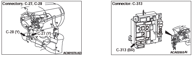
NO : Repair the wiring harness between the C-313 ETACS-ECU connector terminal No. 4/2 and the C-27 SRS-ECU connector terminal No. 61/62, and replace the power supply fuse.
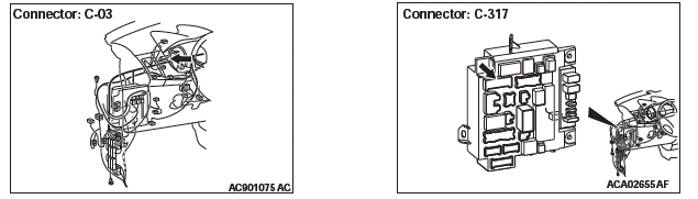
STEP 3. Resistance measurement at the-28 SRS-ECU connectors
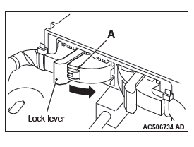
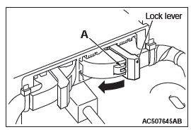
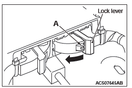
- While pushing the part "A" indicated in the figure of the harness side connector, turn the lock lever to the direction of the arrow to release the lock lever, and disconnect the C-28 SRS-ECU connectors.
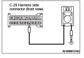
- Take the measurements below at the C-28 wiring harness side connectors.
- Continuity between C-28 wiring harness side connector terminal No. 17 and body ground OK: Continuity (Less than 2 ohms)
Q: Is the check result normal?
YES : Go to Step 4.
NO : Repair the wiring harness between C-28 SRS-ECU connector terminal No. 17 and body ground.
STEP 4. Measure the voltage at the C-27 SRS-ECU connector.
- Disconnect the negative battery terminal.
- While pushing the part "A" indicated in the figure of the harness side connector, turn the lock lever to the direction of the arrow to release the lock lever, and disconnect the C-27 SRS-ECU connector.
- Connect the negative battery terminal.
- Ignition switch: ON
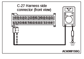
- Take the measurements below at the C-27 harness side connector.
- Voltage between terminal No. 61, 62 and body ground OK: 9 V or more
Q: Is the measured voltage within the specified range?
YES : Go to Step 6.
NO : Go to Step 5.
STEP 5. Check the harness for open circuit between SRS-ECU connector C-27 (terminal No.61 and 62) and the ETACS-ECU connector C-313 (terminal No.4 and 2).
- Disconnect the negative battery terminal.
- While pushing the part "A" indicated in the figure of the harness side connector, turn the lock lever to the direction of the arrow to release the lock lever, and disconnect the C-27 SRS-ECU connector.
- Disconnect the ETACS-ECU connector C-313.
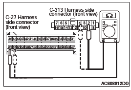
- Check for continuity between the following terminals. It should be less than 2 ohms.
<Fuse No.12>
- SRS-ECU connector C-27 (terminal No.62) and the ETACS-ECU connector C-313 (terminal No.2)
<Fuse No.18>
- SRS-ECU connector C-27 (terminal No.61) and the ETACS-ECU connector C-313 (terminal No.4)
Q: Does continuity exist?
YES : Replace the ETACS-ECU.
NO : Repair the harness wire between SRS-ECU connector C-27 and the ETACS-ECU connector C-313.
STEP 6. Retest the system
Q: Is the communication between scan tool and SRS-ECU possible?
YES : Intermittent malfunction (Refer to GROUP 00, How to Use Troubleshooting/Inspection Service Points −How to Cope with Intermittent Malfunction.) NO : Replace SRS-ECU.
Inspection procedure 3:The SRS Warning Light does not Illuminate.
SRS Warning Light Circuit
CIRCUIT OPERATION
- The SRS warning light illuminates when the ignition switch is turned to the "ON" position and goes out after approximately seven seconds if there is not a malfunction in the SRS system.
- SRS-ECU sends the SRS warning light signal to the combination meter via the CAN communication.
- As a cause, the failure of CAN bus line, combination meter, or SRS-ECU is suspected.
TROUBLESHOOTING HINTS
- Damaged wiring harness and connectors
- Combination meter malfunction
- Malfunction of SRS-ECU
DIAGNOSIS
Required Special Tools:
- MB991958: Scan Tool (M.U.T.-III Sub Assembly)
- MB991824: Vehicle Communication Interface (V.C.I.)
- MB991817: M.U.T.-III USB Cable
- MB991910: M.U.T.-III Main Harness A (Vehicles with CAN Communication System)
STEP 1. Using scan tool MB991958, diagnose the CAN bus line.
CAUTION To prevent damage to scan tool MB991958, always turn the ignition switch to the "LOCK" (OFF) position before connecting or disconnecting scan tool MB991958.
Use scan tool MB991958 to diagnose the CAN bus lines.
- Connect scan tool MB991958 to the data link connector.
- Turn the ignition switch to the "ON" position.
- Diagnose the CAN bus line.
Q: Is the check result satisfactory?
YES : Go to Step 2.
NO : Repair the CAN bus line.
STEP 2. Using scan tool MB991958, check actuator test.
Check the SRS-ECU actuator tests.
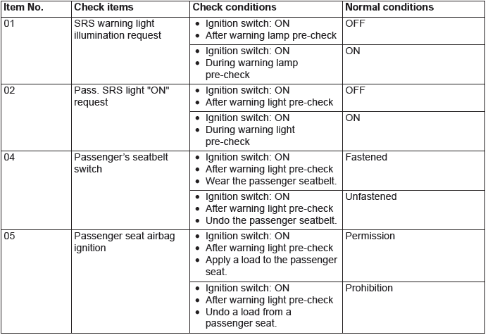
Item No. 01: SRS warning light Q: Does the SRS warning light turn on and off normally?
YES : Go to Step 3.
NO : Replace SRS-ECU.
STEP 3. Using scan tool MB991958, check actuator test.
Check the combination meter actuator tests.
Item No. 07: Indicator 1 Q: Does the SRS warning light turn on and off normally?
YES : Go to Step 4.
NO : Replace the combination meter. (Refer to GROUP 54A, Combination Meter P.54A-118.)
STEP 4. Wiring harness inspection between C-317 ETACS-ECU connector terminal No. 5 and C-03 combination meter connector terminal No. 2.
NOTE: Prior to the wiring harness inspection, check the ETACS-ECU connectors C-317 and combination meter connector C-03, and repair if necessary.
- The SRS warning light inspection for open and short circuit
Q: Is the check result normal?
YES : If other systems are normally operated, replace the combination meter. (Refer to GROUP 54A, Combination Meter P.54A-118.) NO : Repair the wiring harness.
Inspection procedure 4: The SRS Warning Light does not Go Out.
CIRCUIT OPERATION
- The SRS warning light illuminates when the ignition switch is turned to the "ON" position and goes out after approximately seven seconds if there is not a malfunction in the SRS system.
- SRS-ECU sends the SRS warning light signal to the combination meter via the CAN communication.
- As a cause, the failure of CAN bus line, combination meter, or SRS-ECU is suspected.
TROUBLESHOOTING HINTS
- Damaged wiring harness and connectors
- Combination meter malfunction
- Malfunction of SRS-ECU
DIAGNOSIS
Required Special Tools:
- MB991958: Scan Tool (M.U.T.-III Sub Assembly)
- MB991824: Vehicle Communication Interface (V.C.I.)
- MB991817: M.U.T.-III USB Cable
- MB991910: M.U.T.-III Main Harness A (Vehicles with CAN Communication System)
STEP 1. Using scan tool MB991958, diagnose the CAN bus line.
CAUTION To prevent damage to scan tool MB991958, always turn the ignition switch to the "LOCK" (OFF) position before connecting or disconnecting scan tool MB991958.
Use scan tool MB991958 to diagnose the CAN bus lines.
- Connect scan tool MB991958 to the data link connector.
- Turn the ignition switch to the "ON" position.
- Diagnose the CAN bus line.
Q: Is the check result satisfactory?
YES : Go to Step 2.
NO : Repair the CAN bus line.
STEP 2. Recheck of the SRS warning light.
- Connect the negative battery terminal.
- Ignition switch: ON
Q: Does the SRS warning light illuminate for approximately 7 seconds and then go out after the ignition switch is turned to the "ON" position?
YES : There is an intermittent malfunction such as poor engaged connector(s) or open circuit (Refer to GROUP 00, How to Cope with Intermittent Malfunction).
NO : Go to Step 3.
STEP 3. Using scan tool MB991958, check actuator test.
Check the combination meter actuator tests.
Item No. 07: Indicator 1 Q: Does the SRS warning light turn on and off normally?
YES : Go to Step 4.
NO : Replace the combination meter. (Refer to GROUP 54A, Combination Meter P.54A-118.)
STEP 4. Recheck for diagnostic trouble code.
Check again if the DTC is set.
- Erase the DTC.
- Turn the ignition switch to the "ON" position.
- Check if the DTC is set.
- Turn the ignition switch to the "LOCK" (OFF) position.
Q: Is DTC set?
YES : Troubleshoot for the relevant DTC.
NO : Go to Step 5
STEP 5. Recheck of the SRS warning light.
- Connect the negative battery terminal.
- Ignition switch: ON
Q: Does the light stay on?
YES : Replace the SRS-ECU.
NO : The procedure is complete.
DATA LIST REFERENCE TABLE
DATA LIST OUTPUT
The following items can be read by the scan tool from the SRS-ECU input data.
The following items can be read by the scan tool from the occupant classification-ECU input data.
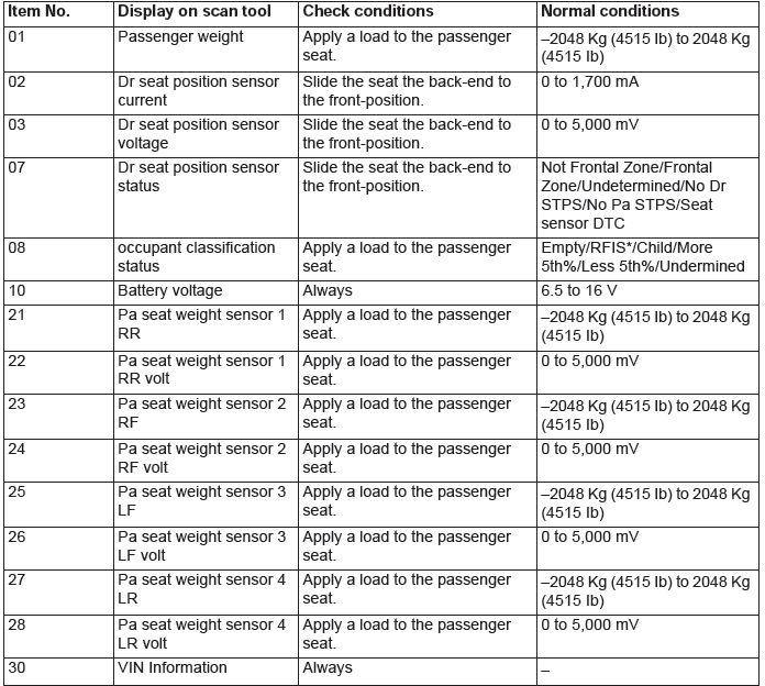
NOTE: *: Radio Frequency Integrated Circuit
ACTUATOR TEST REFERENCE TABLE
The scan tool activates the following actuators for testing.

FAIL-SAFE FUNCTION REFERENCE TABLE
If the SRS-ECU determines that the following parts are defective, the SRS-ECU operates the SRS warning light and controls as follows.
- If the seat slide sensor is defective, the SRS-ECU determines that the seat is in its backward position and controls the air bag.
- If the occupant classification sensor or the occupant classification-ECU is defective, the SRS-ECU determines that the occupant classification is class 2 [The occupant classification sensor detects 30 kg (66 pounds) or more.] and controls the air bag and the passenger's air bag OFF indicator light.
ACCURACY CHECK OF OCCUPANT CLASSIFICATION SENSOR
The scan tool can be used to perform the next function.
- Zero-Calibration & System Test
Special Tools
Test Equipment
READ NEXT:
 Post-collision Diagnosis
To inspect and service the SRS after a collision (whether or not
the air bags have deployed), perform the following steps.
SRS-ECU MEMORY CHECK
Required Special Tool:
MB991958: Scan Tool (M.U.T.-III
Air Bag Module(s) and Clock Spring
REMOVAL AND INSTALLATION
WARNING
Never attempt to disassemble or repair the air bag modules or
clock spring. If faulty,
replace it.
Do not drop the air bag modules or clock spring or allow conta
Side Impact Sensor
REMOVAL AND INSTALLATION
WARNING
Never attempt to disassemble or repair the side impact sensor. If
faulty, replace it.
Do not drop or subject the side impact sensor to impact or
vibration. Repl
SEE MORE:
Electric window control
The electric windows can only be operated with the ignition switch in the “ON”
position.
WARNING:
● Before operating the electric window control, make sure that nothing is capable
of being trapped (head, hand, finger, etc.).
● Never leave the vehicle without removing the key.
Manual A/C Diagnosis
INTRODUCTION TO HEATER, AIR CONDITIONING AND VENTILATION DIAGNOSIS
Air is drawn into the heater assembly from either the
outside, or from the inside of the passenger cabin if
DEFROST, maximum cooling or RECIRCULATION
are selected. The air is then forced through the evaporator
where heat is removed,
