Mitsubishi Outlander: Air Bag Module(s) and Clock Spring
REMOVAL AND INSTALLATION
WARNING
- Never attempt to disassemble or repair the air bag modules or clock spring. If faulty, replace it.
- Do not drop the air bag modules or clock spring or allow contact
with water, grease or oil.
Replace it if a dent, crack, deformation or rust is detected.
- The air bag modules should be stored on a flat surface with the
pad cover facing upward.
Do not place anything on top of it.
- Do not expose the air bag modules to temperatures over 93ºC (200ºF).
- After the air bag deployment, replace the air bag module with a new one. Also, check the clock spring, and replace with a new part if there is an abnormality.
- Wear gloves and safety glasses when handling air bags that have already deployed.
- Certain components of this vehicle, such as air bag modules, may contain perchlorate materials. Special handling may apply. For additional information, see www.dtsc.ca.gov/hazardouswaste/perchlorate.
- An undeployed air bag module should only be disposed of in accordance with the procedures.
- When removing and installing the front passenger seat, be sure to carry out accuracy check of the occupant classification sensor after the seat has been installed in the vehicle.
SIDE-AIR BAG MODULE
For removal and installation of the front seatback assembly with side-air bag module, refer to GROUP 52A, Front Seat.
DRIVER'S AIR BAG MODULE AND CLOCK SPRING
CAUTION On vehicles with ASC, always carry out steering wheel sensor calibration after the clock spring has been installed (Refer to GROUP 35C, On-vehicle Service-Steering Wheel Sensor Calibration). This is necessary because the ASC-ECU should update the steering neutral point.
Pre-removal operation
- Check that the front wheels are at the straight-ahead position.
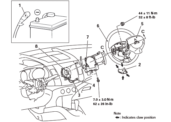
Driver's air bag module removal steps
- Negative (−) battery cable connection
- Cover
- Horn connector connection
- Driver's air bag module connector connection
- Driver's air bag module
Driver's air bag module installation steps
- Pre-installation inspection
- Driver's air bag module
- Driver's air bag module connector connection
- Horn connector connection
- Cover
- Negative (−) battery cable connection
- Post-installation inspection
Clock spring removal steps
- Negative (−) battery cable connection
- Cover
- Horn connector connection
- Driver's air bag module connector connection
- Driver's air bag module
- Steering wheel assembly
- Lower, upper column cover
- Paddle shift assembly <vehicles with paddle shift>
- Clock spring
Clock spring installation steps
Pre-installation inspection
- Clock spring
- Lower, upper column cover
- Paddle shift assembly <vehicles with paddle shift>
- Steering wheel assembly
- Driver's air bag module
- Driver's air bag module connector connection
- Horn connector connection
- Cover
- Negative (−) battery cable connection
- Post-installation inspection
- Steering wheel sensor calibration
Required Special Tools:
- MB991958: Scan Tool (M.U.T.-III Sub Assembly)
- MB991824:Vehicle Communication Interface( V.C.I.)
- MB991827:M.U.T.-III USB Cable
- MB991910:M.U.T.-III Main Harness A
- MB992006: Extra Fine Probe
- MB990803: Steering Wheel Puller
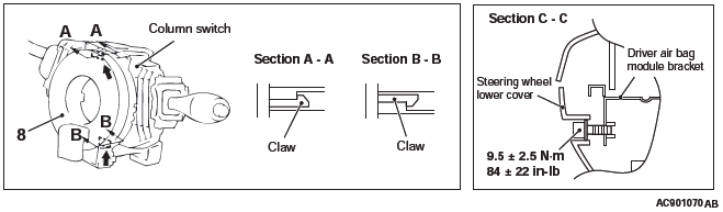
PASSENGER'S (FRONT) AIR BAG MODULE
Passenger's (front) air bag module removal steps
- Negative (−) battery cable connection
- Passenger's (front) air bag module connector
- Instrument panel assembly
- Passenger's (front) air bag module
Passenger's (front) Installation steps
- Pre-installation inspection
- Passenger's (front) air bag module
- Instrument panel assembly
- Passenger's (front) air bag module connector
- Negative (−) battery connection
- Post-installation inspection
Required Special Tools:
- MB991958: Scan Tool (M.U.T.-III Sub Assembly)
- MB991824: Vehicle Communication Interface( V.C.I.)
- MB991827: M.U.T.-III USB Cable
- MB991910: M.U.T.-III Main Harness A
- MB992006: Extra Fine Probe
REMOVAL SERVICE POINTS
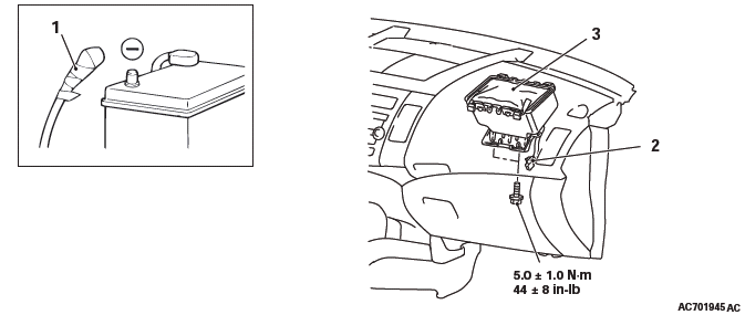
NEGATIVE (−) BATTERY CABLE DISCONNECTION
DANGER Wait at least 60 seconds after disconnecting the battery cable before doing any further work.
WARNING Battery posts, terminals and related accessories contain lead and lead compounds. WASH HANDS AFTER HANDLING.
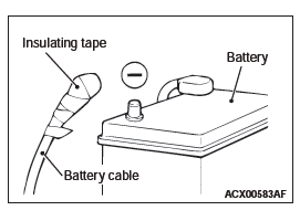
Disconnect the negative (−) battery cable from the battery and tape the terminal to prevent accidental connection and air bag(s) deployment.
COVER REMOVAL
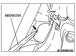
Insert the ornament remover (Special tool: MB990784) into the notch shown in the figure, and remove the cover.
DRIVER'S AIR BAG MODULE CONNECTOR REMOVAL
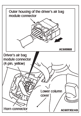
Slide the outer housing of the driver's air bag module connector in the arrow direction shown, and disconnect the connector.
DRIVER'S AIR BAG MODULE ASSEMBLY REMOVAL
WARNING
- The air bag module must not be measured with such equipment as an ohmmeter.
- The air bag module must not be disassembled.
- The removed air bag module should be stored in a clean, dry place with the deployment surface facing up.
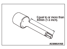
1. Using t-type long torx wrench (T30), a torx screw is loosened completely and removed <CANADA, Except vehicles with S-AWC>.
2. Loosen the torx screw and remove the air bag module assembly <Vehicles with S-AWC (Except CANADA)>.
STEERING WHEEL ASSEMBLY REMOVAL
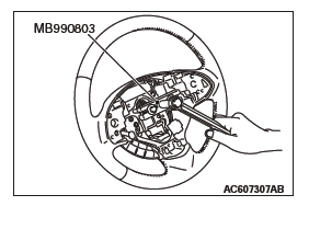
Use special tool MB990803 to remove the steering wheel.
CLOCK SPRING REMOVAL
WARNING The removed clock spring should be stored in a clean, dry place.
PASSENGER'S (FRONT) AIR BAG MODULE CONNECTOR REMOVAL
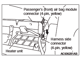
Slide the outer housing of the passenger's (front) air bag module connector in the arrow direction shown, and disconnect the connector.
PASSENGER'S (FRONT) AIR BAG MODULE REMOVAL
WARNING
- The air bag module must not be measured with such equipment as an ohmmeter.
- The air bag module must not be disassembled.
- The removed air bag module should be stored in a clean, dry place with the deployment surface facing up.
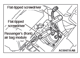
Insert a slotted (−) screwdriver or similar tool to the location shown in the figure. After disengaging the tabs, remove the front passenger's air bag module.
INSTALLATION SERVICE POINTS
PRE-INSTALLATION INSPECTION
WARNING Dispose of air bag modules only according to the specified procedure.
1. When installing the new air bag modules and clock spring, refer to "INSPECTION".
2. Connect the negative (−) battery cable.
CAUTION To prevent damage to scan tool MB991958, always turn the ignition switch to the "LOCK" (OFF) position before connecting or disconnecting scan tool MB991958.
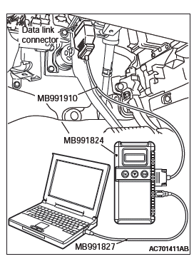
3. Connect scan tool MB991958 to the data link connector.
4. Turn the ignition switch to the "ON" position.
5. Check DTCs using scan tool MB991958 to ensure entire SRS operates properly.
At this time, check that no DTC except B1B02, B1B06, B1B0A and B1B0E are set.
DANGER Wait at least 60 seconds after disconnecting the battery cable before doing any further work.
WARNING Battery posts, terminals and related accessories contain lead and lead compounds. WASH HANDS AFTER HANDLING.
6. Turn the ignition switch to the "LOCK" (OFF) position.
Disconnect the negative (−) battery cable and tape the terminal to prevent accidental connection and air bags deployment.
CLOCK SPRING INSTALLATION
1. Check that the front wheels are at the straight-ahead position.
CAUTION
- If the center of the clock spring is not correctly aligned, the steering wheel may not be turned fully or the cable inside the clock spring may be broken, causing the SRS air bag to be inoperative or operated incorrectly.
- When aligning the clock spring neutral position mark, perform with the clock spring independently. If performed with the steering wheel sensor installed, the steering wheel sensor may be damaged.
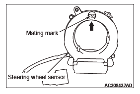
2. Align the mating marks of the clock spring.
Alignment of mating marks
- Turn the clock spring clockwise fully.
- Turn the clock spring counterclockwise approximately three and 1/2 turns to align the mating marks.
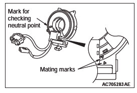
- Check that the white roller can be seen from the window
for checking the neutral point when the mating marks are
aligned.
NOTE: If the white roller cannot be seen or black roller can be seen, the neutral point is not aligned correctly.
- Install the clock spring to the column switch.
CAUTION Be sure to align the steering wheel sensor neutral position mark. If the neutral position marks are not aligned, the steering wheel operation may damage the steering wheel sensor.
3. Align the steering wheel sensor neutral position mark.
<Vehicle with ASC>
<Alignment of mating marks>
- When checking the neutral position check window of the steering wheel sensor, if an arrow can be seen, turn to the direction of the arrow, and align the neutral position mark as shown in the figure.
- Install the steering wheel sensor to the column switch assembly, maintaining the neutral position correctly.
- Install the column switch assembly to the vehicle, maintaining the neutral position correctly.
STEERING WHEEL ASSEMBLY/DRIVER'S AIR BAG MODULE ASSEMBLY INSTALLATION
CAUTION When installing the steering wheel and air bag module, ensure that the harness of the clock spring does not become caught or tangled.
1. Before installing the steering wheel and air bag module, turn the vehicle's front wheels to the straight-ahead position and align the mating marks of the clock spring.
2. After securing the steering wheel, turn the steering wheel all the way in both directions to confirm that the steering wheel rotation is normal.
DRIVER'S AIR BAG MODULE CONNECTOR/HORN CONNECTOR CONNECTION
Connect the connector securely and route the harnesses not to lie off the cover hole.
POST-INSTALLATION INSPECTION
1. Reconnect the negative (−) battery cable.
2. Turn the ignition switch to "ON" position.
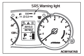
3. Does the "SRS" warning light illuminate for approximately seven seconds, and go out? 4. If yes, the SRS system is functioning properly.
INSPECTION
AIR BAG MODULE CHECK
DANGER Never attempt to measure the circuit resistance of the air bag modules (squib), even if you are using the specified tester. If the circuit resistance is measured with a tester, accidental air bag deployment will result, and possible serious personal injury.
WARNING If any component damage is found during the following inspection, replace the air bag module with a new one. Dispose of the old one according to the specified procedure.
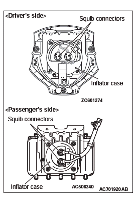
1. Check the pad cover for dents, cracks or deformation.
2. Check the connectors for damage, the terminals for deformation, and the harness for binding.
3. Check the air bag inflator case for dents, cracks or deformation.
4. Install the air bag module (driver's side) to the steering wheel and check fit and alignment with the steering wheel.
5. Install the air bag module (front passenger's side) to the instrument panel and front deck crossmember and check fit and alignment.
FRONT SEATBACK ASSEMBLY WITH SIDE-AIR BAG MODULE CHECK
DANGER Never attempt to measure the circuit resistance of the air bag module (squib), even if you are using the specified tester. If the circuit resistance is measured with a tester, accidental air bag deployment will result, and possible serious personal injury.
WARNING If any improper part is found during the following inspection, replace the front seatback assembly with a new one. Dispose of the old one according to the specified procedure.
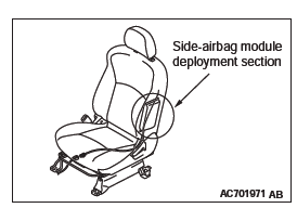
1. Check the air bag module deployment section for dents or deformation.
2. Check the connector for damage, the terminals for deformation, and the harness for binding.
CLOCK SPRING CHECK
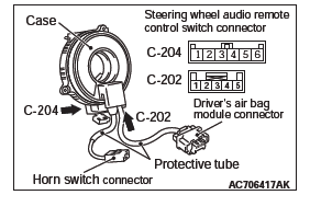
If any malfunction is found in the following inspections, replace the clock spring with a new one.
1. Check the connectors and protective tube for damage, and the terminals for deformation.
2. Visually check the case for damage.
3. Check that the continuity exists between the following connector terminals.
- C-204 connector terminal 1 and horn switch connector
- C-204 connector terminal 2 and C-202 connector terminal 5
- C-204 connector terminal 3 and C-202 connector terminal 4
- C-204 connector terminal 4 and C-202 connector terminal 3
- C-204 connector terminal 5 and C-202 connector terminal 2
- C-204 connector terminal 6 and C-202 connector terminal 1
CAUTION Do not directly insert a probe, etc. into the terminal from the front of the connector.
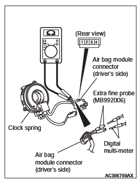
4. Insert the special tool (MB992006) from behind the air bag module connector of the C-205 driver's side.
5. Connect the circuit tester to the special tool as shown in the figure, and check the continuity among terminal No. 1 − 2 or No. 3 − 4.
READ NEXT:
 Side Impact Sensor
REMOVAL AND INSTALLATION
WARNING
Never attempt to disassemble or repair the side impact sensor. If
faulty, replace it.
Do not drop or subject the side impact sensor to impact or
vibration. Repl
Curtain Air Bag Module(s)
REMOVAL AND INSTALLATION
WARNING
Never attempt to disassemble or repair the curtain air bag
modules. If faulty, replace it.
Do not drop the curtain air bag modules or allow contact with
water,
Air Bag Module and Seat Belt Pre-tensioner Disposal Procedures
Before disposing of an air bag or a vehicle equipped with an air
bag, follow the procedures below to deploy the air bag.
UNDEPLOYED AIR BAG MODULE DISPOSAL
Required Special Tools:
MB992102: Air Bag
SEE MORE:
Engine oil
To check and refill engine oil
The engine oil used has a significant effect on the engine’s performance, service
life and startability. Be sure to use oil of the recommended quality and appropriate
viscosity.
All engines consume a certain amount of oil during normal operation. Therefore,
Ignition Switch
SPECIAL TOOLS
TROUBLESHOOTING
STANDARD FLOW OF DIAGNOSTIC TROUBLE SHOOTING
Refer to Group 00 − Contents of troubleshooting.
DIAGNOSIS FUNCTION
HOW TO CONNECT THE SCAN TOOL (M.U.T.-III)
Required Special Tools:
MB991958: Scan Tool (M.U.T.-III Sub Assembly)
MB991824: Vehicle Communication
