Mitsubishi Outlander: Ignition Switch
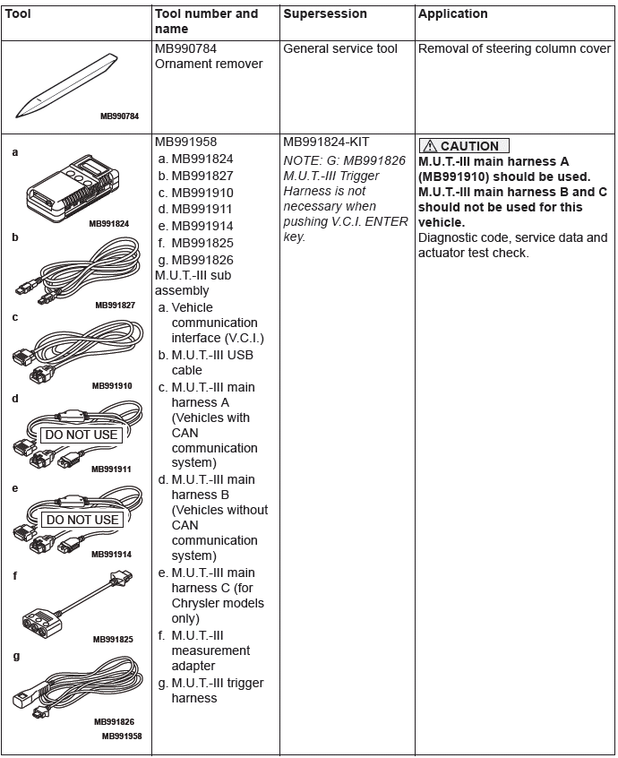
SPECIAL TOOLS
TROUBLESHOOTING
STANDARD FLOW OF DIAGNOSTIC TROUBLE SHOOTING
Refer to Group 00 − Contents of troubleshooting.
DIAGNOSIS FUNCTION
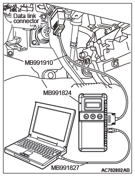
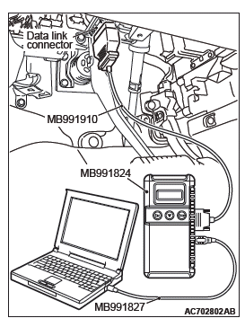
HOW TO CONNECT THE SCAN TOOL (M.U.T.-III)
Required Special Tools:
- MB991958: Scan Tool (M.U.T.-III Sub Assembly)
- MB991824: Vehicle Communication Interface (V.C.I.)
- MB991827: M.U.T.-III USB Cable
- MB991910: M.U.T.-III Main Harness A (Vehicles with CAN communication system)
CAUTION To prevent damage to scan tool MB991958, always turn the ignition switch to the "LOCK" (OFF) position before connecting or disconnecting scan tool MB991958.
1. Ensure that the ignition switch is at the "LOCK" (OFF) position.
2. Start up the personal computer.
3. Connect special tool MB991827 to special tool MB991824 and the personal computer.
4. Connect special tool MB991910 to special tool MB991824.
5. Connect special tool MB991910 to the data link connector.
6. Turn the power switch of special tool MB991824 to the "ON" position.
NOTE: When special tool MB991824 is energized, special tool MB991824 indicator light will be illuminated in a green color.
7. Start the M.U.T.-III system on the personal computer.
NOTE: Disconnecting scan tool MB991958 is the reverse of the connecting sequence, making sure that the ignition switch is at the "LOCK" (OFF) position.
HOW TO READ AND ERASE DIAGNOSTIC TROUBLE CODES
Required Special Tools:
- MB991958: Scan Tool (M.U.T.-III Sub Assembly)
- MB991824: Vehicle Communication Interface (V.C.I.)
- MB991827: M.U.T.-III USB Cable
- MB991910: M.U.T.-III Main Harness A (Vehicles with CAN communication system)
CAUTION To prevent damage to scan tool MB991958, always turn the ignition switch to the "LOCK" (OFF) position before connecting or disconnecting scan tool MB991958.
NOTE: If the battery voltage is low, diagnostic trouble codes will not be set. Check the battery if scan tool MB991958 does not display.
1. Connect scan tool MB991958 to the data link connector.
2. Turn the ignition switch to the "ON" position.
3. Select "System select" from the start-up screen.
4. Select "From 2006 MY" of "Model Year". When the "Vehicle Information" is displayed, check the contents.
5. Select "ETACS" from "System List", and press the "OK" button.
NOTE: When the "Loading Option Setup" list is displayed, check the applicable item.
6. Select "Diagnostic Trouble Code". to read the DTC.
7. If a DTC is set, it is shown.
8. Choose "Erase DTCs" to erase the DTC.
HOW TO DIAGNOSE THE CAN BUS LINES
Required Special Tools:
- MB991958: Scan Tool (M.U.T.-III Sub Assembly)
- MB991824: Vehicles Communication Interface (V.C.I.)
- MB991827: M.U.T.-III USB Cable
- MB991910: M.U.T.-III Main Harness A (Vehicles with CAN communication system)
1. Connect scan tool MB991958 to the data link connector.
2. Turn the ignition switch to the "ON" position.
3. Select "CAN bus diagnosis" from the start-up screen.
4. When the vehicle information is displayed, confirm that it matches the vehicle being diagnosed.
- If they match, go to step 8.
- If not, go to step 5.
5. Select the "view vehicle information" button.
6. Enter the vehicle information and select the "OK" button.
7. When the vehicle information is displayed, confirm again that it matches the vehicle being diagnosed.
- If they match, go to step 8.
- If not, go to step 5.
8. Select the "OK" button.
9. When the optional equipment screen is displayed, choose the one which the vehicle is fitted with, and then select the "OK" button.
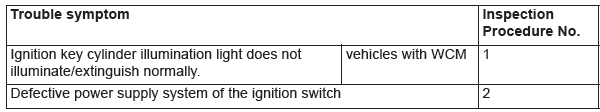
TROUBLE SYMPTOM CHART
SYMPTOM PROCEDURES
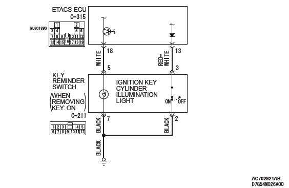
Inspection Procedure 1: Ignition key cylinder illumination light does not illuminate/extinguish normally. <vehicles with WCM>
CAUTION Whenever the ECU is replaced, ensure that the input and output signal circuits are normal.
Ignition Key Cylinder Illumination Light Circuit
OPERATION
The ETACS-ECU operates this function in accordance with the input signals below.
- Ignition switch (IG1)
- Key reminder switch
- Driver's door switch
- Driver's door lock actuator
TECHNICAL DESCRIPTION (COMMENT)
If this function does not work normally, these input signal circuit(s), the ignition key cylinder illumination light or the ETACS-ECU may be defective.
TROUBLESHOOTING HINTS
- The key reminder switch may be defective
- The driver's door switch may be defective
- The driver's door lock actuator may be defective
- The ignition key cylinder illumination light bulb may be defective
- The ETACS-ECU may be defective
- The wiring harness or connectors may have loose, corroded, or damaged terminals, or terminals pushed back in the connector
DIAGNOSIS
Required Special Tools:
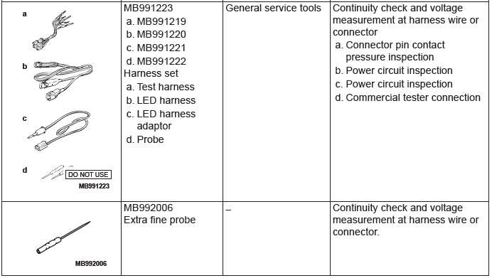
- MB992006: Extra fine probe
- MB991223: Harness set
- MB991958: Scan Tool (M.U.T.-III Sub Assembly)
- MB991824: Vehicle Communication Interface (V.C.I.)
- MB991827: M.U.T.-III USB Cable
- MB991910: M.U.T.-III Main Harness A (Vehicles with CAN communication system)
STEP 1. Using scan tool MB991958, read the diagnostic trouble code.
CAUTION To prevent damage to scan tool MB991958, always turn the ignition switch to the "LOCK" (OFF) position before connecting or disconnecting scan tool MB991958.
(1) Connect scan tool MB991958. Refer to "How to connect scan too (M.U.T.-III)".
(2) Turn the ignition switch to the "ON" position.
(3) Check whether the ETACS-ECU related DTC is set.
(4) Turn the ignition switch to the "LOCK" (OFF) position.
Q: Is the DTC set?
YES : Diagnose the ETACS-ECU.
NO : Go to Step 2.
STEP 2. Using scan tool MB991958, check data list.
Use the ETACS-ECU data list to check the signals related to the ignition key cylinder illumination light function.
- Turn the ignition switch to the "LOCK" (OFF) position.
- Remove the ignition key from the ignition key cylinder.
- Open the driver's door.
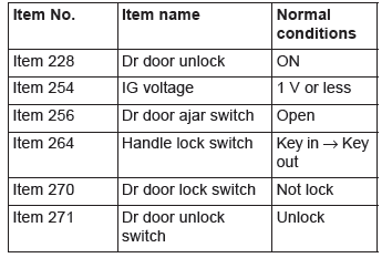
Q: Does scan tool MB991958 display the items "Dr door unlock", "Dr door ajar switch", and "Handle lock switch" as normal condition?
YES <Normal conditions are displayed for all the items.> : Go to Step 3.
NO <Normal condition is not displayed for item No.228.> : Troubleshoot the ETACS-ECU. Refer to GROUP 54A, Diagnosis - Inspection Procedure 4 "ETACS-ECU does not receive any signal from the front door lock actuator".
NO <Normal condition is not displayed for item No.254.> : Troubleshoot the ETACS-ECU. Refer to GROUP 54A, Diagnosis - Inspection Procedure 2 "ETACS-ECU does not receive any signal from the ignition switch (IG1)".
NO <Normal condition is not displayed for item No.256.> : Troubleshoot the ETACS-ECU. Refer to GROUP 54A, Diagnosis - Inspection Procedure 6 "ETACS-ECU does not receive any signal from the front the front door switch (RH)".
NO <Normal condition is not displayed for item No.264.> : Troubleshoot the ETACS-ECU. Refer to GROUP 54A, Diagnosis - Inspection Procedure 3 "ETACS-ECU does not receive any signal from key reminder switch".
NO <Normal condition is not displayed for item No. 270, 271.> : Troubleshoot the ETACS-ECU. Refer to GROUP 54A, Diagnosis - Inspection Procedure 4 "ETACS-ECU does not receive any signal from front door lock actuator".
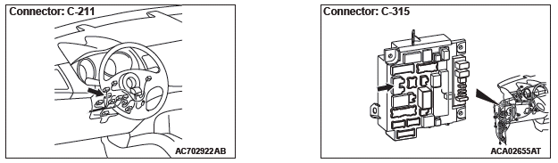
STEP 3. Check key reminder switch connector C-211, ETACS-ECU connector C-315 for loose, corroded or damaged terminals, or terminals pushed back in the connector.
Q: Is key reminder switch connector C-211, ETACS-ECU connector C-315 in good condition?
YES : Go to Step 4.
NO : Repair the damaged parts.
STEP 4.Check the Wiring harness between key reminder switch connector C-211 (terminal No. 5) and ETACS-ECU connector C-315 (terminal No. 18).
- Check the input/output line for open circuit.
Q: Is the check result normal?
YES : Go to Step 5.
NO : Repair the wiring harness between key reminder switch connector C-211 and ETACS-ECU connector C-315.
STEP 5. Check of ignition key cylinder illumination light bulb.
Q: Is the ignition key cylinder illumination light bulb in good condition?
YES : Go to Step 6.
NO : Replace the bulb of the ignition key cylinder illumination light.
STEP 6. Check the wiring harness between key reminder switch connector C-211 (terminal No. 7) and body ground.
- Check the ground line for open circuit.
Q: Is the check result normal?
YES : Go to Step 7.
NO : Repair the wiring harness between key reminder switch connector C-211 and body ground.
STEP 7. Retest the system.
Q: Does the ignition key cylinder illumination light illuminate/extinguish in good condition?
YES : The trouble can be an intermittent malfunction (Refer to GROUP 00, How to use Troubleshooting/inspection Service Points − How to Cope with Intermittent Malfunction).
NO : Replace the ETACS-ECU.
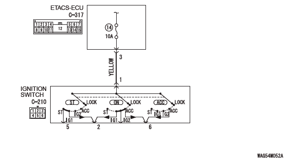
Inspection Procedure 2: Defective power supply system of the ignition switch
Ignition Switch Power Supply Circuit
TECHNICAL DESCRIPTION (COMMENT)
When the power supply system of ignition switch has a problem, none of the equipment and system connected to the ignition switch works even if the ignition switch is operated.
TROUBLESHOOTING HINTS
- The ignition switch may be defective
- The fuse No.14 may be defective
- The ETACS-ECU may be defective
- The wiring harness or connectors may have loose, corroded, or damaged terminals, or terminals pushed back in the connector
DIAGNOSIS
Required Special Tools:
- MB992006: Extra fine probe
- MB991223: Harness set
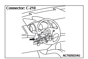
STEP 1. Check ignition switch connector C-210 for loose, corroded or damaged terminals, or terminals pushed back in the connector.
Q: Is ignition switch connector C-210 in good condition?
YES : Go to Step 2.
NO : Repair the defective connector.
STEP 2. Check the battery power supply circuit to the ignition switch. Measure the voltage at ignition switch connector C-210.
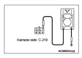
(1) Disconnect the connector, and measure at the wiring harness side.
(2) Measure the voltage between terminal 1 and ground.
- The voltage should measure approximately 12 volts (battery positive voltage).
Q: Is the measured voltage approximately 12 volts (battery positive voltage)?
YES : Go to Step 6.
NO : Go to Step 3.
STEP 3. Check the fuse No.14.
Q: Is the check result normal?
YES : Go to Step 4.
NO : Replace the fuse No.14. (Check that there is not a short to ground in the circuit of lower reaches before replacing. If there are any problems, replace the fuse after the circuit of lower reaches is repaired)
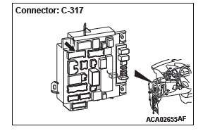
STEP 4. Check ETACS-ECU connector C-317 for loose, corroded or damaged terminals, or terminals pushed back in the connector.
Q: Is ETACS-ECU connector C-317 in good condition?
YES : Go to Step 5.
NO : Repair the damaged parts.
STEP 5. Check the Wiring harness between ignition switch connector C-210 (terminal No.1) and ETACS-ECU connector C-317 (terminal No.3).
- Check the battery power supply line for open circuit.
Q: Is the check result normal?
YES : Go to Step 7.
NO : Repair the wiring harness.
STEP 6. Check the ignition switch.
Remove the ignition switch. Then check continuity between the switch terminal.

Q: Is the ignition switch in good condition?
YES : Go to Step 7.
NO : Replace the ignition switch.
STEP 7. Retest the system.
Q: When the ignition switch is operated, do the equipment and system work normally?
YES : The trouble can be an intermittent malfunction (Refer to GROUP 00, How to use Troubleshooting/inspection Service Points − How to Cope with Intermittent Malfunction).
NO : Replace the ETACS-ECU.
ON-VEHICLE SERVICE
CHECK OF IGNITION KEY REMINDER WARNING FUNCTION (STEERING LOCK REMINDER TONE ALARM BY KOS)
1. Close the driver's door, unlock the steering lock, and turn the key (for the vehicle with KOS, the emergency key is inversely inserted into the keyless operation key) to the LOCK (OFF) position (the key is being inserted). <Vehicles with WCM and vehicles with KOS (When using the emergency key)>
2. Release the steering wheel lock with the driver's door closed, and turn the IG knob to the position other than the LOCK (OFF) position. <Vehicles with KOS (When not using the emergency key)>
3. Change the driver's door state from closed to open.
4. Check that the tone alarm sounds normally.
5. If a malfunction is found, carry out the troubleshooting.
REMOVAL AND INSTALLATION
CAUTION Before removing the steering wheel assembly, refer to GROUP 52B − Service Precautions and Air Bag Module and Clock Spring <Vehicles with WCM>.
CAUTION After the installation, perform a calibration for the ASC-ECU to learn the steering wheel sensor neutral point (Refer to GROUP 35C, On-vehicle Service − Steering Wheel Sensor Calibration).
<Vehicles with WCM and ASC>
Pre-removal Operation
- Steering wheel straight-ahead position check. <Vehicles with WCM>
- Removal of steering wheel assembly (Refer to GROUP 37 − Steering Wheel). <Vehicles with WCM>
Post-installation Operation
- Installation of steering wheel assembly (Refer to GROUP 37 − Steering Wheel). <Vehicles with WCM>
- Steering wheel straight-ahead position check. <Vehicles with WCM>
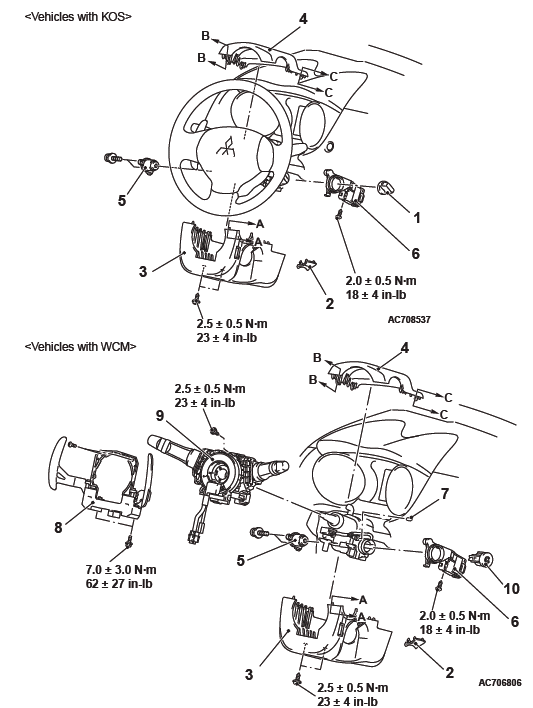
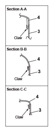
NOTE: Claw position is symmetrical
Removal Steps
- IG knob cap <Vehicles with KOS>
- Ignition key cover
- Steering column lower cover
- Steering column upper cover
- Ignition switch
- Wireless control module (WCM) <Vehicles with WCM>/Receiver antenna module <Vehicles with KOS>
- Key illumination bulb <Vehicles with WCM and paddle shift>
- Paddle shift assembly <Vehicles with WCM and paddle shift>
- Column switch assembly <Vehicles with WCM>
- Steering lock cylinder <Vehicles with WCM>
REMOVAL SERVICE POINT
STEERING LOCK CYLINDER REMOVAL <VEHICLES WITH WCM>
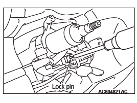
1. Insert the key into the steering lock cylinder, and turn the ignition key to the ACC position.
2. With using a cross-headed screw driver (small) or similar items to press in the lock pin, remove the ignition key, and then remove the steering lock cylinder.
INSTALLATION SERVICE POINT
WIRELESS CONTROL MODULE (WCM) <VEHICLES WITH WCM>/RECEIVER ANTENNA MODULE <VEHICLES WITH KOS> INSTALLATION
Check that the top claw of receiver antenna module is fixed securely to the boss of steering lock and the antenna is not floated on the key cylinder.
INSPECTION
IGNITION SWITCH CONTINUITY CHECK

With the ignition switch mounted to the vehicle, disconnect and check the ignition switch connection connector.

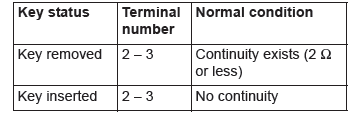
KEY REMINDER SWITCH CONTINUITY CHECK
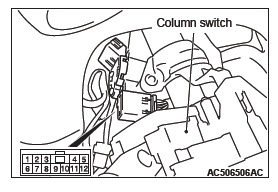
With the key reminder switch mounted to the vehicle, disconnect the key reminder switch connection connector, and then perform the continuity check.
READ NEXT:
 General Information
CONSTRUCTION DIAGRAM
<Except color liquid crystal display>
<Color liquid crystal display>
SERVICE SPECIFICATIONS
SPECIAL TOOLS
COMBINATION METERS DIAGNOSTIC
STANDARD FLOW OF DIAGNOSTI
Diagnostic Trouble Code Procedures
DTC B1200: Malfunction of odometer
TROUBLE JUDGMENT
If the odometer information, which is stored in the
combination meter, is abnormal when the ignition
switch at the ON position and the system voltag
SEE MORE:
Safe driving techniques
Driving safety and protection against injury cannot be fully ensured. However,
we recommend that you pay extra attention to the following:
Seat belts
Before starting the vehicle, make sure that you and your passengers have fastened
your seat belts.
Floor mats
WARNING:
● Keep floor m
Steering Column Shaft
Assembly
REMOVAL AND INSTALLATION
CAUTION
Before removing the steering wheel/driver's air bag module assembly,
refer to GROUP 52B − Service
Precautions and Driver's Air Bag Module Clock Spring.
After the installation, perform a calibration for the ASC-ECU to
learn the steering wheel sensor
ne
