Mitsubishi Outlander: Post-collision Diagnosis
To inspect and service the SRS after a collision (whether or not the air bags have deployed), perform the following steps.
SRS-ECU MEMORY CHECK
Required Special Tool:
- MB991958: Scan Tool (M.U.T.-III Sub Assembly)
- MB991824:Vehicle Communication Interface (V.C.I.)
- MB991827:M.U.T.-III USB Cable
- MB991910:M.U.T.-III Main Harness A (Vehicles with CAN Communication System)
CAUTION To prevent damage to scan tool MB991958, always turn the ignition switch to the "LOCK" (OFF) position before connecting or disconnecting scan tool MB991958.
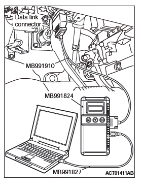
1. Connect scan tool MB991958 to the data link connector (16-pin).
2. Read (and write down) all displayed diagnostic trouble codes.
NOTE: If the battery power supply has been disconnected or disrupted by the collision, scan tool MB991958 cannot communicate with the SRS-ECU. Check the battery, then check and, if necessary, repair the front wiring harness and the instrument panel wiring harness before proceeding.
3. Read the data list (fault duration and how many times memories are erased), using scan tool MB991958.
4. Erase the diagnostic trouble codes, and then turn the ignition switch to the LOCK (OFF) position.
5. Wait for at least one second, and then turn the ignition switch to the ON position again.
6. After waiting 15 seconds or more, note all displayed diagnostic trouble codes.
REPAIR PROCEDURE
WHEN FRONT AIR BAGS DEPLOY IN A COLLISION.
1. Replace the following parts with new ones:
- SRS-ECU
- Air bag modules
- Seat belt with pre-tensioner
- Front impact sensors
- Front passenger's air bag lid assembly
- Front passenger's seat cushion frame assembly (Occupant classification-ECU and weight sensor)
2. Check the following parts and replace if there are any malfunctions:
- Clock spring
- Driver's seat cushion frame assembly (seat slide sensor)
- Seat belt switch
- Steering wheel, steering column shaft assembly
- Check the wiring harness (built into the steering wheel) and connectors for damage, and terminals for deformation.
- Install the air bag module to check fit and alignment with the steering wheel.
- Check the steering wheel for noise, binding or difficult operation and excessive free play.
- Check the steering column shaft shock absorbing mechanism.
3. Check the wiring harnesses for binding, the connectors for damage, poor connections, and the terminals for deformation.
WHEN SIDE AND CURTAIN AIR BAGS DEPLOY IN A COLLISION.
1. Replace the following parts with new ones:
- SRS-ECU
- Side impact sensors (front and rear)
- Front seatback assembly, front passenger's seat cushion frame assembly (Occupant classification-ECU and weight sensor)
- Curtain air bag module
2. Check the wiring harnesses for binding, the connectors for damage, poor connections, and the terminals for deformation
WHEN CURTAIN AIR BAGS DEPLOY IN A COLLISION.
1. Replace the following parts with new ones:
- SRS-ECU
- Side impact sensors (rear)
- Front passenger's seat cushion frame assembly (Occupant classification-ECU and weight sensor)
- Curtain air bag module
2. Check the wiring harnesses for binding, the connectors for damage, poor connections, and the terminals for deformation.
WHEN CURTAIN AIR BAGS DEPLOY AND SEAT BELT PRE-TENSIONER OPERATE IN A COLLISION.
1. Replace the following parts with new ones:
- SRS-ECU
- Side impact sensors (rear)
- Front passenger's seat cushion frame assembly (Occupant classification-ECU and weight sensor)
- Seat belt with pre-tensioner
2. Check the wiring harnesses for binding, the connectors for damage, poor connections, and the terminals for deformation.
WHEN AIR BAGS DO NOT DEPLOY IN LOW-SPEED COLLISION.
Check the SRS components. If the SRS components are showing any visible damage such as dents, cracks, or deformation, replace them with new ones. Concerning parts removed for inspection, replacement with new parts and cautionary points for working, refer to appropriate INDIVIDUAL COMPONENT SERVICE.
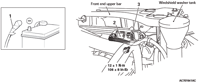
FRONT IMPACT SENSOR
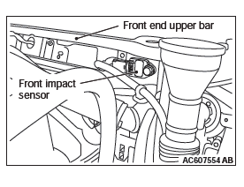
1. Check the front end upper bar for distortion and rust.
2. Check the front impact sensor for dents, cracks, deformation or rust.
3. Check the front impact sensor wiring harness for binding, check the connector for damage, and check the terminals for deformation.
NOTE: The illustration shows the side impact sensor (RH).
The position of the side impact sensor (LH) is symmetrical to this.
SRS-ECU
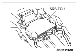
1. Check the SRS-ECU case and brackets for dents, cracks or deformation.
2. Check the connector for damage, and the terminals for deformation.
3. Check the installation of the SRS-ECU and its bracket.
AIR BAG MODULES
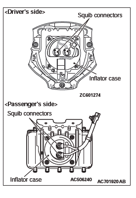
1. Check the pad cover for dents, cracks or deformation.
2. Check the connector for damage, terminal deformities, and the harness for binding.
3. Check the air bag inflator case for dents, cracks or deformities.
4. Install the air bag module (driver's side) to the steering wheel to check installation or alignment with the steering wheel.
5. Install the air bag module (front passenger's side) to the instrument panel and front deck crossmember to check installation or alignment.
FRONT SEATBACK ASSEMBLY (SIDE-AIR BAG MODULE)
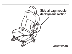
1. Check the air bag module deployment section for dents or deformation.
2. Check that there is no connector damage, bent terminals or harness crimping.
CLOCK SPRING
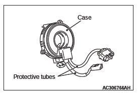
1. Check the clock spring connectors and protective tube for damage, and the terminals for deformation.
2. Visually check the case for damage.
SIDE IMPACT SENSOR
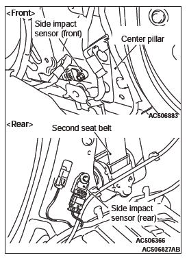
1. Check that there is no bending or corrosion in the center pillar and quarter panel.
2. Check that there is no denting, breakage or bending of the side impact sensor.
3. Check that there is no harness crimping, connector damage or bent terminals.
NOTE: The illustration shows the side impact sensor (RH).
The position of the side impact sensor (LH) is symmetrical to this.
SEAT SLIDE SENSOR
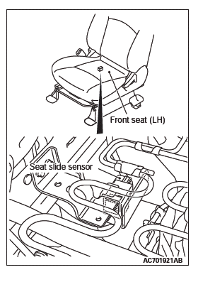
1. Check that there is no connector damage, bent terminals or harness crimping.
2. Check the installation of the seat slide sensor.
OCCUPANT CLASSIFICATION-ECU AND WEIGHT SENSOR
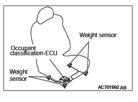
1. Check the occupant classification-ECU case and weight sensor for dents, cracks or deformation.
2. Check the connector for damage, and the terminals for deformation.
3. Check the installation of the occupant classification-ECU and weight sensor.
4. Check the diagnostic trouble code of occupant classification-ECU and replace the seat cushion frame assembly <passenger's side> if DTC B1BA7 is set.
CURTAIN AIR BAG MODULE
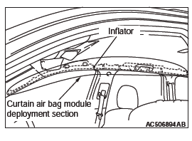
1. Check that the curtain air bag deployment part of the headlining is normal.
2. Check the inflator surface for cracks, dents or deformations.
3. Check the connector for damage, the terminal for deformation, and the harness for binding.
STEERING WHEEL, STEERING COLUMN AND SHAFT ASSEMBLY
1. Check the wiring harness (built into the steering wheel) and the connectors for damage, and the terminals for deformation.
2. Install the air bag module to check fit or alignment with the steering wheel.
3. Check the steering wheel for noise, binding or difficult operation and excessive free play.
4. Check the steering column shaft shock absorbing mechanism (Refer to GROUP 37, On-Vehicle Service − Steering Column Shaft Assembly Shock Absorbing Mechanism Check).
SEAT BELT WITH PRE-TENSIONER
1. Check the seat belt for damage or deformation.
2. Check the seat belt with pre-tensioner for cracks or deformation.
3. Check that the unit is installed correctly to the vehicle body.
HARNESS CONNECTOR (FRONT WIRING HARNESS, INSTRUMENT PANEL WIRING HARNESS, AND FLOOR WIRING HARNESS)
Check the harnesses for binding, the connectors for damage, poor connection, and the terminals for deformation.
Individual Component Service
WARNING
- If heat damage occurs during paint work, remove
the SRS-ECU, the air bag modules, the clock
spring, front seats, impact sensor and the seat belt
with pre-tensioner. Recheck the SRS system operability
after reinstalling them.
- SRS-ECU, air bag module, clock spring, front seats, impact sensor: 93º C (200º F) or more
- Seat belt with pre-tensioner: 90ºC (194º F) or more
- If the SRS components are removed for the purpose of inspection, sheet metal repair, painting, etc., they should be stored in a clean, dry place until they are reinstalled.
If the SRS components are to be removed or replaced as a result of maintenance, diagnosis, etc., follow the appropriate procedure in this section.
On-vehicle Service
ACCURACY CHECK OF OCCUPANT CLASSIFICATION SENSOR
CAUTION The following precaution must be observed when executing accuracy testing and calibration.
- Perform the occupant classification sensor calibration at room temperature. (Proposal: 20 +- 15ºC (68 +- 27º F) ) (Before the calibration, place the occupant classification sensor more than 30 minutes at room temperature.)
- Do not apply any load or vibration while the weight check and the calibration is performed.
- Perform the weight check and the calibration after seat components are all assembled.
CAUTION To prevent damage to scan tool MB991958, always turn the ignition switch to the "LOCK" (OFF) position before connecting or disconnecting scan tool MB991958.
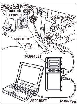
1. Connect scan tool MB991958 to the data link connector.
2. To execute accuracy check and calibration, operate scan tool MB991958 (M.U.T.-III Sub Assembly) as follows.
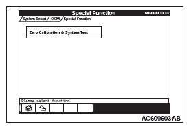
- Select "OCM".
- Select "Special Function".
- Select "Zero Calibration & System Test".
- The start of the zero calibration.
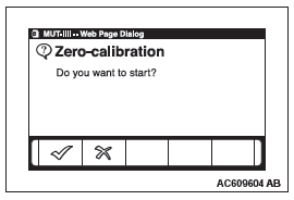
- The execution check of the zero calibration.
- The zero calibration has been completed when the screen as shown in the illustration is displayed. The OK button is pushed and it progresses to the next.
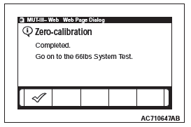
- The start of 66 lbs system test.
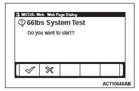
- The execution check of the 66 lbs system test.
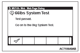
- The 66 lbs system test has been completed when the screen as shown in the illustration is displayed. The OK button is pushed and it progresses to the next.
- The start of 0 lbs system test.
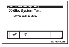
- The execution check of the 0 lbs system test.
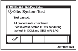
-
The 0 lbs system test has been completed when the screen as shown in the illustration is displayed.
Front Impact Sensors
REMOVAL AND INSTALLATION
WARNING
- Never repair or disassemble the front impact sensor. If faulty, replace it.
- Handle the front impact sensors very carefully, taking care not to drop them. They must be replaced if they are dropped.
- Replace the sensors with new ones after the air bag has deployed.
Pre-removal Operation
- Turn the ignition key to the "LOCK" (OFF) position.
Removal steps
- Negative (−) battery cable connection
- Front impact sensor connector connection
- Front impact sensor
Installation steps
- Pre-installation inspection
- Front impact sensor
- Front impact sensor connector connection
- Negative(−) battery cable connection
- Post-installation inspection
NOTE: The figure indicates the right front impact sensor. The left impact sensor is symmetrical to this.
REMOVAL SERVICE POINTS
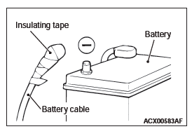
NEGATIVE (−) BATTERY CABLE DISCONNECTION
DANGER Wait at least 60 seconds after disconnecting the battery cable before doing any further work.
WARNING Battery posts, terminals and related accessories contain lead and lead compounds. WASH HANDS AFTER HANDLING.
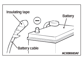
Disconnect the negative (−) battery cable from the battery and tape the terminal to prevent accidental connection and air bag(s) deployment.
FRONT IMPACT SENSOR CONNECTOR REMOVAL
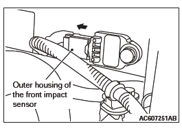
Side the outer housing of the front impact sensor connector in the arrow direction shown, and disconnect the connector.
INSTALLATION SERVICE POINTS
PRE-INSTALLATION INSPECTION
When installing the new front impact sensor, refer to "INSPECTION".
FRONT IMPACT SENSOR INSTALLATION
WARNING The SRS may not activate properly if a front impact sensor is not installed properly, which could result in serious injury or death to the vehicle's driver.
1. Securely connect the connector.
2. Position the front impact sensor facing toward the front of the vehicle as indicated by the arrow on the label, and install it securely.
POST-INSTALLATION INSPECTION
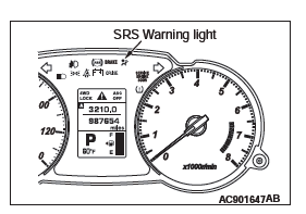
1. Reconnect the negative (−) battery cable.
2. Turn the ignition key to "ON" position.
3. Does the "SRS" warning light illuminate for approximately seven seconds, and then remain off for at least five seconds after turning "OFF"?
4. If yes, the SRS system is functioning properly.
INSPECTION
WARNING If a dent, crack, deformation or rust is detected, replace with a new sensor.
NOTE: For checking of the front impact sensor other than described below, refer to the section concerning SRS diagnosis.
1. Check the front impact sensor and bracket for dents, cracks or deformation.
2. Check the connector for damage, and terminals for deformation.
3. Check that there is no bending or corrosion in the radiator support panel.
SRS Control Unit (SRS-ECU)
REMOVAL AND INSTALLATION
DANGER The SRS-ECU adopts the rollover specification that the curtain air bag and seat belt pre-tensioner operate at the occurrence of rollover. Therefore, do not tilt the vehicle to the right and left with the IG ON or tilt the SRS-ECU to the right and left with the IG ON and the harness installed.
WARNING
- Never attempt to disassemble or repair the SRS-ECU. If faulty, replace it.
- Do not drop or subject the SRS-ECU to impact or vibration. If denting, cracking, deformation, or rust are discovered in the SRS-ECU, replace it with a new SRS-ECU.
- After deployment of an air bag, replace the SRS-ECU with a new one.
- Never use an ohmmeter on or near the SRS-ECU, and use only the special test equipment described here P.52B.
Pre-removal Operation
- Turn the ignition switch to the "LOCK" (OFF) position.
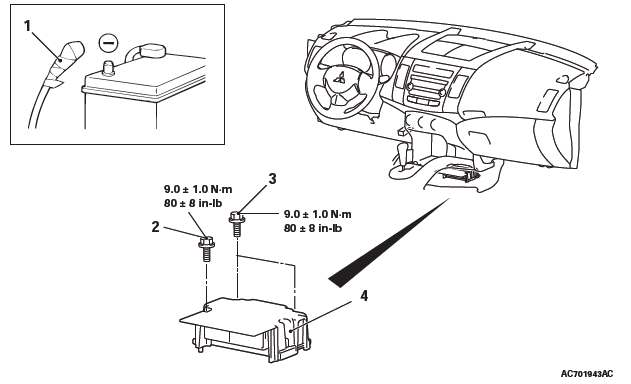
Removal steps
- Negative (−) battery cable connection
- Lower side cover
- SRS-ECU mounting bolt (ground bolt)
- SRS-ECU mounting bolt
- SRS-ECU
Installation steps
- SRS-ECU
- SRS-ECU mounting bolt
- SRS-ECU mounting bolt (ground bolt)
- Lower side cover
- Negative (−) battery cable connection
- Post-installation inspection
REMOVAL SERVICE POINTS
NEGATIVE (−) BATTERY CABLE DISCONNECTION
DANGER Wait at least 60 seconds after disconnecting the battery cable before doing any further work.
WARNING Battery posts, terminals and related accessories contain lead and lead compounds. WASH HANDS AFTER HANDLING.
Disconnect the negative battery cable from the battery and tape the terminal to prevent accidental connection and deployment.
SRS-ECU REMOVAL
DANGER The SRS-ECU adopts the rollover specification that the curtain air bag and seat belt pre-tensioner operate at the occurrence of rollover. Therefore, do not tilt the vehicle to the right and left with the IG ON or tilt the SRS-ECU to the right and left with the IG ON and the harness installed.
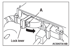
While pushing the part "A" indicated in the figure of the harness side connector, turn the lock lever to the direction of the arrow to release the lock lever.
INSTALLATION SERVICE POINTS
SRS-ECU INSTALLATION
WARNING The SRS may not activate if the SRS-ECU is not installed properly, which could result in serious injury or death to the vehicle's driver or front passenger.
SRS-ECU MOUNTING BOLT (GROUND BOLT) INSTALLATION
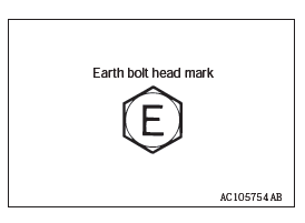
Check the head mark "E" and install the ground bolt.
POST-INSTALLATION INSPECTION
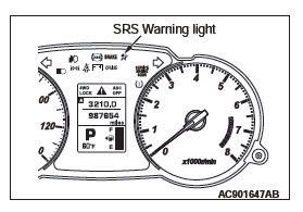
1. Reconnect the negative (−) battery cable.
2. Turn the ignition switch to the "ON" position.
3. Does the "SRS" warning light illuminate for approximately seven seconds, and then go out? 4. If yes, the SRS system is functioning properly.
INSPECTION
WARNING If a dent, crack, deformation or rust is discovered, replace the SRS-ECU with a new one.
- Check the SRS-ECU and brackets for dents, cracks or deformation.
- Check the SRS-ECU connector for damage, and the terminals for deformation.
READ NEXT:
 Air Bag Module(s) and Clock Spring
REMOVAL AND INSTALLATION
WARNING
Never attempt to disassemble or repair the air bag modules or
clock spring. If faulty,
replace it.
Do not drop the air bag modules or clock spring or allow conta
Side Impact Sensor
REMOVAL AND INSTALLATION
WARNING
Never attempt to disassemble or repair the side impact sensor. If
faulty, replace it.
Do not drop or subject the side impact sensor to impact or
vibration. Repl
Curtain Air Bag Module(s)
REMOVAL AND INSTALLATION
WARNING
Never attempt to disassemble or repair the curtain air bag
modules. If faulty, replace it.
Do not drop the curtain air bag modules or allow contact with
water,
SEE MORE:
Exhaust Manifold
REMOVAL AND INSTALLATION
<4WD>
Removal steps
Exhaust manifold bracket C
Exhaust manifold bracket A
Crankshaft position sensor cover
Crankshaft position sensor
O-ring
Exhaust manifold upper cover
Exhaust manifold lower cover
Exhaust manifold
Exhaust manifold gasket
<2WD - Except
Steering wheel audio remote controlswitches
The remote control switch is located on the left side of the steering wheel.
It can be used when the ignition switch is in the “ON” or “ACC” positions.
1- Volume up button.
2- Volume down button.
3- Power switch / mode selector button.
4- Seek up / track up / fast-forward button.
5-
