Mitsubishi Outlander: DTC P0741, P0742, P0743, P0748, P0753, P0758, P0763, P0768, P0815, P0816, P0826, P0846
DTC P0741: Torque Converter Clutch System (Stuck Off), P0742 Torque Converter Clutch System (Stuck ON)
DESCRIPTIONS OF MONITOR METHODS <P0741>
- When the input shaft speed sensor is normal, the
engine speed signal is normal, and within the
lock-up operation range, the slip speed of the
torque converter exceeds the specified value.
(P0741)
MONITOR EXECUTION <P0741>
- Driving with the lock-up activated
ONITOR EXECUTION CONDITIONS (OTHER MONITOR AND SENSOR) <P0741>
Other Monitor (There is no temporary DTC stored in memory for the item monitored below)
- Not applicable
Sensor (The sensor below is determined to be normal)
- Not applicable
LOGIC FLOW CHARTS (Monitor Sequence) <P0741>
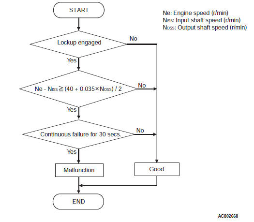
DTC SET CONDITIONS <P0741>
Check Conditions
- Lock-up status: engaging.
- Transmission range switch: D
Judgement Criteria
- Calculated slip (engine speed - input shaft speed): (40 + 0.035 × output shaft speed>)/2 or more. (30 seconds)
OBD-II DRIVE CYCLE PATTERN <P0741>
Driving at 55 km/h (34.2 mph) or more with the shift ranges of 3rd, 4th, 5th, and 6th gear. Maintain each shift range for 30 second or more.
DESCRIPTIONS OF MONITOR METHODS <P0742>
- When the input shaft speed sensor and the output
shaft speed sensor are normal at the "D"
range, the engine speed signal is normal, and
within the non-lock-up operation range, the
extremely low slip speed of the torque converter
is detected continuously for a specified time.
(P0742)
MONITOR EXECUTION <P0742>
- Transmission range: D range driving with the lock-up activated
MONITOR EXECUTION CONDITIONS (OTHER MONITOR AND SENSOR) <P0742>
Other Monitor (There is no temporary DTC stored in memory for the item monitored below)
- Not applicable
Sensor (The sensor below is determined to be normal)
- Not applicable
LOGIC FLOW CHARTS (Monitor Sequence) <P0742>
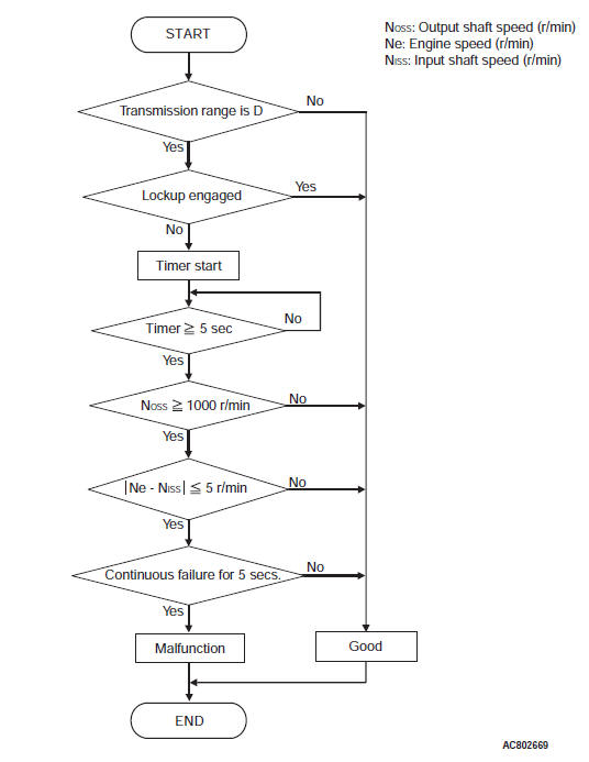
DTC SET CONDITIONS <P0742>
Check Conditions
- Output speed: more than 1,000 r/min.
- Lock-up status: disengaging.
- Transmission range switch position: D.
Judgement Criteria
- Calculated slip (engine speed - input shaft speed): 5 r/min or less. (5 seconds)
OBD-II DRIVE CYCLE PATTERN <P0742>
Driving at 55 km/h (34.2 mph) or less with the shift range of 3rd and 4th gear. Driving at 48 +- 2 km/h (29.8 +- 1.2 mph) with the 5th gear. Maintain each shift range for 1 second or more.
TROUBLESHOOTING HINTS (THE MOST LIKELY CAUSES FOR THIS CODE TO BE SET ARE:)
- Malfunction of the P0743: lock-up and low-reverse brake linear solenoid valve system circuit
- Malfunction of the P0712: transmission fluid temperature sensor system (short circuit)
- Malfunction of the P0713: transmission fluid temperature sensor system (open circuit)
- Poor installation of the engine and A/T (deviation to the axial direction)
- Malfunction of the torque converter
- Malfunction of the valve body assembly
DIAGNOSIS
STEP 1. Hydraulic pressure test
Q: Is the check result normal?
YES : Go to Step 2.
NO : Repair or replace the failure section.
STEP 2. Check the lock-up and low-reverse brake linear solenoid.
Check for P0743 (lock-up and low-reverse brake linear solenoid).
Q: Is the check result normal?
YES : Go to Step 3.
NO : Repair or replace the failure section.
STEP 3. Check the transmission fluid temperature sensor, input shaft speed sensor, and output shaft speed sensor.
Check the following DTCs: P0712 (transmission fluid temperature sensor (short circuit) ), P0713 (transmission fluid temperature sensor (open circuit) ), P0715 (input shaft speed sensor) and P0720 (output shaft speed sensor).
Q: Is the check result normal?
YES : Go to Step 4.
NO : Repair or replace the failure section.
STEP 4. Check the malfunction of CAN communication system.
Q: Are the DTC for CAN communication system malfunction (U0001, U0100, U0141, P1705, P1706) set?
YES : Repair or replace the failure section.
NO : Go to Step 5.
STEP 5. Check the TCM connector pin terminal and the connection status.
Q: Is the check result normal?
YES : Replace the TCM, and then go to Step 6.
NO : Repair or replace the failure section.
STEP 6. Erase the DTC code, and drive the vehicle for a while.
Check that the normal code is displayed.
Q: Is the check result normal?
YES : The procedure is complete.
NO : Go to Step 7.
STEP 7. Check the installation position of the engine and A/T.
Q: Is the check result normal?
YES : Replace the transaxle assembly.
NO : Repair or replace the failure section.
DTC P0743: Lock-up and Low-reverse Brake Linear Solenoid Valve System
Solenoid valve system circuit
DESCRIPTIONS OF MONITOR METHODS
- While driving with the sport mode (1st gear) or lock-up activated (2nd to 6th gear), when open or short circuit is detected for 5 seconds
- The control current of solenoid valve is abnormally large or small.
MONITOR EXECUTION
- Sport mode: 1st gear driving
- Transmission range: D (lock-up activated)
MONITOR EXECUTION CONDITIONS (OTHER MONITOR AND SENSOR)
Other Monitor (There is no temporary DTC stored in memory for the item monitored below)
- P0731: Malfunction of the 1st gear incorrect ratio
- P0732: Malfunction of the 2nd gear incorrect ratio
- P0733: Malfunction of the 3rd gear incorrect ratio
- P0734: Malfunction of the 4th gear incorrect ratio
- P0735: Malfunction of the 5th gear incorrect ratio
- P0729: Malfunction of the 6th gear incorrect ratio
- P0741: Malfunction of the Malfunction of the Torque converter clutch system (Stuck off)
Sensor (The sensor below is determined to be normal)
- Not applicable
LOGIC FLOW CHARTS (Monitor Sequence)
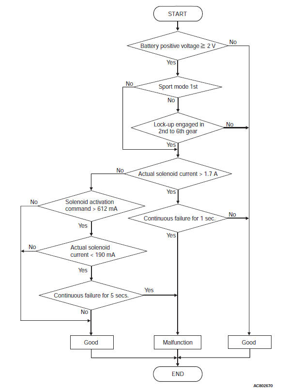
DTC SET CONDITIONS
Check Conditions <Circuit continuity ground>
- Sport mode: 1st or Lock-up status: engaging (2nd to 6th).
Judgment Criteria <Circuit continuity ground>
- Lock-up and low-reverse brake linear solenoid valve actual current: more than 1.7 A (1 second)
Check Conditions <Circuit continuity open>
- Sport mode: 1st or Lock-up status: engaging (2nd to 6th).
- Lock-up and low-reverse brake linear solenoid valve actual command: more than 612 mA
Judgment Criteria <Circuit continuity open>
- Lock-up and low-reverse brake linear solenoid valve actual current: less than 190 mA. (5 seconds)
OBD-II DRIVE CYCLE PATTERN
Drive with the sport mode (1st gear) for approximately 10 seconds, and then drive with the transmission range D, throttle valve opening 50% or less, and vehicle speed 60 km/h (37.3 mph) or more for approximately 10 seconds continuously.
TROUBLESHOOTING HINTS (THE MOST LIKELY CAUSES FOR THIS CODE TO BE SET ARE:)
- Malfunction of the lock-up and low-reverse brake linear solenoid valve system circuit
- Damaged harness or connector
- Malfunction of the TCM
- Malfunction of the lock-up and low-reverse brake linear solenoid valve (valve body assembly)
DIAGNOSIS
STEP 1. Check the TCM terminal voltage.
[C-37 TCM connector (vehicle side, connected) ]
Measure the voltage between the terminal No. 52 and body ground.
- Lock-up released: 0 V
- Lock-up engaged: 300 Hz
Q: Is the check result normal?
YES : Go to Step 5.
NO : Go to Step 2.
STEP 2. Check between the TCM connector and A/T control solenoid valve assembly connector.
Check for continuity between C-37 TCM connector and B-111 A/T control solenoid valve assembly connector.
NOTE: Prior to the wiring harness inspection, check the intermediate connectors A-12 and repair that if necessary.
- Between C-37 terminal No. 52 and B-111 terminal No. 4: Continuity exists.
When the continuity check result is OK, check that the wiring harness is not shorted to the body and other wiring harness.
Q: Is the check result normal?
YES : Go to Step 3.
NO : Repair or replace the failure section.
STEP 3. Check the lock-up and low-reverse brake linear solenoid.
Q: Is the check result normal?
YES : Go to Step 6.
NO : Go to Step 4.
STEP 4. Check between the A/T control solenoid valve assembly connector and the lock-up and low-reverse brake linear solenoid valve connector.
Check for continuity between the A/T control solenoid valve assembly connector and the lock-up and low-reverse brake linear solenoid valve connector terminals.
- Between C-111 terminal No. 4 and the lock-up and low-reverse brake linear solenoid valve: Continuity exists.
Q: Is the check result satisfactory?
YES : Replace the valve body assembly.
NO : Repair or replace the failure section.
STEP 5. Check the TCM and A/T control solenoid valve assembly connector pin terminals and the connection status.
Q: Is the check result normal?
YES : Go to Step 7.
NO : Repair or replace the failure section.
STEP 6. Check the TCM and A/T control solenoid valve assembly connector pin terminals and the connection status.
Q: Is the check result normal?
YES : Replace the TCM.
NO : Repair or replace the failure section.
STEP 7. Erase the DTC code, and drive the vehicle for a while.
Check that the normal code is displayed.
Q: Is the check result normal?
YES : The procedure is complete.
NO : Return to START.
DTC P0748: Line Pressure Linear Solenoid Valve System
DESCRIPTIONS OF MONITOR METHODS
When the battery voltage is 2 V or more
- Open or short circuit is detected for 5 seconds.
- The control current of solenoid valve is abnormally large or small.
MONITOR EXECUTION
- Continuous
MONITOR EXECUTION CONDITIONS (OTHER MONITOR AND SENSOR)
Other Monitor (There is no temporary DTC stored in memory for the item monitored below)
- Not applicable
Sensor (The sensor below is determined to be normal)
- Not applicable
LOGIC FLOW CHARTS (Monitor Sequence)
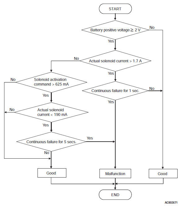
DTC SET CONDITIONS
Check Conditions <Circuit continuity ground>
- Voltage of battery: 2 volts or more.
Judgment Criteria <Circuit continuity ground>
- Line pressure linear solenoid valve actual current: more than 1.7 A (1 second)
Check Conditions <Circuit continuity open>
- Voltage of battery: 2 volts or more.
- Line pressure linear solenoid valve activation command: more than 625 mA
Judgment Criteria <Circuit continuity open>
- Line pressure linear solenoid valve actual current: less than 190 mA. (5 seconds)
OBD-II DRIVE CYCLE PATTERN
Start the engine, and maintain the status for approximately 10 seconds. Then, turn the ignition switch from OFF to ON, restart the engine, and then maintain the status for approximately 10 seconds.
TROUBLESHOOTING HINTS (THE MOST LIKELY CAUSES FOR THIS CODE TO BE SET ARE:)
- Malfunction of the line pressure linear solenoid valve system circuit
- Damaged harness or connector
- Malfunction of the TCM
- Malfunction of the line pressure linear solenoid valve (valve body assembly)
DIAGNOSIS
STEP 1. Check the TCM terminal voltage.
[C-37 TCM connector (vehicle side, connected) ]
Measure the voltage between the terminal No. 40 and body ground.
- While driving: 300 Hz
- Other than above: 0 V
Q: Is the check result normal?
YES : Go to Step 5.
NO : Go to Step 2.
STEP 2. Check between the TCM connector and A/T control solenoid valve assembly connector.
Check for continuity between C-37 TCM connector and B-111 A/T control solenoid valve assembly connector.
NOTE: Prior to the wiring harness inspection, check the intermediate connectors A-12 and repair that if necessary.
- Between C-37 terminal No. 40 and B-111 terminal No. 9: Continuity exists.
When the continuity check result is OK, check that the wiring harness is not shorted to the body and other wiring harness.
Q: Is the check result normal?
YES : Go to Step 3.
NO : Repair or replace the failure section.
STEP 3. Check the line pressure linear solenoid.
Q: Is the check result normal?
YES : Go to Step 6.
NO : Go to Step 4.
STEP 4. Check between the A/T control solenoid valve assembly connector and the line pressure linear solenoid valve connector.
Check for continuity between the A/T control solenoid valve assembly connector terminals and the line pressure linear solenoid valve connector terminals.
- Between C-111 terminal No. 9 and line pressure linear solenoid valve: Continuity exists.
Q: Is the check result satisfactory?
YES : Replace the valve body assembly.
NO : Repair or replace the failure section.
STEP 5. Check the TCM and A/T control solenoid valve assembly connector pin terminals and the connection status.
Q: Is the check result normal?
YES : Go to Step 7.
NO : Repair or replace the failure section.
STEP 6. Check the TCM and A/T control solenoid valve assembly connector pin terminals and the connection status.
Q: Is the check result normal?
YES : Replace the TCM.
NO : Repair or replace the failure section.
STEP 7. Erase the DTC code, and drive the vehicle for a while.
Check that the normal code is displayed.
Q: Is the check result normal?
YES : The procedure is complete.
NO : Return to START.
DTC P0753: Low Clutch Linear Solenoid Valve System
DESCRIPTIONS OF MONITOR METHODS
1st to 4th gear driving
- Open or short circuit is detected for 5 seconds.
- The control current of solenoid valve is abnormally large or small.
MONITOR EXECUTION
- 1st to 4th gear driving
MONITOR EXECUTION CONDITIONS (OTHER MONITOR AND SENSOR)
Other Monitor (There is no temporary DTC stored in memory for the item monitored below)
- P0731: Malfunction of the 1st gear incorrect ratio
- P0732: Malfunction of the 2nd gear incorrect ratio
- P0733: Malfunction of the 3rd gear incorrect ratio
- P0734: Malfunction of the 4th gear incorrect ratio
- P0735: Malfunction of the 5th gear incorrect ratio
- P0729: Malfunction of the 6th gear incorrect ratio
Sensor (The sensor below is determined to be normal)
- Not applicable
LOGIC FLOW CHARTS (Monitor Sequence)
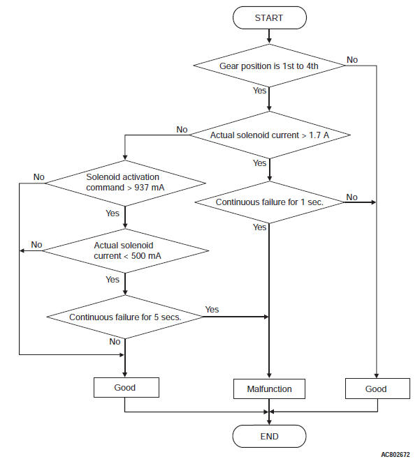
DTC SET CONDITIONS
Check Conditions <Circuit continuity ground>
- Gear position: 1st to 4th.
Judgment Criteria <Circuit continuity ground>
- Low clutch linear solenoid valve actual current: more than 1.7 A (1 second)
Check Conditions <Circuit continuity open>
- Gear position: 1st to 4th.
- Low clutch linear solenoid valve activation command: more than 937 mA
Judgment Criteria <Circuit continuity open>
- Low clutch linear solenoid valve actual current: less than 500 mA. (5 seconds)
OBD-II DRIVE CYCLE PATTERN
Drive in 1st to 4th gears. Maintain each shift range for approximately 10 seconds.
TROUBLESHOOTING HINTS (THE MOST LIKELY CAUSES FOR THIS CODE TO BE SET ARE:)
- Malfunction of the low clutch linear solenoid valve system circuit
- Damaged harness or connector
- Malfunction of the TCM
- Malfunction of the low clutch linear solenoid valve (valve body assembly)
DIAGNOSIS
STEP 1. Check the TCM terminal voltage.
[C-37 TCM connector (vehicle side, connected) ]
Measure the voltage between the terminal No. 41 and body ground.
- Low clutch engaged: 300 Hz
- Other than above: 0 V
Q: Is the check result normal?
YES : Go to Step 5.
NO : Go to Step 2.
STEP 2. Check between the TCM connector and A/T control solenoid valve assembly connector.
Check for continuity between C-37 TCM connector and B-111 A/T control solenoid valve assembly connector.
NOTE: Prior to the wiring harness inspection, check the intermediate connectors A-12 and repair that if necessary.
- Between C-37 terminal No. 41 and B-111 terminal No. 1: Continuity exists.
When the continuity check result is OK, check that the wiring harness is not shorted to the body and other wiring harness.
Q: Is the check result normal?
YES : Go to Step 3.
NO : Repair or replace the failure section.
STEP 3. Check the low clutch linear solenoid.
Q: Is the check result normal?
YES : Go to Step 6.
NO : Go to Step 4.
STEP 4. Check between the A/T control solenoid valve assembly connector and the low clutch linear solenoid valve connector.
Check for continuity between the A/T control solenoid valve assembly connector terminals and the low clutch linear solenoid valve connector terminals.
- Between C-111 terminal No. 1 and low clutch linear solenoid valve: Continuity exists.
Q: Is the check result satisfactory? YES : Replace the valve body assembly.
NO : Repair or replace the failure section.
STEP 5. Check the TCM and A/T control solenoid valve assembly connector pin terminals and the connection status.
Q: Is the check result normal?
YES : Go to Step 7.
NO : Repair or replace the failure section.
STEP 6. Check the TCM and A/T control solenoid valve assembly connector pin terminals and the connection status.
Q: Is the check result normal?
YES : Replace the TCM.
NO : Repair or replace the failure section.
STEP 7. Erase the DTC code, and drive the vehicle for a while.
Check that the normal code is displayed.
Q: Is the check result normal?
YES : The procedure is complete.
NO : Return to START.
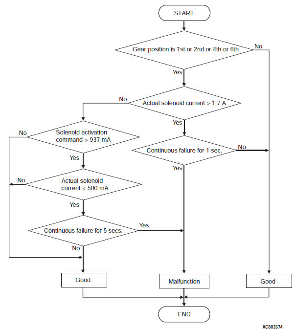
DTC P0758: 2-6 Brake Linear Solenoid Valve System
DESCRIPTIONS OF MONITOR METHODS
2nd or 6th gear driving
- Open or short circuit is detected for 5 seconds.
- The control current of solenoid valve is abnormally large or small.
MONITOR EXECUTION
- 2nd or 6th gear driving
MONITOR EXECUTION CONDITIONS (OTHER MONITOR AND SENSOR)
Other Monitor (There is no temporary DTC stored in memory for the item monitored below)
- P0731: Malfunction of the 1st gear incorrect ratio
- P0732: Malfunction of the 2nd gear incorrect ratio
- P0733: Malfunction of the 3rd gear incorrect ratio
- P0734: Malfunction of the 4th gear incorrect ratio
- P0735: Malfunction of the 5th gear incorrect ratio
- P0729: Malfunction of the 6th gear incorrect ratio
- P0846: Malfunction of the 2-6 brake pressure switch system
Sensor (The sensor below is determined to be normal)
- Not applicable
LOGIC FLOW CHARTS (Monitor Sequence)
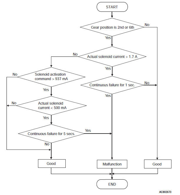
DTC SET CONDITIONS
Check Conditions <Circuit continuity ground>
- Gear position: 2nd or 6th.
Judgment Criteria <Circuit continuity ground>
- 2-6 brake linear solenoid valve actual current: more than 1.7 A (1 second)
Check Conditions <Circuit continuity open>
- Gear position: 2nd or 6th.
- 2-6 brake linear solenoid valve activation command: more than 937 mA
Judgment Criteria <Circuit continuity open>
- 2-6 brake linear solenoid valve actual current: less than 500 mA. (5 seconds)
OBD-II DRIVE CYCLE PATTERN
Drive in 2nd or 6th gear. Maintain each shift range for 10 second or more.
TROUBLESHOOTING HINTS (THE MOST LIKELY CAUSES FOR THIS CODE TO BE SET ARE:)
- Malfunction of the 2-6 brake linear solenoid valve system circuit
- Damaged harness or connector
- Malfunction of the TCM
- Malfunction of the 2-6 brake linear solenoid valve (valve body assembly)
DIAGNOSIS
STEP 1. Check the TCM terminal voltage.
[C-38 TCM connector (vehicle side, connected) ]
Measure the voltage between the terminal No. 3 and body ground.
- 2-6 brake engaged (2nd and 6th gear): 300 Hz
- Other than above: 0 V
Q: Is the check result normal?
YES : Go to Step 5.
NO : Go to Step 2.
STEP 2. Check between the TCM connector and A/T control solenoid valve assembly connector.
Check for continuity between C-38 TCM connector and B-111 A/T control solenoid valve assembly connector.
NOTE: Prior to the wiring harness inspection, check the intermediate connectors A-12 and repair that if necessary.
- Between C-38 terminal No. 3 and B-111 terminal No. 6: Continuity exists.
When the continuity check result is OK, check that the wiring harness is not shorted to the body and other wiring harness.
Q: Is the check result normal?
YES : Go to Step 3.
NO : Repair or replace the failure section.
STEP 3. Check the 2-6 brake linear solenoid.
Q: Is the check result normal?
YES : Go to Step 6.
NO : Go to Step 4.
STEP 4. Check between the A/T control solenoid valve assembly connector and the 2-6 brake linear solenoid valve connector.
Check for continuity between the A/T control solenoid valve assembly connector terminals and the 2-6 brake linear solenoid valve connector terminals.
- Between C-111 terminal No. 6 and the 2-6 brake linear solenoid valve: Continuity exists.
Q: Is the check result satisfactory? YES : Replace the valve body assembly.
NO : Repair or replace the failure section.
STEP 5. Check the TCM and A/T control solenoid valve assembly connector pin terminals and the connection status.
Q: Is the check result normal?
YES : Go to Step 7.
NO : Repair or replace the failure section.
STEP 6. Check the TCM and A/T control solenoid valve assembly connector pin terminals and the connection status.
Q: Is the check result normal?
YES : Replace the TCM.
NO : Repair or replace the failure section.
STEP 7. Erase the DTC code, and drive the vehicle for a while.
Check that the normal code is displayed.
Q: Is the check result normal?
YES : The procedure is complete.
NO : Return to START.
DTC P0763: 3-5 Reverse Clutch Linear Solenoid Valve System
DESCRIPTIONS OF MONITOR METHODS
1st, 2nd, 4th, or 6th gear driving
- Open or short circuit is detected for 5 seconds.
- The control current of solenoid valve is abnormally large or small.
MONITOR EXECUTION
- 1st, 2nd, 4th, and 6th gear driving
MONITOR EXECUTION CONDITIONS (OTHER MONITOR AND SENSOR)
Other Monitor (There is no temporary DTC stored in memory for the item monitored below)
- P0731: Malfunction of the 1st gear incorrect ratio
- P0732: Malfunction of the 2nd gear incorrect ratio
- P0733: Malfunction of the 3rd gear incorrect ratio
- P0734: Malfunction of the 4th gear incorrect ratio
- P0735: Malfunction of the 5th gear incorrect ratio
- P0729: Malfunction of the 6th gear incorrect ratio
Sensor (The sensor below is determined to be normal)
- Not applicable
LOGIC FLOW CHARTS (Monitor Sequence)
DTC SET CONDITIONS
Check Conditions <Circuit continuity ground>
- Gear position: 1st or 2nd or 4th or 6th.
Judgment Criteria <Circuit continuity ground>
- 3-5 reverse clutch linear solenoid valve actual current: more than 1.7 A (1 second)
Check Conditions <Circuit continuity open>
- Gear position: 1st or 2nd or 4th or 6th.
- 3-5 reverse clutch linear solenoid valve activation command: more than 937 mA
Judgment Criteria <Circuit continuity open>
- 3-5 reverse clutch linear solenoid valve actual current: less than 500 mA. (5 seconds)
OBD-II DRIVE CYCLE PATTERN
Drive in 1st, 2nd, 4th, and 6th gears. Maintain each shift range for 10 second or more.
TROUBLESHOOTING HINTS (THE MOST LIKELY CAUSES FOR THIS CODE TO BE SET ARE:)
- Malfunction of the 3-5 reverse clutch linear solenoid valve system circuit
- Damaged harness or connector
- Malfunction of the TCM
- Malfunction of the 3-5 reverse clutch linear solenoid valve (valve body assembly)
DIAGNOSIS
STEP 1. Check the TCM terminal voltage.
[C-38 TCM connector (vehicle side, connected) ]
Measure the voltage between terminal No. 2 and body ground.
- When 3-5 reverse clutch engaged. (3rd, 5th, and reverse): 0 V
- Other than above: 300 Hz
Q: Is the check result normal?
YES : Go to Step 5.
NO : Go to Step 2.
STEP 2. Check between the TCM connector and A/T control solenoid valve assembly connector.
Check for continuity between C-38 TCM connector and B-111 A/T control solenoid valve assembly connector.
NOTE: Prior to the wiring harness inspection, check the intermediate connectors A-12 and repair that if necessary.
- Between C-38 terminal No. 2 and B-111 terminal No. 14: Continuity exists.
When the continuity check result is OK, check that the wiring harness is not shorted to the body and other wiring harness.
Q: Is the check result normal?
YES : Go to Step 3.
NO : Repair or replace the failure section.
STEP 3. Check the 3-5 reverse clutch linear solenoid.
Q: Is the check result normal?
YES : Go to Step 6.
NO : Go to Step 4.
STEP 4. Check between the A/T control solenoid valve assembly connector and 3-5 reverse clutch linear solenoid valve connector.
Check for continuity between the A/T control solenoid valve assembly connector terminals and 3-5 reverse clutch linear solenoid valve connector terminals.
- Between C-111 terminal No. 14 and the 3-5 reverse clutch linear solenoid valve: Continuity exists.
Q: Is the check result satisfactory?
YES : Replace the valve body assembly.
NO : Repair or replace the failure section.
STEP 5. Check the TCM and A/T control solenoid valve assembly connector pin terminals and the connection status.
Q: Is the check result normal?
YES : Go to Step 7.
NO : Repair or replace the failure section.
STEP 6. Check the TCM and A/T control solenoid valve assembly connector pin terminals and the connection status.
Q: Is the check result normal?
YES : Replace the TCM.
NO : Repair or replace the failure section.
STEP 7. Erase the DTC code, and drive the vehicle for a while.
Check that the normal code is displayed.
Q: Is the check result normal?
YES : The procedure is complete.
NO : Return to START.
DTC P0768: High Clutch Linear Solenoid Valve System
DESCRIPTIONS OF MONITOR METHODS
1st to 3rd gear driving
- Open or short circuit is detected for 5 seconds.
- The control current of solenoid valve is abnormally large or small.
MONITOR EXECUTION
- 1st, 2nd, and 3rd gear driving
MONITOR EXECUTION CONDITIONS (OTHER MONITOR AND SENSOR)
Other Monitor (There is no temporary DTC stored in memory for the item monitored below)
- P0731: Malfunction of the 1st gear incorrect ratio
- P0732: Malfunction of the 2nd gear incorrect ratio
- P0733: Malfunction of the 3rd gear incorrect ratio
- P0734: Malfunction of the 4th gear incorrect ratio
- P0735: Malfunction of the 5th gear incorrect ratio
- P0729: Malfunction of the 6th gear incorrect ratio
- P0876: Malfunction of the High clutch pressure switch system
Sensor (The sensor below is determined to be normal)
- Not applicable
LOGIC FLOW CHARTS (Monitor Sequence)
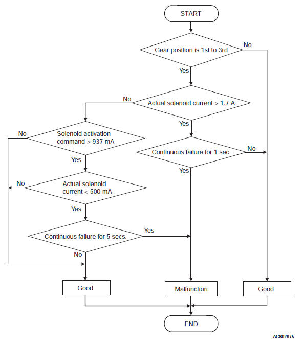
DTC SET CONDITIONS
Check Conditions <Circuit continuity ground>
- Gear position: 1st to 3rd.
Judgment Criteria <Circuit continuity ground>
- High clutch linear solenoid valve actual current: more than 1.7 A (1 second)
Check Conditions <Circuit continuity open>
- Gear position: 1st to 3rd.
- High clutch linear solenoid valve activation command: more than 937 mA
Judgment Criteria <Circuit continuity open>
- High clutch linear solenoid valve actual current: less than 500 mA. (5 seconds)
OBD-II DRIVE CYCLE PATTERN
Drive in 1st, 2nd, and 3rd gears. Maintain each shift range for 10 second or more.
TROUBLESHOOTING HINTS (THE MOST LIKELY CAUSES FOR THIS CODE TO BE SET ARE:)
- Malfunction of the high clutch linear solenoid valve system circuit
- Damaged harness or connector
- Malfunction of the TCM
- Malfunction of the high clutch linear solenoid valve (valve body assembly)
DIAGNOSIS
STEP 1. Check the TCM terminal voltage.
[C-38 TCM connector (vehicle side, connected) ]
Measure the voltage between the terminal No. 1 and body ground.
- High clutch engaged: 0 V
- Other than above: 300 Hz
Q: Is the check result normal?
YES : Go to Step 5.
NO : Go to Step 2.
STEP 2. Check between the TCM connector and A/T control solenoid valve assembly connector.
Check for continuity between C-38 TCM connector and B-111 A/T control solenoid valve assembly connector.
NOTE: Prior to the wiring harness inspection, check the intermediate connectors A-12 and repair that if necessary.
- Between C-38 terminal No. 1 and B-111 terminal No. 19: Continuity exists.
When the continuity check result is OK, check that the wiring harness is not shorted to the body and other wiring harness.
Q: Is the check result normal?
YES : Go to Step 3.
NO : Repair or replace the failure section.
STEP 3. Check the high clutch linear solenoid.
Q: Is the check result normal?
YES : Go to Step 6.
NO : Go to Step 4.
STEP 4. Check between the A/T control solenoid valve assembly connector and the high clutch linear solenoid valve connector.
Check for continuity between the A/T control solenoid valve assembly connector terminals and the high clutch linear solenoid valve connector terminals.
- Between C-111 terminal No. 19 and high clutch linear solenoid valve: Continuity exists.
Q: Is the check result satisfactory? YES : Replace the valve body assembly.
NO : Repair or replace the failure section.
STEP 5. Check the TCM and A/T control solenoid valve assembly connector pin terminals and the connection status.
Q: Is the check result normal?
YES : Go to Step 7.
NO : Repair or replace the failure section.
STEP 6. Check the TCM and A/T control solenoid valve assembly connector pin terminals and the connection status.
Q: Is the check result normal?
YES : Replace the TCM.
NO : Repair or replace the failure section.
STEP 7. Erase the DTC code, and drive the vehicle for a while.
Check that the normal code is displayed.
Q: Is the check result normal?
YES : The procedure is complete.
NO : Return to START.
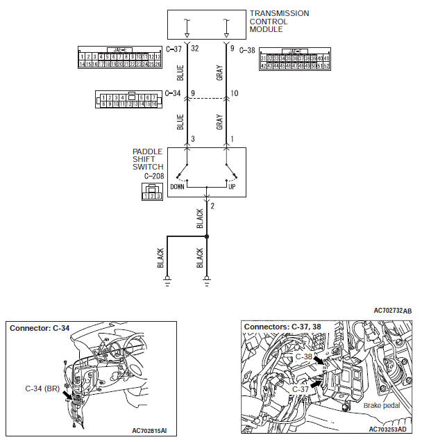
DTC P0815: Paddle Shift Switch (Up) System
Paddle shift switch system circuit
DESCRIPTIONS OF MONITOR METHODS
- With the ignition switch ON, the paddle shift switch (up) status continues for 60 seconds.
TROUBLESHOOTING HINTS (THE MOST LIKELY CAUSES FOR THIS CODE TO BE SET ARE:)
- Malfunction of the Paddle shift switch (up) system circuit
- Damaged harness or connector
- Malfunction of the TCM
- Malfunction of the paddle shift switch
DIAGNOSIS
STEP 1. Check the TCM terminal voltage.
[C-38 TCM connector (vehicle side, connected) ]
- Measure the voltage between C-38 No. 9 and body ground.
- Ignition switch: ON
- Paddle (ON) operated: 1V or less
- Other than above: battery positive voltage
Q: Is the check result normal?
YES : Go to Step 2.
NO : Go to Step 3.
STEP 2. Check the TCM connector, vehicle-side wiring harness connector pin terminal, and the connection status.
Q: Is the check result normal?
YES : Go to Step 6.
NO : Repair or replace the failure section.
STEP 3. Check between the TCM connector and the paddle shift switch (up).
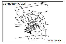
Check for continuity between C-38 TCM connector terminal No.
9 and C-208 paddle shift switch (up).
NOTE: Prior to the wiring harness inspection, check the intermediate connectors C-34 and repair that if necessary.
- Between C-38 terminal No. 9 and C-208 terminal No. 1: Continuity exists.
When the continuity check result is OK, check that the wiring harness is not shorted to the body and other wiring harness.
Q: Is the check result normal?
YES : Go to Step 4.
NO : Repair or replace the failure section.
STEP 4. Check the paddle shift switch (up).
Q: Is the check result normal?
YES : Go to Step 5.
NO : Repair or replace the failure section.
STEP 5. Check the TCM connector, vehicle-side wiring harness connector pin terminal, and the connection status.
Q: Is the check result normal?
YES : Replace the TCM.
NO : Repair or replace the failure section.
STEP 6. Erase the DTC code, and drive the vehicle for a while.
Check that the normal code is displayed.
Q: Is the check result normal?
YES : The procedure is complete.
NO : Return to START.
DTC P0816: Paddle Shift Switch (Down) System
DESCRIPTIONS OF MONITOR METHODS
- With the ignition switch ON, the paddle shift switch (down) status continues for 60 seconds.
TROUBLESHOOTING HINTS (THE MOST LIKELY CAUSES FOR THIS CODE TO BE SET ARE:)
- Malfunction of the Paddle shift switch (down) system circuit
- Damaged harness or connector
- Malfunction of the TCM
- Malfunction of the paddle shift switch
DIAGNOSIS
STEP 1. Check the TCM terminal voltage.
[C-37 TCM connector (vehicle side, connected) ]
Measure the voltage between C-37 terminal No. 32 and body ground.
- Ignition switch: ON
- Paddle (ON) operated: 1V or less
- Other than above: battery positive voltage
Q: Is the check result normal?
YES : Go to Step 2.
NO : Go to Step 3.
STEP 2. Check the TCM connector, vehicle-side wiring harness connector pin terminal, and the connection status.
Q: Is the check result normal?
YES : Go to Step 6.
NO : Repair or replace the failure section.
STEP 3. Check between the TCM connector and the paddle shift switch (down).
Check for continuity between C-37 TCM connector and C-208 paddle shift switch (down).
NOTE: Prior to the wiring harness inspection, check the intermediate connectors C-34 and repair that if necessary.
- Between C-37 terminal No. 32 and C-208 terminal No. 3: Continuity exists.
When the continuity check result is OK, check that the wiring harness is not shorted to the body and other wiring harness.
Q: Is the check result normal?
YES : Go to Step 4.
NO : Repair or replace the failure section.
STEP 4. Check the paddle shift switch (down).
Q: Is the check result normal?
YES : Go to Step 5.
NO : Repair or replace the failure section.
STEP 5. Check the TCM connector, vehicle-side wiring harness connector pin terminal, and the connection status.
Q: Is the check result normal?
YES : Replace the TCM.
NO : Repair or replace the failure section.
STEP 6. Erase the DTC code, and drive the vehicle for a while.
Check that the normal code is displayed.
Q: Is the check result normal?
YES : The procedure is complete.
NO : Return to START.
DTC P0826: Shift Switch Assembly System
Shift switch assembly system circuit
DESCRIPTIONS OF MONITOR METHODS
- With the ignition switch ON, an abnormal signal combination is detected for 2 seconds.
TROUBLESHOOTING HINTS (THE MOST LIKELY CAUSES FOR THIS CODE TO BE SET ARE:)
- Malfunction of the shift switch assembly system circuit
- Damaged harness or connector
- Malfunction of the TCM
- Malfunction of the select switch
- Malfunction of the Shift switch (up)
- Malfunction of the Shift switch (down)
DIAGNOSIS
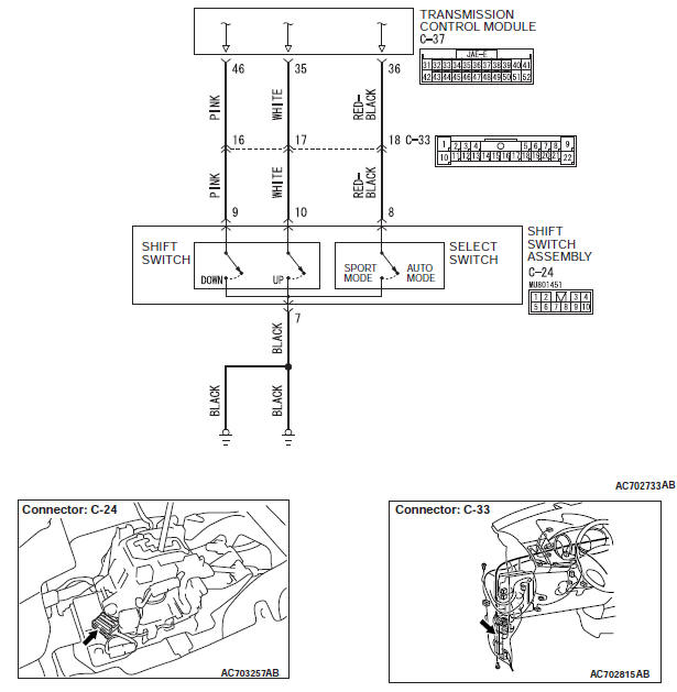
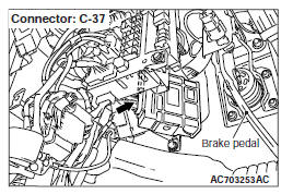
STEP 1. Check the TCM terminal voltage.
[C-37 TCM connector (vehicle side, connected) ]
Measure the voltage between the TCM connector terminals and body ground.
- Ignition switch: ON
- Between C-37 terminal No. 36 and body ground
Sport mode selected: 1 V or less
Other than above: battery positive voltage - Between C-37 terminal No. 35 and body ground
Shift switch (up) operated: 1V or less
Other than above: battery positive voltage - Between C-37 terminal No. 46 and body ground
Shift switch (down) operated: 1 V or less
Other than above: battery positive voltage
Q: Is the check result normal?
YES : Go to Step 2.
NO : Go to Step 3.
STEP 2. Check the TCM connector, vehicle-side wiring harness connector pin terminal, and the connection status.
Q: Is the check result normal?
YES : Go to Step 9.
NO : Repair or replace the failure section.
STEP 3. Check between the TCM connector and the select switch.
Check for continuity between the C-37 TCM connector and the C-24 select switch.
NOTE: Prior to the wiring harness inspection, check the intermediate connectors C-33 and repair that if necessary.
- Between C-37 terminal No. 36 and C-24 terminal No. 8: Continuity exists.
When the continuity check result is OK, check that the wiring harness is not shorted to the body and other wiring harness.
Q: Is the check result normal?
YES : Go to Step 4.
NO : Repair or replace the failure section.
STEP 4. Check between the shift switch assembly and body ground.
Check for continuity between the C-24 shift switch assembly (ground) and body ground.
- Between C-24 terminal No. 7 and body ground: Continuity exists.
Q: Is the check result normal?
YES : Go to Step 5.
NO : Repair or replace the failure section.
STEP 5. Check between the TCM connector and the shift switch (up).
Check for continuity between the C-37 TCM connector and the shift switch (up).
- Between C-37 terminal No. 35 and C-24 terminal No. 10: Continuity exists.
When the continuity check result is OK, check that the wiring harness is not shorted to the body and other wiring harness.
Q: Is the check result normal?
YES : Go to Step 6.
NO : Repair or replace the failure section.
STEP 6. Check between the TCM connector and the shift switch (down).
Check for continuity between the C-37 TCM connector and the shift switch (down).
- Between C-37 terminal No. 46 and C-24 terminal No. 9: Continuity exists.
When the continuity check result is OK, check that the wiring harness is not shorted to the body and other wiring harness.
Q: Is the check result normal?
YES : Go to Step 7.
NO : Repair or replace the failure section.
STEP 7. Check the shift switch assembly as a single unit.
Q: Is the check result normal?
YES : Go to Step 8.
NO : Repair or replace the failure section.
STEP 8. Check the TCM, vehicle-side wiring harness connector pin terminal, and the connection status.
Q: Is the check result normal?
YES : Replace the TCM.
NO : Repair or replace the failure section.
STEP 9. Erase the DTC code, and drive the vehicle for a while.
Check that the normal code is displayed.
Q: Is the check result normal?
YES : The procedure is complete.
NO : Return to START.
DTC P0846: 2-6 Brake Pressure Switch System
Pressure switch system circuit
DESCRIPTIONS OF MONITOR METHODS
- With the solenoid failure not detected and during 2nd or 6th gear driving, the switch OFF status continues for 2 seconds. (The detection is achieved twice during 1 driving cycle*1, and it continues for 2 driving cycles.)
*1: Indicates the series of driving cycle "ignition key OFF → ON → drive → OFF". The "1 driving cycle", "2 driving cycle", and so on indicates how many cycles are required to detect a failure.
MONITOR EXECUTION
- 2nd or 6th gear driving
MONITOR EXECUTION CONDITIONS (OTHER MONITOR AND SENSOR)
Other Monitor (There is no temporary DTC stored in memory for the item monitored below)
- Not applicable
Sensor (The sensor below is determined to be normal)
- Not applicable
LOGIC FLOW CHARTS (Monitor Sequence)
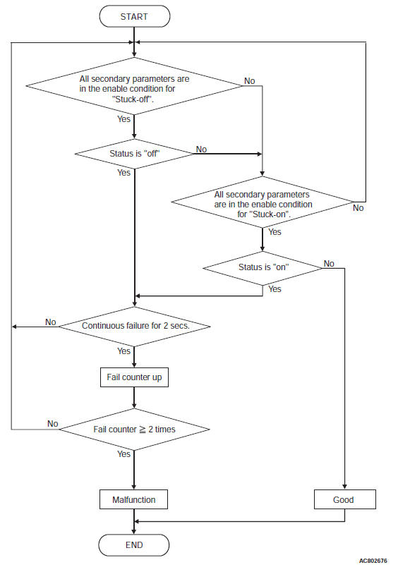
DTC SET CONDITIONS
Check Conditions <Stuck-off>
- Transmission range switch position: D
- Gear position: 2nd, 6th
- Time after shift changing finish: 2 seconds or more
Judgment Criteria <Stuck-off>
- 2-6 brake pressure switch status: OFF (2 seconds × 2times)
Check Conditions <Stuck-on>
- Transmission range switch position: D or R
- Gear position: 1st, 3rd, 4th, 5th, reverse
- Time after shift changing finish: 2 seconds or more
Judgment Criteria <Stuck-on>
- 2-6 brake pressure switch status: ON (2 seconds × 2times)
OBD-II DRIVE CYCLE PATTERN
Drive in 2nd and 6th gears for 2 seconds or more.
TROUBLESHOOTING HINTS (THE MOST LIKELY CAUSES FOR THIS CODE TO BE SET ARE:)
- Malfunction of the 2-6 brake pressure switch system circuit
- Damaged harness or connector
- Malfunction of the TCM
- Malfunction of the 2-6 brake pressure switch (valve body assembly)
- Malfunction of the valve body assembly, abnormal hydraulic circuit valve.
CAUTION For the incomplete gear shifting and slippage, first refer to the SYMPTOM CHART.
DIAGNOSIS
STEP 1. Check the DTC.
Q: Is the DTC other than the pressure switch set? (Is the code other than P0846, P0876, and P0988 set?)
YES : Check and repair the relevant DTC system.
NO : Go to Step 2.
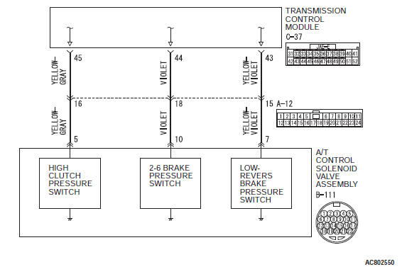
STEP 2. Check the TCM terminal voltage.
[C-37 TCM connector (vehicle side, connected) ]
Measure the voltage between C-37 terminal No. 44 and body ground.
- 2-6 brake engaged: 0 V
- Other than above: Battery positive voltage
Q: Is the check result normal?
YES : Go to Step 3.
NO : Go to Step 7.
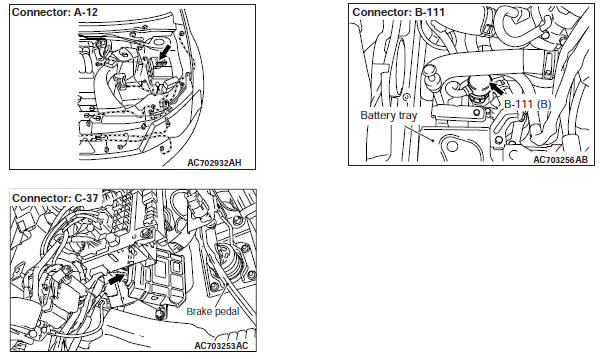
STEP 3. Check between the TCM connector and A/T control solenoid valve assembly.
Check for continuity between C-37 TCM connector and B-111 A/T control solenoid valve assembly connector.
NOTE: Prior to the wiring harness inspection, check the intermediate connectors A-12 and repair that if necessary.
- Between C-37 terminal No. 44 and B-111 terminal No. 10: Continuity exists.
When the continuity check result is OK, check that the wiring harness is not shorted to the body and other wiring harness.
Q: Is the check result normal?
YES : Go to Step 4.
NO : Repair or replace the failure section.
STEP 4. Check the TCM, A/T control solenoid valve assembly connector pin terminals, and the connection status.
Q: Is the check result normal?
YES : Go to Step 5.
NO : Repair or replace the failure section.
STEP 5. Check between the A/T control solenoid valve assembly connector and 2-6 brake pressure switch connector.
Check for continuity between the B-111 A/T control solenoid valve assembly connector terminals and 2-6 brake pressure switch connector terminals.
- Between B-111 terminal No. 10 and 2-6 brake pressure switch: Continuity exists.
When the continuity check result is OK, check that the wiring harness is not shorted to the body and other wiring harness.
Q: Is the check result normal?
YES : Go to Step 6.
NO : Repair or replace the failure section.
STEP 6. Check the 2-6 brake pressure switch body ground.
Check for continuity between the 2-6 brake pressure switch body and ground.
- Between the 2-6 brake pressure switch body and body ground: Continuity exists.
Q: Is the check result normal?
YES : Replace the valve body assembly, and then go to Step 8.
NO : Repair or replace the failure section.
STEP 7. Check the TCM, A/T control solenoid valve assembly connector pin terminals, and the connection status.
Q: Is the check result normal?
YES : Go to Step 9.
NO : Repair or replace the failure section.
STEP 8. Erase the DTC code, and drive the vehicle for a while.
Check that the normal code is displayed.
Q: Is the check result normal?
YES : The procedure is complete.
NO : Replace the TCM.
STEP 9. Erase the DTC code, and drive the vehicle for a while.
Check that the normal code is displayed.
Q: Is the check result normal?
YES : The procedure is complete.
NO : Return to START.
READ NEXT:
 DTC P0876, P0893, P0988, P1705, P1706, P1731, P1753, P1758, P1773,
P1796, U0001, U0100, U0121, U0141
DTC P0876, P0893, P0988, P1705, P1706, P1731, P1753, P1758, P1773,
P1796, U0001, U0100, U0121, U0141
DTC P0876: High Clutch Pressure Switch System
DESCRIPTIONS OF MONITOR METHODS
With the solenoid failure not detected and with
4th to 6th gear driving, the switch OFF status
continues for 2 seconds
Inspection Procedure
INSPECTION PROCEDURE 1: The vehicle does not run at any range
(including low power).
TROUBLESHOOTING HINTS (THE MOST
LIKELY CAUSES FOR THIS CONDITION:)
Malfunction of the engine
Insufficient trans
Diagnosis S-AWC (Super All Wheel Control)
TROUBLESHOOTING STRATEGY
Refer to GROUP 00 − How to Use Troubleshooting/
Inspection Service Points.
PRECAUTIONS FOR DIAGNOSIS
Before diagnosis, check that all the following items
are normal.
SEE MORE:
Power Steering Oil Pump
Assembly
REMOVAL AND INSTALLATION
Pre-removal operation
Power Steering Fluid Draining
Engine Upper Cover Removal
Engine Room Side Cover (RH) Removal
Generator and Others Belt Removal
Post-installation operation
Generator and Others Belt Installation
Generator and Others Belt Tension Check
Engin
Specifications, General Information, Service Precautions
Fastener Tightening Specifications
General Information
DANGER
The SRS-ECU adopts the rollover specification
that the curtain airbag and seat belt
pre-tensioner operate at the occurrence of
rollover. Therefore, do not tilt the vehicle to
the right and left with the IG ON or tilt the
SRS-ECU to the r
