Mitsubishi Outlander: Automatic Transaxle Diagnosis (A/T)
DIAGNOSTIC TROUBLESHOOTING FLOW
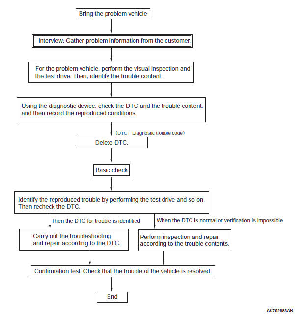
INTRODUCTION TO A/T DIAGNOSIS
When the A/T is failed, have an interview with the user to gather precise information on the failure status.
After that, perform on-board test to check if the failure is reproduced, and then start repair work. If the repair work is started on the assumption that the A/T is the failure cause from the beginning, the cause would not be investigated, and moreover, the secondary failure may be caused, resulting in a waste of repair time.
Failures regarding the A/T are categorized as follows.
1. Poor adjustment, poor installation between the engine and body, and malfunction due to non-genuine device installation
2. Poor engine performance
3. Malfunction of the electronic control device
4. Malfunction of the A/T inside (hydraulic control system, etc.)
5. Others (oil leakage, damage, etc.)
A/T DIAGNOSTIC TROUBLESHOOTING STRATEGY
Interview is the first step of the diagnosis. It requires a correct observation of the actual trouble symptom, and a proper judgment without preconceived idea. If the trouble symptom has occurred when the vehicle is brought, it is easy to check the fact. However, when the trouble has not occurred at that time, it is important to have an interview with the user to gather information about the reproduction conditions, and exert maximum effort to reproduce the trouble.
NOTE: These interviews should be listed up.
1. Does it occur when the engine is cold or after it is warmed up?
2. Does it occur on a specific road (slope, curve, long straight road, bumpy road, etc.)?
3. Does it occur with the vehicle speed in a specific range or at vehicle stop?
4. Does it occur during acceleration or deceleration?
5. Does it occur sometimes or consecutively?
6. Does it occur in the transmission range "P", "R", "N", or "D"?
7. Does it change in accordance with the vehicle speed or the engine speed?
8. Does it occur with a specific accelerator angle (e.g. half throttle)? Does it occur at the time of traffic jams?
9. Does it occur all of a sudden recently or has it been noticeable since the vehicle was delivered?
10.(Other) Does it occur after the vehicle experienced the following conditions?: Heavy load, rain, water passage or river, mountain road or rough road; Installation of car navigation, remote controlled starter, audio device, radio transmission equipment, theft prevention device, etc, Addition of battery fluid; Other vehicle troubles.
PRIMARY CHECK
Basic adjustment and maintenance of the A/T needs to be checked.
Check items
1. Check the power supply voltage, and check the voltage with the engine stopped. (If malfunction occurs, charge or replace that.)
2. Check the transmission fluid for abnormalities of level, smell, fouling, and color.
3. Check the transaxle control cable and linkage. (If dislocation occurs, adjust that.)
4. Check the connector connection, fouling, corrosion, and fixing status of the A/T-related electric wire.
5. Stall test (If the speed is below the specified value, check the engine side.)
6. Hydraulic pressure test
7. Engine idle speed, speed change occurrence (If a failure occurs, check the engine side.)
8. Check the presence of non-genuine devices (car navigation, remote controlled starter, audio device, radio transmission equipment, theft prevention device, aeroparts, etc.), the presence of power supply wiring and the additional signal wiring.
Then, remove improper power supply, signal wiring, and parts to check.
DIAGNOSIS FUNCTION
WARNING INDICATOR
When any malfunction occurs in the items related to the A/T system, which are described below, the symbol (A) continues being displayed in the information screen in the multi information display.
Check if the diagnostic trouble code is set when the symbol (A) continues being displayed in the information screen in the multi information display.
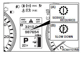
NOTE: When the symbol (B) is displayed in the information screen in the multi information display, the transmission fluid temperature is high. (Symbol (B) is turned on when the fluid temperature is approximately 140ºC (284ºF)or higher and turned off automatically when the fluid temperature drops below approximately 135ºC(275ºF).
NOTE: When transmission fluid becomes a high temperature, control to lower temperature of transmission fluid acts, and "D" is displayed of a run with sports mode by a shift indicator in a multi information display; and normal from sports mode; shifting is replaced automatically. In addition, there is the case that does not accept operation to sports mode. It is control to lower temperature of transmission fluid, and this phenomenon is not trouble. If temperature of transmission fluid falls, A/T returns to normal movement.
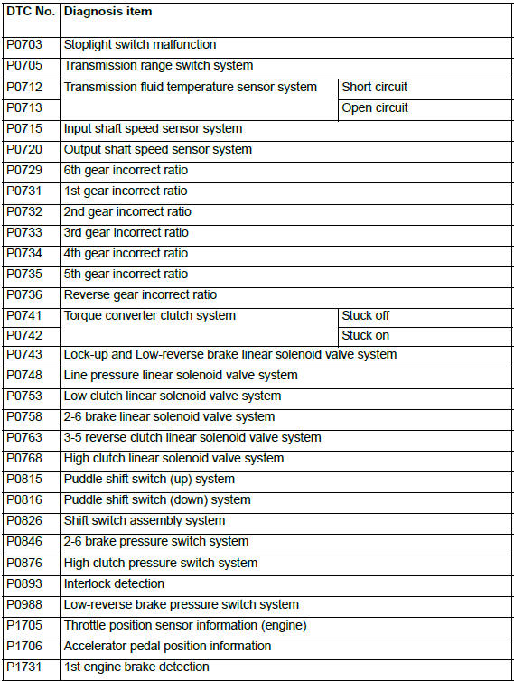
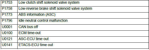
ON-BOARD DIAGNOSTICS
The transaxle control module (TCM) monitors its input/output signals (some signals all the time and others under specified conditions). When an irregular signal is initially monitored, the TCM decides that a malfunction has occurred and records the occurrence as a diagnostic trouble code. There are 39 diagnostic items. The diagnostic results can be read with scan tool. Diagnostic trouble codes are kept in memory by direct battery feed. The codes are retained in memory even if the ignition switch is in the "LOCK" (OFF) position. DTCs are not erased even after the battery terminals and the TCM connector are disconnected. In addition, the diagnostic trouble code can also be erased by scan tool.
NOTE: If a sensor is disconnected when the ignition switch is in the "ON" position, a diagnostic trouble code is stored in memory. In this case, erase the DTC using scan tool.
The 39 diagnostic items are displayed in numeric order.
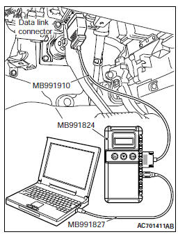
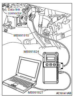
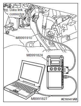
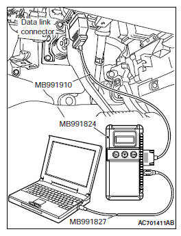
HOW TO CONNECT THE SCAN TOOL (M.U.T.-III)
Required Special Tools:
- MB991958: Scan Tool (M.U.T.-III Sub Assembly)
- MB991824: Vehicle Communication Interface (V.C.I.)
- MB991827: M.U.T.-III USB Cable
- MB991910: M.U.T.-III Main Harness A
CAUTION To prevent damage to scan tool MB991958, always turn the ignition switch to the "LOCK" (OFF) position before connecting or disconnecting scan tool MB991958.
1. Ensure that the ignition switch is at the "LOCK" (OFF) position.
2. Start up the personal computer.
3. Connect special tool MB991827 to special tool MB991824 and the personal computer.
4. Connect special tool MB991910 to special tool MB991824.
5. Connect special tool MB991910 to the data link connector.
6. Turn the power switch of special tool MB991824 to the "ON" position.
NOTE: When special tool MB991824 is energized, special tool MB991824 indicator light will be illuminated in a green color.
7. Start the M.U.T.-III system on the personal computer.
NOTE: Disconnecting scan tool MB991958 is the reverse of the connecting sequence, making sure that the ignition switch is at the "LOCK" (OFF) position.
HOW TO READ AND ERASE DIAGNOSTIC TROUBLE CODES
Required Special Tools:
- MB991958: Scan Tool (M.U.T.-III Sub Assembly)
- MB991824: V.C.I.
- MB991827: M.U.T.-III USB Cable
- MB991910: M.U.T.-III Main Harness A
CAUTION To prevent damage to scan tool MB991958, always turn the ignition switch to the "LOCK" (OFF) position before connecting or disconnecting scan tool MB991958.
NOTE: If the battery voltage is low, diagnostic trouble codes will not be set. Check the battery if scan tool MB991958 does not display.
1. Connect scan tool MB991958 to the data link connector.
2. Turn the ignition switch to the "ON" position.
3. Select "Interactive Diagnosis" from the start-up screen.
4. Select "System select".
5. Choose "ELC-A/T" from the "POWER TRAIN" tab.
6. Select "MITSUBISHI".
7. Select "Diagnostic Trouble Code".
8. If a DTC is set, it is shown.
9. Choose "Erase DTCs" to erase the DTC.
HOW TO READ DATA LIST
Required Special Tools:
- MB991958: Scan Tool (M.U.T.-III Sub Assembly)
- MB991824: V.C.I.
- MB991827: M.U.T.-III USB Cable
- MB991910: M.U.T.-III Main Harness A
CAUTION To prevent damage to scan tool MB991958, always turn the ignition switch to the "LOCK" (OFF) position before connecting or disconnecting scan tool MB991958.
1. Connect scan tool MB991958 to the data link connector.
2. Turn the ignition switch to the "ON" position.
3. Select "System select" from the start-up screen.
4. Select "From 2006 MY" of "Model Year". When the "Vehicle Information" is displayed, check the contents.
5. Select "ELC-A/T" from "System List", and press the "OK" button.
NOTE: When the "Loading Option Setup" list is displayed, check the applicable item.
6. Select "MITSUBISHI".
7. Select "Data List".
NOTE: When the "Data List Reference Table" button is selected, the service data reference table is displayed, and the normal values can be checked.
HOW TO DIAGNOSE THE CAN BUS LINES
Required Special Tools:
- MB991958: Scan Tool (M.U.T.-III Sub Assembly)
- MB991824: V.C.I.
- MB991827: M.U.T.-III USB Cable
- MB991910: M.U.T.-III Main Harness A
CAUTION To prevent damage to scan tool MB991958, always turn the ignition switch to the "LOCK" (OFF) position before connecting or disconnecting scan tool MB991958.
1. Connect scan tool MB991958 to the data link connector.
2. Turn the ignition switch to the "ON" position.
3. Select "CAN Bus Diagnosis" from the start-up screen.
4. When the vehicle information is displayed, confirm that it matches the vehicle whose CAN bus lines will be diagnosed.
- If they match, go to step 8.
- If not, go to step 5.
5. Select the "view vehicle information" button.
6. Enter the vehicle information and select the "OK" button.
7. When the vehicle information is displayed, confirm again that it matches the vehicle whose CAN bus lines will be diagnosed.
- If they match, go to step 8.
- If not, go to step 5.
8. Select the "OK" button.
9. When the optional equipment screen is displayed, choose the one which the vehicle is fitted with, and then select the "OK" button.
HOW TO INITIALIZE A/T LEARNED VALUE
PURPOSE
A/T learned value must be reset whenever the automatic transaxle, engine assembly, A/T valve body, or A/T solenoid valve is replaced. It cannot be reset by disconnecting the battery. Use the M.U.T.-III as follows:
INITIALIZATION PROCEDURE
1. Move the selector lever to the P range and turn the ignition switch to the LOCK (OFF) position.
Then, connect scan tool to the data link connector.
2. Turn the ignition switch to the ON position, and then move the selector lever to the R range.
3. Depress the accelerator pedal while depressing the brake pedal. (Engine is not running.)
Using the M.U.T.-III, execute the clear DTC function for the TCM (even if no codes are set).
NOTE: Performing initialization of the learned value will also erase the diagnostic trouble code.
FAIL-SAFE/BACKUP FUNCTION
When a malfunction of a main sensor or actuator is detected by the PCM, the transaxle is controlled by pre-set control logic to maintain safe conditions for driving.
The following table shows how the fail-safe/backup function affects vehicle driveability and operation.
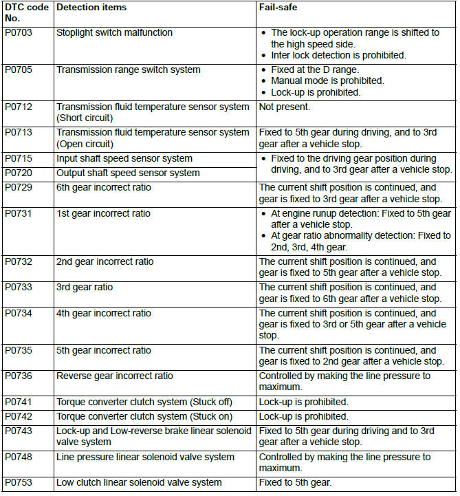
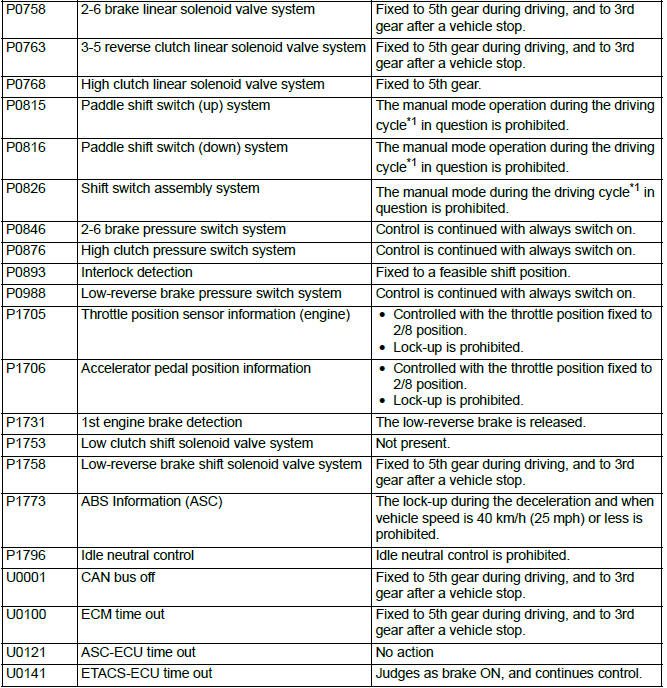
*1: Indicates the series of driving cycle "ignition key OFF → ON → drive → OFF".
ROAD TEST
This test is performed to make a proper judgment on the trouble symptom and check after completion of service work.
1. With the actual driving, check if there is any abnormality in transmission.
2. Check if there is any shift shock or abnormal sound.
3. Check the driving status with all the shift ranges including "R".
4. Perform the driving test with the reproduction condition which is investigated in the interview to check the failure occurrence.
P-range test
1. Stop the vehicle completely on an upslope at the gradient of 5º to 10º, and then shift the selector lever to the "P" range. After that, release the foot brake gradually to check that the vehicle does not move.
2. With the status of the above Step 1, shift the selector lever from the "P" range to other ranges, and check that the vehicle moves.
3. Check the operation also on the downslope with the same manner.
Select time lag
CAUTION
- Perform the test with the engine fully warmed up and the idling speed being stable.
- On completion of the first test, when one minute or more has elapsed after the selector lever is returned from another position to the "N" range, perform the following tests.
1. Check the transmission fluid level and properties.
2. Check the transaxle control cable and linkage.
3. Chock the front and rear wheels on a level surface, and depress the foot brake to stop the vehicle.
4. Start the engine, and shift the selector lever from the "N" range to the "D" range. At this time, measure the time from the lever selection to shock occurrence using a stop watch.
Standard value: − select time lag: 0.8 seconds
5. With the same manner, measure the select time from the "N" range to the "R" range.
Standard value: − select time lag: 0.8 seconds
If the measured value is abnormally large exceeding one second, the operating hydraulic pressure reduction and the A/T internal clutch slippage are assumed to have occurred.
TORQUE CONVERTER STALL TEST
This test measures the maximum engine speed when the selector lever is in the "D" position and the torque converter stalls. This tests the operation of the torque converter, stator and one-way clutch operation, as well as the holding performance of the clutches and brakes in the transaxle.
WARNING Do not let anyone stand in front of or behind the vehicle while this test is performed.
1. Check the transmission fluid level and temperature. Check the engine coolant temperature.
- Transmission fluid level: At the "HOT" mark on the dipstick
- Transmission fluid temperature: 70 − 80ºC (158 − 176ºF)
- Engine coolant temperature: 80 − 100ºC (176 − 212ºF)
NOTE: Measure transmission fluid temperature with scan tool MB991958 (M.U.T.-III sub assembly).
2. Chock both rear wheels.
3. Connect a tachometer.
4. Apply the parking and service brakes fully.
5. Start the engine.
CAUTION
- The throttle should not be fully open for more than five seconds.
- If you repeat the stall test when the transmission
fluid temperature is greater than 80ºC
(176ºF), move the selector lever to the "N"
position and let the engine run at approximately
1,000 r/min for at least one minute.
Wait until the transmission fluid temperature returns to 80ºC (176ºF) or less.
6. Move the selector lever to the "D" position. Fully depress the accelerator pedal and read the maximum engine speed.
Standard value: Stall speed: Approx. 2,300 − 2,800 r/min
HYDRAULIC PRESSURE TESTS
WARNING Do not let anyone stand in front of or behind the vehicle while this test is performed.
CAUTION The transmission fluid temperature should be between 70 − 90ºC (158 − 194ºF) during the test.
1. Check the transmission fluid level and temperature. Check engine coolant temperature.
- Transmission fluid level: "H" mark on the dipstick
- Transmission fluid temperature: 70 − 90ºC (158 − 194ºF)
- Engine coolant temperature: 80 − 100ºC (176 − 212ºF)
2. Raise the vehicle so that the wheels are free to turn.
3. Connect the special tools (3.0 MPa (427 psi) oil pressure gauge [MD998330] and adapters [MB992127 ] ) to each pressure discharge port.
4. Apply the parking brakes fully.
5. Restart the engine.
6. Check that there are no leaks around the special tool port adapters.
7. At the "D" position, measure the hydraulic pressure during idling (engine speed: 650 +- 50 r/min).
Standard value: Approx. 0.385 − 0.525 MPa (56 − 76 psi)
CAUTION The throttle should not be fully open for more than five seconds.
8. At the "D" position, fully depress the foot brake pedal. Then fully depress the accelerator pedal while checking the hydraulic pressure indicator, and quickly read the maximum hydraulic pressure.
Standard value: Approx. 1.53 MPa (222 psi)
9. Stop the engine.
10.Remove the O-ring from the port plug and replace it.
11.Remove the special tool, and install the plugs to the hydraulic pressure ports.
12.Start the engine and check that there are no leaks around the plugs.
DIAGNOSTIC TROUBLE CODE CHART, DIAGNOSTIC TROUBLE CODE PROCEDURES
CAUTION During diagnosis, a DTC code associated with other system may be set when the ignition switch is turned on with connector(s) disconnected. On completion, confirm all systems for DTC code(s).
If DTC code(s) are set, erase them all.
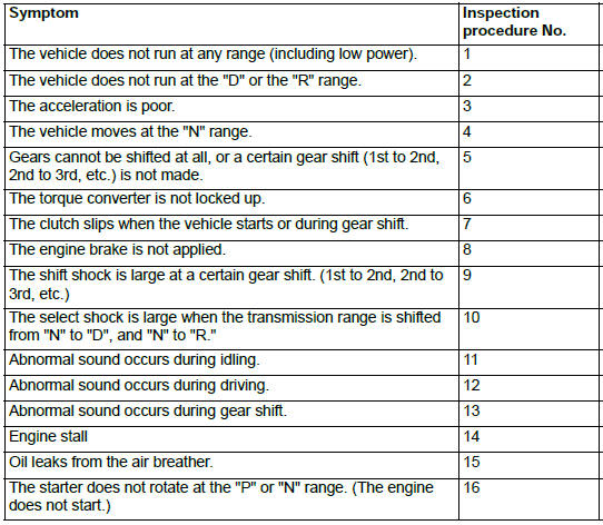
SYMPTOM CHART
CAUTION During diagnosis, a DTC code associated with other system may be set when the ignition switch is turned on with connector(s) disconnected. On completion, confirm all systems for DTC code(s).
If DTC code(s) are set, erase them all.
- DTC P0703, P0705, P0712, P0713, P0715, P0720, P0729, P0731, P0732, P0733, P0734, P0735, P0736
- DTC P0741, P0742, P0743, P0748, P0753, P0758, P0763, P0768, P0815, P0816, P0826, P0846
- DTC P0876, P0893, P0988, P1705, P1706, P1731, P1753, P1758, P1773, P1796, U0001, U0100, U0121, U0141
- Inspection Procedure
READ NEXT:
 DTC P0703, P0705, P0712, P0713, P0715, P0720, P0729, P0731, P0732,
P0733, P0734, P0735, P0736
DTC P0703, P0705, P0712, P0713, P0715, P0720, P0729, P0731, P0732,
P0733, P0734, P0735, P0736
DTC P0703: Stoplight Switch Malfunction
Stoplight switch system circuit
DESCRIPTIONS OF MONITOR METHODS
Drive the vehicle at 30 km/h (18.6 mph) or more
for 10 seconds, and then turn the ignition
DTC P0741, P0742, P0743, P0748, P0753, P0758, P0763, P0768, P0815,
P0816, P0826, P0846
DTC P0741: Torque Converter Clutch System (Stuck Off), P0742 Torque
Converter Clutch System
(Stuck ON)
DESCRIPTIONS OF MONITOR METHODS
<P0741>
When the input shaft speed sensor is normal, the
DTC P0876, P0893, P0988, P1705, P1706, P1731, P1753, P1758, P1773,
P1796, U0001, U0100, U0121, U0141
DTC P0876: High Clutch Pressure Switch System
DESCRIPTIONS OF MONITOR METHODS
With the solenoid failure not detected and with
4th to 6th gear driving, the switch OFF status
continues for 2 seconds
SEE MORE:
Symptom Procedures
Inspection Procedure 1: None of headlights (low-beam) illuminates.
CAUTION
Whenever the ECU is replaced, ensure that the
power supply circuit, the ground circuit and the
communication circuit are normal.
Headlight Relay (Low-Beam) Circuit <Halogen Type>
Headlight Relay (Low-Beam) Circuit <
Engine Cooling Diagnosis
INTRODUCTION
The system cools the engine so that it does not overheat
and maintains the engine at an optimum temperature.
The system components are the radiator,
water pump, thermostat, condenser fan assembly.
Possible faults include low coolant, contamination,
belt loosening and component damage
