Mitsubishi Outlander: Intake Manifold and Fuel System
REMOVAL AND INSTALLATION
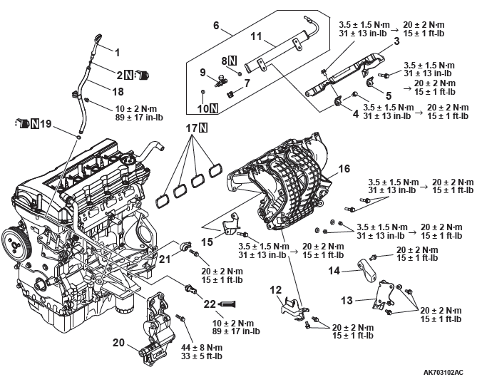
Removal steps
- Oil dipstick rod
- O-ring
- Injector protector rear
- Bracket
- Bracket
- Fuel rail assembly
- Injection support
- O-ring
- Injector
- O-ring
- Fuel rail
- Intake manifold stay
- Intake manifold stay B
- Intake manifold stay C
- Injector protector front
- Intake manifold
- Intake manifold gasket
- Oil dipstick guide
- O-ring
- Generator bracket
- Detonation sensor
- Engine oil pressure switch
Required Special Tool:
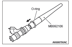
- MB992106: O-ring installer
INSTALLATION SERVICE POINTS
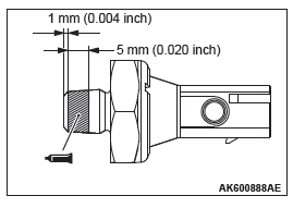
ENGINE OIL PRESSURE SWITCH INSTALLATION
CAUTION
- Do not allow sealant to squeeze out to the screw tip.
- Do not tighten, exceeding the specified tightening torque.
1. Completely remove sealant adhering to the oil pressure switch and cylinder block threaded holes.
2. Apply sealant of 5 mm to the threaded portion of the oil pressure switch shown in the illustration.
Specified sealant: Three bond 1212D, Three bond 1215 or equivalent
3. Tighten the oil pressure switch to the cylinder block to the specified tightening torque.
Tightening torque: 10 +- 2 N*m (89 +- 17 in-lb)
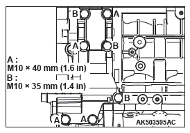
GENERATOR BRACKET INSTALLATION
Tighten the Generator bracket to the specified tightening torque.
Tightening torque: 44 +- 8 N*m (33 +- 5 ft-lb)
NOTE: Be careful to install mounting bolts because they are different in length.
INTAKE MANIFOLD INSTALLATION
CAUTION
Temporarily tighten the inlet manifold because there is a bolt tightening procedure for the inlet manifold, delivery pipe and injector protector.
Tighten each inlet manifold bolt and nut to the temporarily torque of 3.5 +- 1.5 N*m (31 +- 13 in-lb).
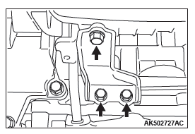
INLET MANIFOLD STAY INSTALLATION
Make sure that the inlet manifold stay is in intimate contact with the inlet manifold and cylinder block boss before tightening it to the specified tightening torque.
Tightening torque: 20 +- 2 N*m (15 +- 1 ft-lb)
O-RING INSTALLATION
1. Apply gasoline to the O-ring.
2. When inserting an O-ring into the injector on the injection nozzle side, use special tool MB992106 to gradually expand the O-ring, and fit it in place.
INJECTOR AND INJECTOR SUPPORT INSTALLATION
CAUTION
Do not allow gasoline to enter the delivery pipe.
1. Apply gasoline to the O-ring of the injector.
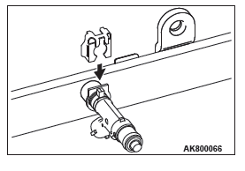
2. Insert the injector into the delivery pipe while rotating the injector from side to side, taking care not to damage the O-ring.
3. Check that the injector rotates smoothly. If it does not rotate smoothly, the O-ring may be caught. Remove the injector and check the O-ring for damage. Then, insert it again into the delivery pipe and check.
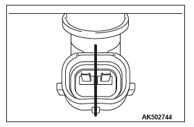
4. Make sure that the protrusion of the injector is at the center as shown in the illustration.
5. Securely assemble the injector to the injector groove and delivery pipe collar.
FUEL RAIL ASSEMBLY / BRACKET / INJECTOR PROTECTOR REAR INSTALLATION
1. Install the delivery pipe assembly, bracket and injector protector rear on the cylinder head.
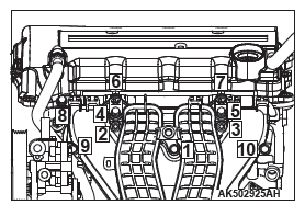
2. Tighten mounting bolts together with temporarily tightened inlet manifold mounting bolts in the order shown in the illustration.
3. Tighten the delivery pipe assembly, bracket, injector protector rear and inlet manifold in the order shown in the illustration.
Temporaliy torque: 3.5 +- 1.5 N*m (31 +- 13 in-lb)
Tightening torque: 20 +- 2 N*m (15 +- 1 ft-lb)
READ NEXT:
 Exhaust Manifold
REMOVAL AND INSTALLATION
<4WD>
Removal steps
Exhaust manifold bracket C
Exhaust manifold bracket A
Crankshaft position sensor cover
Crankshaft position sensor
O-ring
Exhaust manifold upp
Oil Pan and Timing Chain Case
REMOVAL AND INSTALLATION
Removal steps
Breather hose
PCV hose
Positive Crankcase Ventilation
Valve
Positive Crankcase Ventilation
Valve gasket
Oil filler cap
O-ring
Oil drain plug
Oil drai
Timing Chain
REMOVAL AND INSTALLATION
Removal steps
Timing chain tensioner
Tensioner lever
Timing chain guide
Timing chain
Exhaust V.V.T. sprocket bolt
Exhaust V.V.T. sprocket assembly
Intake V.V.T. sproc
SEE MORE:
Cylinder Head Gasket
REMOVAL AND INSTALLATION
Pre-removal operation
Fuel Line Pressure Reduction
Engine Room Under Cover Front B and Engine Room
Side Cover (RH) Removal
Engine Coolant Draining
Air Cleaner Assembly Removal
Ignition Coil Removal
Strut Tower Bar Removal
Exhaust Manifold Removal
Throttle Bod
Wiper and washer switch
Windscreen wipers
The windscreen wipers can be operated with the ignition switch in the “ON” or
“ACC” position.
If the blades are frozen to the windscreen or rear window, do not operate the
wipers until the ice has melted and the blades are freed, otherwise the wiper motor
may be dam
