Mitsubishi Outlander: Exhaust Manifold
REMOVAL AND INSTALLATION
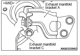
<4WD>
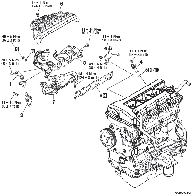
Removal steps
- Exhaust manifold bracket C
- Exhaust manifold bracket A
- Crankshaft position sensor cover
- Crankshaft position sensor
- O-ring
- Exhaust manifold upper cover
- Exhaust manifold lower cover
- Exhaust manifold
- Exhaust manifold gasket
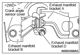
<2WD - Except vehicles for California>
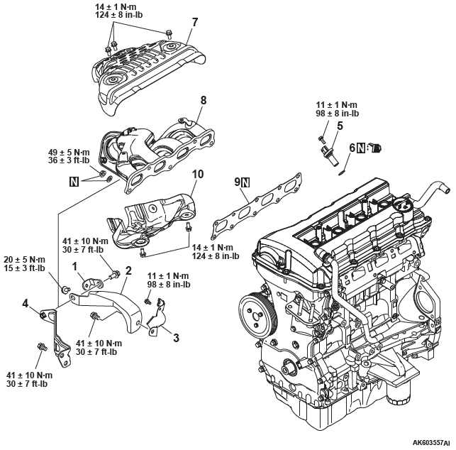
Removal steps
- Exhaust manifold bracket D
- Exhaust manifold bracket B
- Crankshaft position sensor cover
- Exhaust manifold bracket A
- Crankshaft position sensor
- O-ring
- Exhaust manifold upper cover
- Exhaust manifold
- Exhaust manifold gasket
- Exhaust manifold lower cover
<2WD - Vehicles for California>
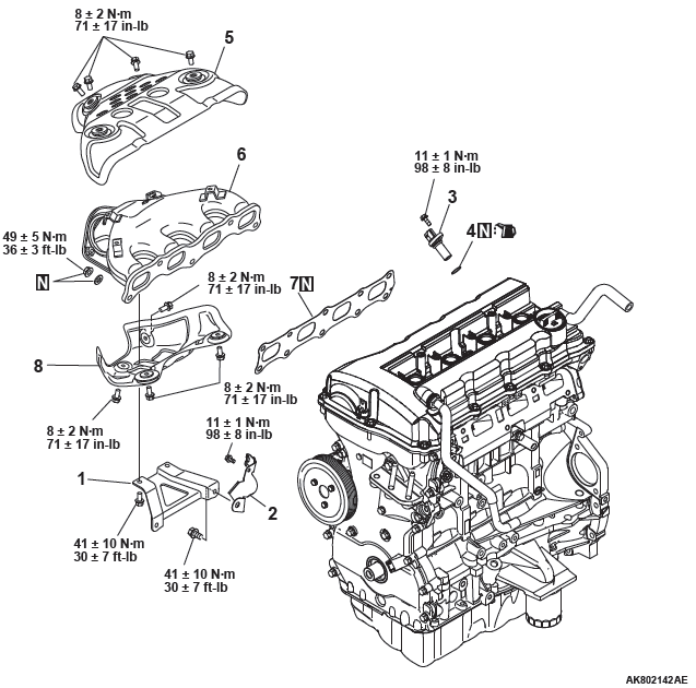
Removal steps
- Exhaust manifold bracket
- Crankshaft position sensor cover
- Crankshaft position sensor
- O-ring
- Exhaust manifold upper cover
- Exhaust manifold
- Exhaust manifold gasket
- Exhaust manifold lower cover
INSTALLATION SERVICE POINTS
EXHAUST MANIFOLD BRACKET INSTALLATION
CAUTION
The exhaust manifold gasket, washers and nuts must not be reused.
CRANKSHAFT POSITION SENSOR / O-RING INSTALLATION
CAUTION
- Do not apply a force such as torsion or twist to the O-ring during assembly of the sensor.
- Assemble the sensor, taking care not to give a shock to it.
- Do not use a sensor that has fallen down.
Tighten the crank angle sensor to the specified tightening torque of 11 +- 1 N*m.
EXHAUST MANIFOLD BRACKET INSTALLATION
Make sure that exhaust manifold bracket A is in intimate contact with the exhaust manifold and cylinder block, and then tighten it to the specified tightening torque.
Tightening torque:
M10: 41 +- 10 N*m (30 +- 7 ft-lb)
M8: 20 +- 5 N*m (15 +- 3 ft-lb)
Water Hose and Pipe
REMOVAL AND INSTALLATION
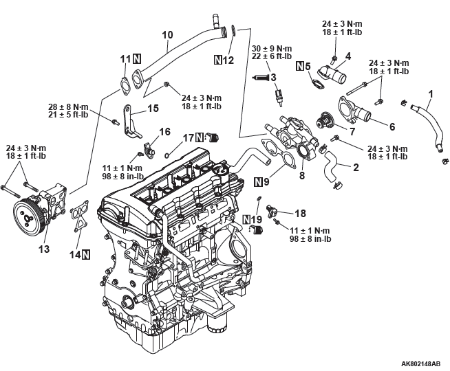
Removal steps
- Water hose
- Water hose
- Engine coolant temperature sensor
- Water outlet fitting
- Outlet fitting gasket
- Water inlet fitting
- Thermostat
- Thermostat housing
- Thermostat housing gasket
- Water pipe assembly
- Water pipe gasket
- O-ring
- Water pump assembly
- Water pump gasket
- Engine hanger
- Camshaft position sensor
- O-ring
- Camshaft position sensor
- O-ring
INSTALLATION SERVICE POINTS
THERMOSTAT HOUSING / WATER PIPE ASSEMBLY INSTALLATION
Assemble the thermostat housing and water pipe, and temporarily tighten them to the cylinder head and water pump. Then tighten them to the specified tightening.
Tightening torque: 24 +- 3 N*m (18 +- 1 ft-lb)
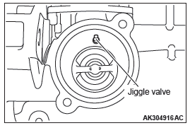
THERMOSTAT INSTALLATION
Install the thermostat with the jiggle-valve facing almost straight upwards.
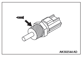
ENGINE COOLANT TEMPERATURE SENSOR INSTALLATION
CAUTION
Be careful not to give a shock, twist and the like to the resin mold with a tool during installation.
1. Apply an appropriate and minimum amount of sealant to the coolant temperature sensor, taking care not to allow sealant to squeeze out.
Specified sealant: Three bond 1324N, LOCTITE 262 or equivalent
2. Tighten the coolant temperature sensor to the cylinder block to the specified tightening torque.
Tightening torque: 30 +- 9 N*m (22 +- 6 ft-lb)
READ NEXT:
 Oil Pan and Timing Chain Case
REMOVAL AND INSTALLATION
Removal steps
Breather hose
PCV hose
Positive Crankcase Ventilation
Valve
Positive Crankcase Ventilation
Valve gasket
Oil filler cap
O-ring
Oil drain plug
Oil drai
Timing Chain
REMOVAL AND INSTALLATION
Removal steps
Timing chain tensioner
Tensioner lever
Timing chain guide
Timing chain
Exhaust V.V.T. sprocket bolt
Exhaust V.V.T. sprocket assembly
Intake V.V.T. sproc
Camshaft
REMOVAL AND INSTALLATION
Removal steps
Engine oil control valve (OCV)
exhaust
O-ring
Engine oil control valve (OCV)
intake
O-ring
Front camshaft bearing cap
Oil feeding camshaft bearing cap
SEE MORE:
Window Glass Runchannel and Door Opening Weatherstrip
REMOVAL AND INSTALLATION
<Front door>
Waterproof film removal steps
Pull handle bracket
Waterproof film
Door window glass runchannel
removal steps
Door window glass runchannel
Door belt line weatherstrip inner
removal steps
Door trim assembly
Door belt line weatherstrip inner
Combination headlamps and dipper switch
Headlamps
NOTE:
● Do not leave the lights on for a long time while the engine is stationary (not
running). A rundown battery could result.
● When it rains, or when the vehicle has been washed, the inside of the lens
sometimes becomes foggy, but this does not indicate a functional
