Mitsubishi Outlander: DTC P0703, P0705, P0712, P0713, P0715, P0720, P0729, P0731, P0732, P0733, P0734, P0735, P0736
DTC P0703: Stoplight Switch Malfunction
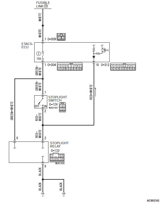
Stoplight switch system circuit
DESCRIPTIONS OF MONITOR METHODS
- Drive the vehicle at 30 km/h (18.6 mph) or more for 10 seconds, and then turn the ignition switch to the "LOCK" (OFF) position. In this sequential operation, no variation has been found in the stoplight switch input signal in two consecutive times.
MONITOR EXECUTION
- Drive with the vehicle speed 30 km/h (18.6 mph) or more for 10 seconds or more.
MONITOR EXECUTION CONDITIONS (OTHER MONITOR AND SENSOR)
Other Monitor (There is no temporary DTC stored in memory for the item monitored below)
- Not applicable
Sensor (The sensor below is determined to be normal)
- Not applicable
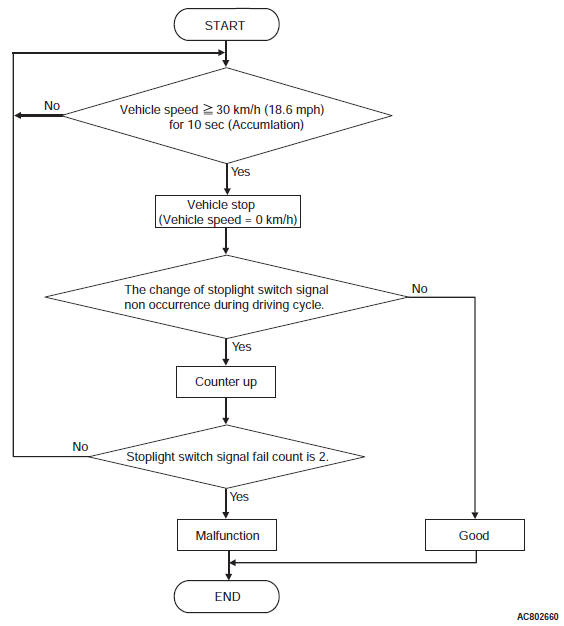
LOGIC FLOW CHARTS (Monitor Sequence)
DTC SET CONDITIONS
Check Conditions
- Vehicle speed over 30 km/h (18.6 mph): 10 seconds or more.
Judgment Criteria
- The change of brake switch signal during driving cycle: no occurrence. (10 seconds)
- Stoplight switch signal fail: 2 count or more. (10 seconds)
OBD-II DRIVE CYCLE PATTERN
Drive with the vehicle speed 30 km/h (18.6 mph) or more for 10 seconds or more, and then stop the vehicle.
Again, drive with the vehicle speed 30 km/h (18.6 mph) or more for 10 seconds or more, and then stop the vehicle.
PROBABLE CAUSES
- Malfunction of the CAN bus
- Malfunction of the stoplight switch
- Damaged wiring harness and connectors
- Malfunction of TCM
- Malfunction of ETACS-ECU
DIAGNOSTIC PROCEDURE
STEP 1. Using scan tool MB991958, diagnose the CAN bus line.
Use scan tool to perform the CAN bus diagnosis.
Q: Is the check result normal?
YES : Go to Step 2.
NO : Repair the CAN bus lines.
STEP 2. M.U.T.-III data list
Item 60: Brake switch
OK: The service data changes in response to the brake operation.
Q: Is the check result normal?
YES : Intermittent malfunction
NO : Go to Step 3.
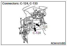
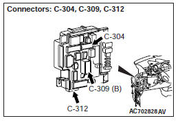
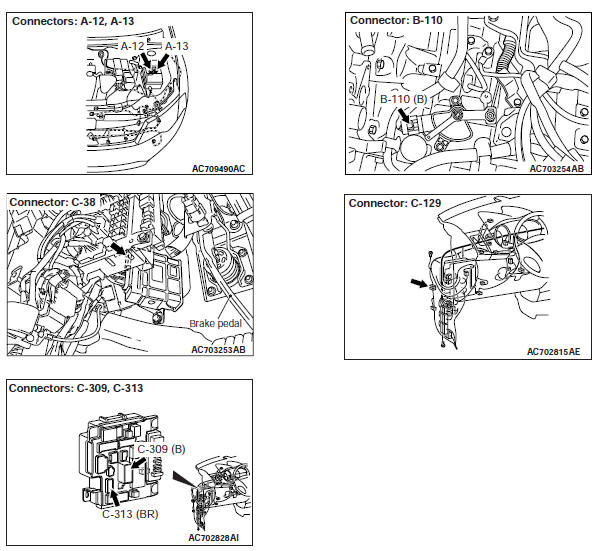
STEP 3. Check the following connector:
- C-304 ETACS-ECU connector
- C-312 ETACS-ECU connector
- C-124 Stoplight switch connector
Check the contact status of the terminals.
Q: Is the check result normal?
YES : Go to Step 4.
NO : Repair the defective connector.
STEP 4. Stoplight Switch Check
Q: Is the check result normal?
YES : Go to Step 5.
NO : Replace the stoplight switch.
STEP 5. Check for open circuit in the wiring harness between the stoplight switch connector and the ETACS-ECU connector.
Between C-124 Stoplight switch connector (terminal No.1) and C-304 ETACS-ECU harness-side connector (terminal No.1)
Q: Is the check result normal?
YES : Go to Step 6.
NO : Repair the wiring harness.
STEP 6. Check for open circuit or short to ground in wiring harness between the stoplight switch connector and the ETACS-ECU
Between C-124 Stoplight switch connector (terminal No. 2) and C-312 ETACS-ECU harness-side connector (terminal No. 16)
Q: Is the check result normal?
YES : Go to Step 7.
NO : Repair the wiring harness.
STEP 7. Symptom recheck after erasing diagnostic trouble code
Q: Is the check result normal?
YES : Intermittent malfunction
NO : Replace the ETACS-ECU, and then go to Step 8.
STEP 8. Symptom recheck after erasing diagnostic trouble code
Q: Is the check result normal?
YES : Intermittent malfunction
NO : Replace TCM.
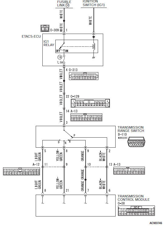
DTC P0705: Transmission Range Switch System
Transmission range switch system circuit
DESCRIPTIONS OF MONITOR METHODS
- The TCM receives no input signal from the transmission range switch.
- The TCM receives multiple input signals simultaneously from the transmission range switch.
MONITOR EXECUTION
- Continuous
MONITOR EXECUTION CONDITIONS (OTHER MONITOR AND SENSOR)
Other Monitor (There is no temporary DTC stored in memory for the item monitored below)
- P0712: Malfunction of the transmission fluid temperature sensor (Short circuit)
- P0731: Malfunction of the 1st gear incorrect ratio
- P0732: Malfunction of the 2nd gear incorrect ratio
- P0733: Malfunction of the 3rd gear incorrect ratio
- P0734: Malfunction of the 4th gear incorrect ratio
- P0735: Malfunction of the 5th gear incorrect ratio
- P0729: Malfunction of the 6th gear incorrect ratio
- P0736: Malfunction of the Reverse gear incorrect ratio
- P0742: Malfunction of the Torque converter clutch system (Stuck on)
- P0846: Malfunction of the 2-6 brake pressure switch system
- P0876: Malfunction of the High clutch pressure switch system
- P0988: Malfunction of the Low-reverse brake pressure switch system
Sensor (The sensor below is determined to be normal)
- Transmission fluid temperature sensor
LOGIC FLOW CHARTS (Monitor Sequence)
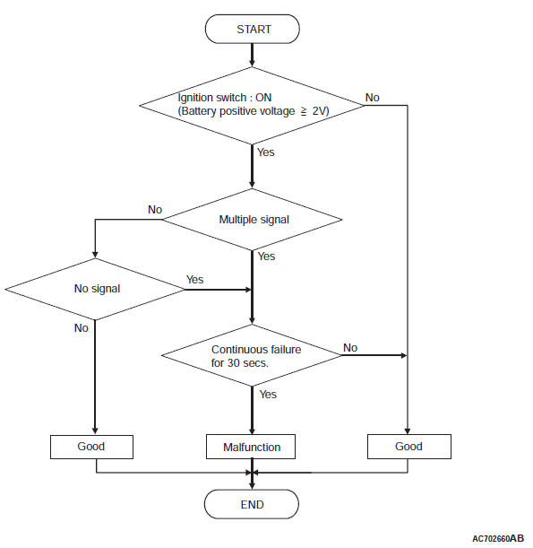
DTC SET CONDITIONS
Check Conditions
- Voltage of battery: 2 volts or more.
Judgment Criteria
- Transmission range switch: no signal detected. (30 seconds)
- Transmission range switch: multiple signal. (30 seconds)
OBD-II DRIVE CYCLE PATTERN
Start the engine, keep the vehicle stopped in "P", "R", "N", "D" ranges respectively for more than one minute, and turn "LOCK" (OFF) the ignition switch.
Then restart the engine, and stop the vehicle in "P", "R", "N", "D" ranges respectively for more than one minute.
TROUBLESHOOTING HINTS (THE MOST LIKELY CAUSES FOR THIS CODE TO BE SET ARE:)
- Malfunction of the transmission range switch system circuit
- Damaged harness or connector
- Improper installation angle of transmission range switch
- Malfunction of the transmission range switch
- Malfunction of the TCM
DIAGNOSIS
STEP 1. Check the TCM terminal voltage.
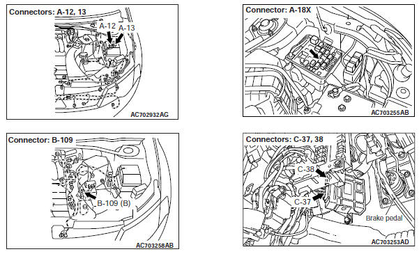
[C-38 TCM connector (vehicle side, connected) ]
Turn ON the ignition switch, and check by shifting to each range.
- "P" range: Terminal No. 6 to body ground → Battery positive voltage
- "R" range: Terminal No. 7 to body ground → Battery positive voltage
- "N" range: Terminal No. 21 to body ground → Battery positive voltage
- "D" range: Terminal No. 8 to body ground → Battery positive voltage
Q: Is the check result normal?
YES : Go to Step 6.
NO : Go to Step 2.
STEP 2. Check the path between the ignition switch and the transmission range switch.
Turn OFF the ignition switch, and check the following items.
- Open/short circuit of wiring harness between the ignition switch and B-110 transmission range switch connector terminal No. 3.
- Blown fuse
Q: Is the check result normal?
YES : Go to Step 3.
NO : Repair or replace the failure section.
STEP 3. Check the wiring harness between the transmission range switch and TCM.
Check for continuity between B-110 transmission range switch terminals and C-38 TCM terminals.
NOTE: Prior to the wiring harness inspection, check the intermediate connectors A-12 and A-13, and repair that if necessary.
- Between B-110 terminal No. 2 and C-38 terminal No. 6: At the "P" range, continuity exists.
- Between B-110 terminal No. 9 and C-38 terminal No. 7: At the "R" range, continuity exists.
- Between B-110 terminal No. 8 and C-38 terminal No. 21: At the "N" range, continuity exists.
- Between B-110 terminal No. 5 and C-38 terminal No. 8: At the "D" range, continuity exists.
When the continuity check result is OK, check that the wiring harness is not shorted to the body and other wiring harness.
Q: Is the check result normal?
YES : Go to Step 4.
NO : Repair or replace the failure section.
STEP 4. Check the transmission range switch as a single unit.
Q: Is the check result normal?
YES : Go to Step 5.
NO : Go to Step 7.
STEP 5. Check the TCM connector pin terminal and the connection status.
Q: Is there a failure point?
YES : Repair or replace the failure section.
NO : Replace the TCM.
STEP 6. Erase the DTC code, and drive the vehicle for a while.
Check that the normal code is displayed.
Q: Is the check result normal?
YES : The procedure is complete.
NO : Replace the TCM.
STEP 7. Adjust the transmission range switch.
After adjustment, check the continuity between the terminals again.
Q: Is the check result normal?
YES : Go to Step 8.
NO : Replace the transmission range switch.
STEP 8. Erase the DTC code, and drive the vehicle for a while.
Check that the normal code is displayed.
Q: Is the check result normal?
YES : The procedure is complete.
NO : Return to START.
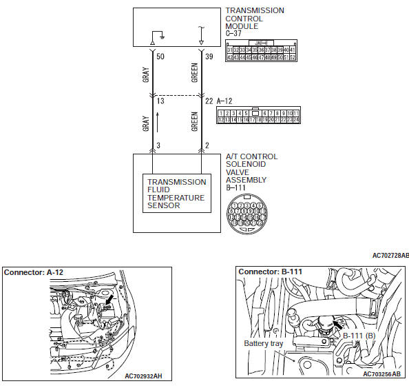
DTC P0712: Transmission Fluid Temperature Sensor System (Short Circuit)
Transmission fluid temperature sensor circuit
DESCRIPTIONS OF MONITOR METHODS
- When the status of transmission fluid temperature 180ºC (356ºF) or more is detected for 10 minutes continuously with the conditions as follows; Vehicle speed: 10 km/h (6.2 mph) or more, transmission range switch position: D, accelerator pedal position: 12.5% or more, engine speed: more than 500 r/min
MONITOR EXECUTION
- transmission range: D
- Vehicle speed: more than 10 km/h (6.2 mph)
- Throttle valve opening: more than 1/8
- Engine speed: more than 305 r/min
MONITOR EXECUTION CONDITIONS (OTHER MONITOR AND SENSOR)
Other Monitor (There is no temporary DTC stored in memory for the item monitored below)
- Not applicable
Sensor (The sensor below is determined to be normal)
- Not applicable
LOGIC FLOW CHARTS (Monitor Sequence)
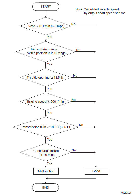
DTC SET CONDITIONS
Check Conditions
- Vehicle speed: 10 km/h (6.2 mph) or more.
- Transmission range switch position: D.
- Throttle opening: 12.5 % or more.
- Engine speed: more than 500 r/min.
Judgment Criteria
- Value of temperature of transmission fluid: 180ºC (356ºF) or more. (10 minutes)
OBD-II DRIVE CYCLE PATTERN
With the vehicle speed 10 km/h (6.2 mph) or more and the throttle valve opening 12.5% or more, drive for 10 minutes or more.
TROUBLESHOOTING HINTS (THE MOST LIKELY CAUSES FOR THIS CODE TO BE SET ARE:)
- Malfunction of the transmission fluid temperature sensor system (Short circuit) circuit
- Malfunction of the transmission fluid temperature sensor
- Malfunction of the TCM
DIAGNOSIS
STEP 1. Check the TCM terminal voltage.
[C-38 TCM connector (vehicle side, connected) ]
Turn ON the ignition switch, and check the voltage between terminal No. 39 and No. 50.
- Transmission fluid 20ºC (68ºF): Approx. 2.52 V
- Transmission fluid 80ºC (176ºF): Approx. 0.69 V
Q: Is the check result normal?
YES : Go to Step 6.
NO : Go to Step 2.
STEP 2. Check the transmission fluid temperature sensor.
Q: Is the check result normal?
YES : Go to Step 3.
NO : Replace the valve body assembly.
STEP 3. Check the wiring harness between the transmission fluid temperature sensor and TCM. Check that the wiring harness between the A/T control solenoid valve assembly connector and TCM is not shorted to the body and other wiring harness.
Q: Is the check result normal?
YES : Go to Step 4.
NO : Repair or replace the failure section.
STEP 4. Check the TCM power supply and ground.
Q: Is the check result normal?
YES : Go to Step 5.
NO : Repair or replace the failure section.
STEP 5. Check the TCM connector pin terminal and the connection status.
Q: Is there a failure point?
YES : Repair or replace the failure section.
NO : Replace the TCM.
STEP 6. Erase the DTC code, and drive the vehicle for a while.
Check that the normal code is displayed.
Q: Is the check result normal?
YES : The procedure is complete.
NO : Replace the TCM.
DTC P0713: Transmission Fluid Temperature Sensor System (Open Circuit)
DESCRIPTIONS OF MONITOR METHODS
- With the vehicle speed 10 km/h (6.2 mph) or more, when the status of transmission fluid temperature −40ºC (−104ºF) or less is detected
MONITOR EXECUTION
- Vehicle speed: more than 10 km/h (6.2 mph)
MONITOR EXECUTION CONDITIONS (OTHER MONITOR AND SENSOR)
Other Monitor (There is no temporary DTC stored in memory for the item monitored below)
- P0846: Malfunction of the 2-6 brake pressure switch system
- P0876: Malfunction of the High clutch pressure switch system
- P0988: Malfunction of the Low-reverse brake pressure switch system
Sensor (The sensor below is determined to be normal)
- Not applicable
LOGIC FLOW CHARTS (Monitor Sequence)
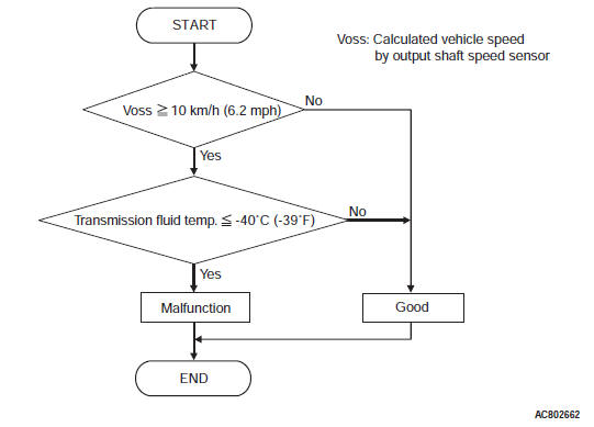
DTC SET CONDITIONS
Check Conditions
- Vehicle speed: 10 km/h (6.2 mph) or more.
Judgment Criteria
- Value of temperature of transmission fluid: -40ºC (-104ºF) or less. (At once)
OBD-II DRIVE CYCLE PATTERN
Drive with the vehicle speed 10 km/h (6.2 mph) or more.
TROUBLESHOOTING HINTS (THE MOST LIKELY CAUSES FOR THIS CODE TO BE SET ARE:)
- Malfunction of the transmission fluid temperature sensor system (open circuit) circuit
- Damaged harness or connector
- Malfunction of the transmission fluid temperature sensor system (open circuit)
- Malfunction of the TCM
DIAGNOSIS
STEP 1. Check the TCM terminal voltage.
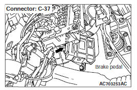
[C-37 connector (vehicle side, connected) ]
Turn ON the ignition switch, and check the voltage between terminal No. 39 and No. 50.
- Transmission fluid 20ºC (68ºF): Approx. 2.52 V
- Transmission fluid 80ºC (176ºF): Approx. 0.69 V
Q: Is the check result normal?
YES : Go to Step 6.
NO : Go to Step 2.
STEP 2. Check the transmission fluid temperature sensor as a single unit.
Q: Is the check result normal?
YES : Go to Step 3.
NO : Replace the valve body assembly.
STEP 3. Check the wiring harness between the transmission fluid temperature sensor and TCM.
Check for continuity between B-111 A/T control solenoid valve assembly connector terminals and C-37 TCM terminals.
NOTE: Prior to the wiring harness inspection, check the intermediate connectors A-12 and repair that if necessary.
- Between B-111 terminal No. 2 and C-37 terminal No. 39: Continuity exists.
- Between B-111 terminal No. 3 and C-37 terminal No. 50: Continuity exists.
When the continuity check result is OK, check that the wiring harness is not shorted to the body and other wiring harness.
Q: Is the check result normal?
YES : Go to Step 4.
NO : Repair or replace the failure section.
STEP 4. Check the TCM power supply and ground.
Q: Is the check result normal?
YES : Go to Step 5.
NO : Repair or replace the failure section.
STEP 5. Check the TCM connector pin terminal and the connection status.
Q: Is there a failure point?
YES : Repair or replace the failure section.
NO : Replace the TCM.
STEP 6. Erase the DTC code, and drive the vehicle for a while.
Check that the normal code is displayed.
Q: Is the check result normal?
YES : The procedure is complete.
NO : Return to START.
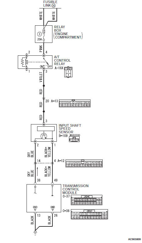
DTC P0715: Input Shaft Speed Sensor System
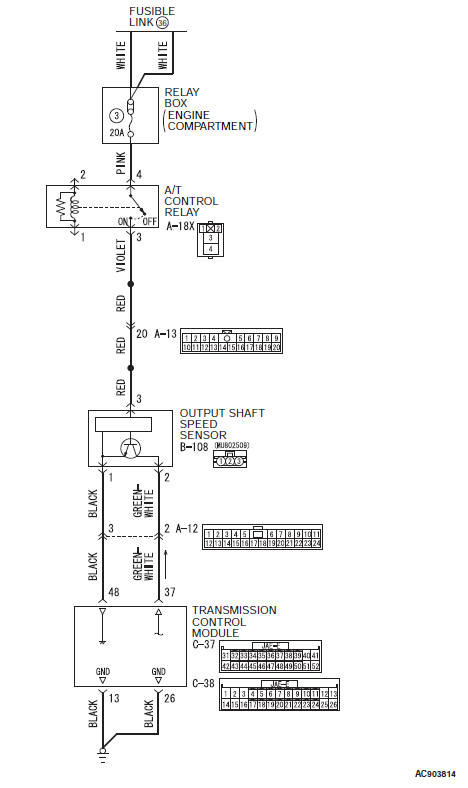
Input shaft speed sensor system circuit
DESCRIPTIONS OF MONITOR METHODS
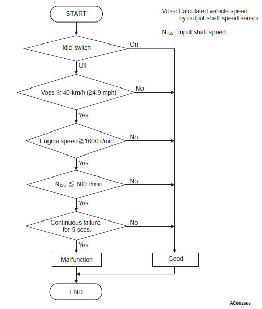
- With the idle switch OFF, vehicle speed 40 km/h (24.9 mph) or more, and engine speed 1,600 r/min or more, when the status of input shaft speed 600 r/min or less is detected for 5 seconds continuously
MONITOR EXECUTION
- Vehicle speed: 40 km (24.9 mph) or more
- Engine speed: 1,600 r/min or more
MONITOR EXECUTION CONDITIONS (OTHER MONITOR AND SENSOR)
Other Monitor (There is no temporary DTC stored in memory for the item monitored below)
- P0731: Malfunction of the 1st gear incorrect ratio
- P0732: Malfunction of the 2nd gear incorrect ratio
- P0733: Malfunction of the 3rd gear incorrect ratio
- P0734: Malfunction of the 4th gear incorrect ratio
- P0735: Malfunction of the 5th gear incorrect ratio
- P0729: Malfunction of the 6th gear incorrect ratio
- P0736: Malfunction of the Reverse gear incorrect ratio
- P0741: Malfunction of the Malfunction of the Torque converter clutch system (Stuck off)
- P0742: Malfunction of the Torque converter clutch system (Stuck on)
- P0846: Malfunction of the 2-6 brake pressure switch system
- P0876: Malfunction of the High clutch pressure switch system
- P0988: Malfunction of the Low-reverse brake pressure switch system
Sensor (The sensor below is determined to be normal)
- Not applicable
LOGIC FLOW CHARTS (Monitor Sequence)
DTC SET CONDITIONS
Check Conditions
- Idle switch: OFF.
- Vehicle speed: 40 km/h (24.9 mph) or more.
- Engine speed: 1,600 r/min or more.
Judgment Criteria
- Input shaft speed sensor signal: 600 r/min. or less (5 seconds)
OBD-II DRIVE CYCLE PATTERN
Drive with the vehicle speed 40 km/h (24.9 mph) or more, and engine speed 1,600 r/min or more.
TROUBLESHOOTING HINTS (THE MOST LIKELY CAUSES FOR THIS CODE TO BE SET ARE:)
- Malfunction of the Input shaft speed sensor system circuit
- Damaged harness or connector
- Malfunction of the Input shaft speed sensor
- Malfunction of the TCM
- Malfunction of the input shaft speed sensor rotor (A/T assembly)
DIAGNOSIS
STEP 1. Check the TCM terminal voltage and frequency.
[C-37 TCM connector (vehicle side, connected) ]
Check that the voltage between C-37 terminal No. 49 and C-38 terminal No. 13 or C-38 terminal No. 26 is 0 V, and then check the frequency of C-37 terminal No. 38.
- At D range, and the engine speed is 700 r/min: Approx. 353 Hz
Q: Is the check result normal?
YES : Go to Step 8.
NO : Go to Step 2.
STEP 2. Check the power supply and sensor ground.
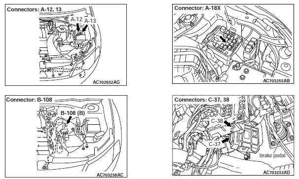
[B-109 input shaft speed sensor connector (vehicle side, disconnected) ]
- With the ignition switch ON: Terminal No. 3 to terminal No. 1 → Battery positive voltage
Q: Is the check result normal?
YES : Go to Step 3.
NO : Go to Step 4.
STEP 3. Check the wiring harness between the input shaft speed sensor and TCM.
Check for continuity between B-109 input shaft speed sensor connector terminals and C-37 TCM terminals.
NOTE: Prior to the wiring harness inspection, check the intermediate connectors A-12 and repair that if necessary.
- Between B-109 terminal No. 2 and C-37 terminal No. 38: Continuity exists.
When the continuity check result is OK, check that the wiring harness is not shorted to the body and other wiring harness.
Q: Is the check result normal?
YES : Replace the input shaft speed sensor with the one of the same transaxle of the same model. Then go to Step 5.
NO : Repair or replace the failure section, and then go to Step 8.
STEP 4. Check the path between the fusible link No.36 and the input shaft speed sensor.
- Check the wiring harness for an open/short circuit between the ignition switch and B-109 input shaft speed sensor connector terminal No. 3.
- Check for a blown fuse.
Q: Is the check result normal?
YES : Go to Step 6.
NO : Repair or replace the failure section.
STEP 5. After replacing the input shaft speed sensor, drive the vehicle for a while, and then check the DTC again.
Q: Is the check result normal?
YES : Replace the input shaft speed sensor.
NO : Replace the TCM. Then go to Step 9.
STEP 6. Check the wiring harness between the input shaft speed sensor and TCM.
Check for continuity between B-109 input shaft speed sensor terminals and C-37 TCM terminals.
NOTE: Prior to the wiring harness inspection, check the intermediate connectors A-12 and repair that if necessary.
- Between B-109 terminal No. 1 and C-37 terminal No. 49: Continuity exists.
When the continuity check result is OK, check that the wiring harness is not shorted to the body and other wiring harness.
Q: Is the check result normal?
YES : Go to Step 7.
NO : Repair or replace the failure section.
STEP 7. Check the TCM connector pin terminal and the connection status.
Q: Is there a failure point?
YES : Repair or replace the failure section.
NO : Replace the TCM.
STEP 8. Drive the vehicle for a while.
Check that the normal code is displayed.
Q: Is the check result normal?
YES : The procedure is complete.
NO : Replace the TCM.
STEP 9. Diagnostic trouble code recheck.
1. Erase the diagnostic trouble code.
2. Drive the vehicle at 40 km/h (24.9 mph) or more (engine speed at 1,600 r/min or more).
3. Check if the diagnostic trouble code is set.
Q: Is the diagnostic trouble code set?
YES : Remove the A/T. Carry out the internal check and repair the defective part (the input shaft speed sensor rotor may be defective).
NO : The procedure is complete.
Code No. P0720: Output Shaft Speed Sensor System
Output shaft speed sensor system circuit
DESCRIPTIONS OF MONITOR METHODS
- With the vehicle speed more than 20 km/h (12.4 mph), when the vehicle speed is decelerated by 20 km/h (12.4 mph) or more in 0.05 seconds
MONITOR EXECUTION
- Vehicle speed 20 km/h (12.4 mph) or more.
MONITOR EXECUTION CONDITIONS (OTHER MONITOR AND SENSOR)
Other Monitor (There is no temporary DTC stored in memory for the item monitored below)
- P0712: Malfunction of the transmission fluid temperature sensor (Short circuit)
- P0713: Malfunction of the transmission fluid temperature sensor (Open circuit)
- P0731: Malfunction of the 1st gear incorrect ratio
- P0732: Malfunction of the 2nd gear incorrect ratio
- P0733: Malfunction of the 3rd gear incorrect ratio
- P0734: Malfunction of the 4th gear incorrect ratio
- P0735: Malfunction of the 5th gear incorrect ratio
- P0729: Malfunction of the 6th gear incorrect ratio
- P0736: Malfunction of the Reverse gear incorrect ratio
- P0742: Malfunction of the Torque converter clutch system (Stuck on)
- P0846: Malfunction of the 2-6 brake pressure switch system
- P0876: Malfunction of the High clutch pressure switch system
- P0988: Malfunction of the Low-reverse brake pressure switch system
- P0893: Malfunction of the Interlock detection
- P1705: Malfunction of the Throttle position sensor information (engine)
- P1773: Malfunction of the ABS information (ASC)
Sensor (The sensor below is determined to be normal)
- Transmission fluid temperature sensor
LOGIC FLOW CHARTS (Monitor Sequence)
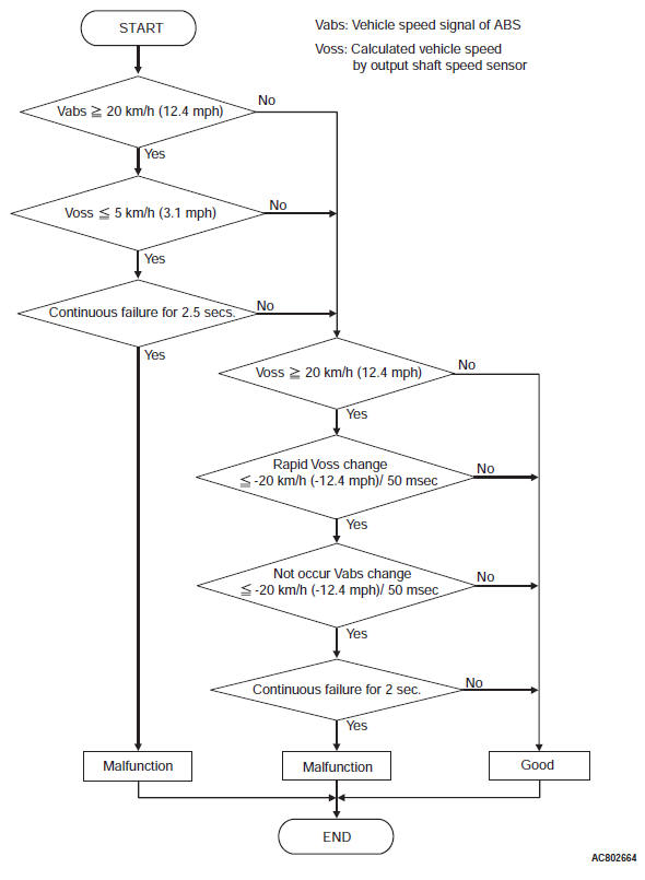
DTC SET CONDITIONS
Check Conditions
- Vehicle speed: 20 km/h (12.4 mph) or more.
- Vehicle speed signal from ABS: more than -20 km/h (-12.4 mph)/0.05 seconds.
Judgment Criteria
- Rapid vehicle speed change: -20 km/h (-12.4 mph)/0.05 second or less. (2 seconds)
Check Conditions
- Vehicle speed signal from ABS: 20 km/h (12.4 mph) or more.
Judgment Criteria
- Vehicle speed: 5 km/h (3.1 mph) or less. (2.5 seconds)
OBD-II DRIVE CYCLE PATTERN
Drive with the vehicle speed 20 km/h (12.4 mph).
TROUBLESHOOTING HINTS (THE MOST LIKELY CAUSES FOR THIS CODE TO BE SET ARE:)
- Malfunction of the output shaft speed sensor system circuit
- Damaged harness or connector
- Malfunction of the output shaft speed sensor
- Malfunction of the TCM
- Malfunction of the output shaft speed sensor rotor (A/T assembly)
DIAGNOSIS
STEP 1. Check the TCM terminal voltage and frequency.
[C-37 TCM connector (vehicle side, connected) ]
Check that the voltage between C-37 terminal No. 48 and C-38 terminal No. 13 or C-38 terminal No. 26 is 0 V, and then check the frequency of C-37 terminal No. 37.
- At D range, vehicle speed is 30 km/h (19 mph): Approx. 588 Hz
Q: Is the check result normal?
YES : Go to Step 6.
NO : Go to Step 2.
STEP 2. Check the power supply and sensor ground.
[B-108 output shaft speed sensor connector (vehicle side, disconnected) ]
- With the ignition switch ON: Terminal No. 1 to No. 3 → Battery positive voltage
Q: Is the check result normal?
YES : Go to Step 3.
NO : Go to Step 4.
STEP 3. Check the wiring harness between the output shaft speed sensor and TCM.
Check for continuity between B-108 output shaft speed sensor terminals and C-37 TCM terminals.
NOTE: Prior to the wiring harness inspection, check the intermediate connectors A-12 and repair that if necessary.
- Between B-108 terminal No. 2 and C-37 terminal No. 37: Continuity exists.
When the continuity check result is OK, check that the wiring harness is not shorted to the body and other wiring harness.
Q: Is the check result normal?
YES : Replace the output shaft speed sensor with the one of the same transaxle of the same model. Then go to Step 7.
NO : Repair or replace the failure section, and then go to Step 6.
STEP 4. Check the path between the ignition switch and the output shaft speed sensor.
- Check the wiring harness for an open/short circuit between the ignition switch and B-108 output shaft speed sensor connector terminal No. 1.
- Check for a blown fuse.
Q: Is the check result normal?
YES : Go to Step 5.
NO : Repair or replace the failure section.
STEP 5. Check the wiring harness between the output shaft speed sensor and TCM.
Check for continuity between B-108 output shaft speed sensor terminals and C-37 TCM terminals.
NOTE: Prior to the wiring harness inspection, check the intermediate connectors A-12 and repair that if necessary.
- Between B-108 terminal No. 1 and C-37 terminal No. 48: Continuity exists.
When the continuity check result is OK, check that the wiring harness is not shorted to the body and other wiring harness.
Q: Is the check result normal?
YES : Go to Step 8.
NO : Repair or replace the failure section.
STEP 6. Drive the vehicle for a while.
Check that the normal code is displayed.
Q: Is the check result normal?
YES : The procedure is complete.
NO : Replace the TCM.
STEP 7. After replacing the output shaft speed sensor, drive the vehicle for a while, and then check the DTC again.
Q: Is the check result normal?
YES : Replace the output shaft speed sensor.
NO : Replace the TCM. Then go to Step 9.
STEP 8. Check the TCM connector pin terminal and the connection status.
Q: Is there a failure point?
YES : Repair or replace the failure section.
NO : Replace the TCM.
STEP 9. Diagnostic trouble code recheck.
1. Erase the diagnostic trouble code.
2. Drive the vehicle at 20 km/h (12.4 mph) or more.
3. Check if the diagnostic trouble code is set.
Q: Is the diagnostic trouble code set?
YES : Remove the A/T. Carry out the internal check and repair the defective part (the output shaft speed sensor rotor may be defective).
NO : The procedure is complete.
DTC P0729, P0732, P0733, P0734, P0735: 6th, 2nd, 3rd, 4th, 5th Gear Ratio
LOGIC FLOW CHARTS (Monitor Sequence)
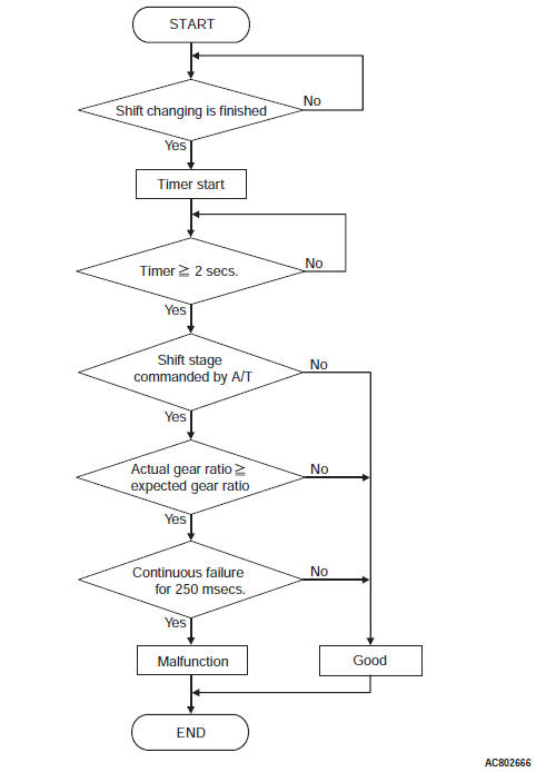
.DESCRIPTIONS OF MONITOR METHODS <DTC P0729>
- After 6th gear is achieved for 2 seconds, the engine runup*1 is detected for 250 milliseconds.
*1: The actual gear ratio deviates from the target gear ratio to the high engine (turbine) speed.
MONITOR EXECUTION <DTC P0729>
- 6th gear driving
MONITOR EXECUTION CONDITIONS (OTHER MONITOR AND SENSOR) <DTC P0729>
Other Monitor (There is no temporary DTC stored in memory for the item monitored below)
- P0846: Malfunction of the 2-6 brake pressure switch system
- P0876: Malfunction of the High clutch pressure switch system
- P0988: Malfunction of the Low-reverse brake pressure switch system
Sensor (The sensor below is determined to be normal)
- Input shaft speed sensor
- Output shaft speed sensor
- Transmission range switch
- Lock-up and low-reverse brake linear solenoid
- Low clutch linear solenoid
- 2-6 brake linear solenoid
DESCRIPTIONS OF MONITOR METHODS <DTC P0732>
- After 2nd gear is achieved for 2 seconds, the engine runup*1 is detected for 250 milliseconds.
*1: The actual gear ratio deviates from the target gear ratio to the high engine (turbine) speed.
MONITOR EXECUTION <DTC P0732>
- 2nd gear driving
ONITOR EXECUTION CONDITIONS (OTHER MONITOR AND SENSOR) <DTC P0732>
Other Monitor (There is no temporary DTC stored in memory for the item monitored below)
- P0846: Malfunction of the 2-6 brake pressure switch system
- P0876: Malfunction of the High clutch pressure switch system
- P0988: Malfunction of the Low-reverse brake pressure switch system
Sensor (The sensor below is determined to be normal)
- Input shaft speed sensor
- 3-5 reverse clutch linear solenoid
- High clutch linear solenoid
- Low clutch shift solenoid
- Low-reverse brake shift solenoid
- Engine revolution signal
- CAN communication
DTC SET CONDITIONS <DTC P0729>
Check Conditions
- Shift stage: 6th gear.
- Time after shift changing finish: 2 seconds or more.
Judgement Criteria
- Gear ratio: 0.753 or more. (0.25 second)
OBD-II DRIVE CYCLE PATTERN <DTC P0729>
6th gear driving for 5 seconds or more
- Output shaft speed sensor
- Transmission range switch
- Lock-up and low-reverse brake linear solenoid
- Low clutch linear solenoid
- 2-6 brake linear solenoid
- 3-5 reverse clutch linear solenoid
- High clutch linear solenoid
- Low clutch shift solenoid
- Low-reverse brake shift solenoid
- Engine revolution signal
- CAN communication
DTC SET CONDITIONS <DTC P0732>
Check Conditions
- Shift stage: 2nd gear.
- Time after shift changing finish: 2 seconds or more.
Judgement Criteria
- Gear ratio: 3.225 or more. (0.25 second)
OBD-II DRIVE CYCLE PATTERN <DTC P0732>
- 2nd gear driving for 5 seconds or more
DESCRIPTIONS OF MONITOR METHODS <DTC P0733>
- After 3rd gear is achieved for 2 seconds, the engine runup*1 is detected for 250 milliseconds.
*1: The actual gear ratio deviates from the target gear ratio to the high engine (turbine) speed.
MONITOR EXECUTION <DTC P0733>
- 3rd gear driving
MONITOR EXECUTION CONDITIONS (OTHER MONITOR AND SENSOR) <DTC P0733>
Other Monitor (There is no temporary DTC stored in memory for the item monitored below)
- P0846: Malfunction of the 2-6 brake pressure switch system
- P0876: Malfunction of the High clutch pressure switch system
- P0988: Malfunction of the Low-reverse brake pressure switch system
Sensor (The sensor below is determined to be normal)
- Input shaft speed sensor
DESCRIPTIONS OF MONITOR METHODS <DTC P0734>
- After 4th gear is achieved for 2 seconds, the engine runup*1 is detected for 250 milliseconds.
*1: The actual gear ratio deviates from the target gear ratio to the high engine (turbine) speed.
MONITOR EXECUTION <DTC P0734>
- 4th gear driving
MONITOR EXECUTION CONDITIONS (OTHER MONITOR AND SENSOR) <DTC P0734>
Other Monitor (There is no temporary DTC stored in memory for the item monitored below)
- P0846: Malfunction of the 2-6 brake pressure switch system
- P0876: Malfunction of the High clutch pressure switch system
- P0988: Malfunction of the Low-reverse brake pressure switch system
- Output shaft speed sensor
- Transmission range switch
- Lock-up and low-reverse brake linear solenoid
- Low clutch linear solenoid
- 2-6 brake linear solenoid
- 3-5 reverse clutch linear solenoid
- High clutch linear solenoid
- Low clutch shift solenoid
- Low-reverse brake shift solenoid
- Engine revolution signal
- CAN communication
DTC SET CONDITIONS <DTC P0733>
Check Conditions
- Shift stage: 3rd gear.
- Time after shift changing finish: 2 seconds or more.
Judgement Criteria
- Gear ratio: 1.947 or more. (0.25 second)
OBD-II DRIVE CYCLE PATTERN <DTC P0733>
- 3rd gear driving for 5 seconds or more
Sensor (The sensor below is determined to be normal)
- Input shaft speed sensor
- Output shaft speed sensor
- Transmission range switch
- Lock-up and low-reverse brake linear solenoid
- Low clutch linear solenoid
- 2-6 brake linear solenoid
- 3-5 reverse clutch linear solenoid
- High clutch linear solenoid
- Low clutch shift solenoid
- Low-reverse brake shift solenoid
- Engine revolution signal
- CAN communication
DTC SET CONDITIONS <DTC P0734>
Check Conditions
- Shift stage: 4th gear.
- Time after shift changing finish: 2 seconds or more.
Judgement Criteria
- Gear ratio: 1.340 or more. (0.25 second)
OBD-II DRIVE CYCLE PATTERN <DTC P0734>
- 4th gear driving for 5 seconds or more
DESCRIPTIONS OF MONITOR METHODS <DTC P0735>
- After 5th gear is achieved for 2 seconds, the engine runup*1 is detected for 250 milliseconds.
*1: The actual gear ratio deviates from the target gear ratio to the high engine (turbine) speed.
MONITOR EXECUTION <DTC P0735>
- 5th gear driving
MONITOR EXECUTION CONDITIONS (OTHER MONITOR AND SENSOR) <DTC P0735>
Other Monitor (There is no temporary DTC stored in memory for the item monitored below)
- P0846: Malfunction of the 2-6 brake pressure switch system
- P0876: Malfunction of the High clutch pressure switch system
- P0988: Malfunction of the Low-reverse brake pressure switch system
Sensor (The sensor below is determined to be normal)
- Input shaft speed sensor
- Output shaft speed sensor
- Transmission range switch
- Lock-up and low-reverse brake linear solenoid
- Low clutch linear solenoid
- 2-6 brake linear solenoid
- 3-5 reverse clutch linear solenoid
- High clutch linear solenoid
- Low clutch shift solenoid
- Low-reverse brake shift solenoid
- Engine revolution signal
- CAN communication
DTC SET CONDITIONS <DTC P0735>
Check Conditions
- Shift stage: 5th gear.
- Time after shift changing finish: 2 seconds or more.
Judgement Criteria
- Gear ratio: 0.984 or more. (0.25 second)
OBD-II DRIVE CYCLE PATTERN <DTC P0735>
- 5th gear driving for 5 seconds or more
TROUBLESHOOTING HINTS (THE MOST LIKELY CAUSES FOR THIS CODE TO BE SET ARE:)
- Transaxle assembly powertrain parts failure
- Malfunction of the P0715: input shaft speed sensor system
- Malfunction of the P0720: output shaft speed sensor system
- Malfunction of the P0748: line pressure linear solenoid valve system circuit
- Malfunction of the P0753: low clutch linear solenoid valve system circuit
- Malfunction of the P0758: 2-6 brake linear solenoid valve system circuit
- Malfunction of the P0763: 3-5 reverse clutch linear solenoid valve system circuit
- Malfunction of the P0768: high clutch linear solenoid valve system circuit
- Malfunction of the P1753: low clutch shift solenoid valve system circuit
- Malfunction of the low clutch, 2-6 brake, 3-5 reverse clutch, high clutch
- Malfunction of the valve body assembly
DIAGNOSIS
STEP 1. Check the DTC.
Check that P0715 (input shaft speed sensor) and P0720 (output shaft speed sensor) are set.
Q: Is the DTC set?
YES : Check and repair the relevant DTC system.
NO : Go to Step 2.
STEP 2. Check the DTC.
Check that the DTC other than P0729, P0732, P0733, P0734, P0735 (6th, 2nd, 3rd, 4th, 5th gear ratio) is set.
Q: Is the DTC set?
YES : Check and repair the relevant DTC system.
NO : Go to Step 3.
STEP 3. Check the transmission fluid properties.
Check the status of the transmission fluid properties (smell, color, fouling).
- Black: A/T inside damage, seizure
- Milky: Water intrusion
Q: Is the check result normal?
YES : Go to Step 4.
NO : Remove the A/T from the vehicle, then check and repair the inside.
STEP 4. Check the transmission fluid level.
Q: Is the check result normal?
YES : Adjust the transmission fluid level, and then go to Step 5.
NO : Go to Step 5.
STEP 5. Check the signals of input shaft speed sensor and output shaft speed sensor.
Check the signals of C-37 TCM connector terminal No. 37 and No. 38.
Q: Is the check result normal?
YES : Go to Step 6.
NO : Repair or replace the failure section.
STEP 6. Hydraulic pressure test
Q: Is the check result normal?
YES : Go to Step 7.
NO : Remove the A/T from the vehicle, then check and repair the inside.
STEP 7. Erase the DTC code, and drive the vehicle for a while.
Check that the normal code is displayed.
Q: Is the check result normal?
YES : The procedure is complete.
NO : Return to START.
DTC P0731: 1st Gear Incorrect Ratio
DESCRIPTIONS OF MONITOR METHODS
- After 1st gear is achieved for 2 seconds, the abnormal gear ratio*1 is detected for 2 seconds continuously, or the engine runup*2 is detected for 250 milliseconds.
*1: The actual gear ratio deviates from the target gear ratio to the low engine (turbine) speed.
*2: The actual gear ratio deviates from the target gear ratio to the high engine (turbine) speed.
MONITOR EXECUTION
- 1st gear driving
MONITOR EXECUTION CONDITIONS (OTHER MONITOR AND SENSOR)
Other Monitor (There is no temporary DTC stored in memory for the item monitored below)
- P0846: Malfunction of the 2-6 brake pressure switch system
- P0876: Malfunction of the High clutch pressure switch system
- P0988: Malfunction of the Low-reverse brake pressure switch system
Sensor (The sensor below is determined to be normal)
- Input shaft speed sensor
- Output shaft speed sensor
- Transmission range switch
- Lock-up and low-reverse brake linear solenoid
- Low clutch linear solenoid
- 2-6 brake linear solenoid
- 3-5 reverse clutch linear solenoid
- High clutch linear solenoid
- Low clutch shift solenoid
- Low-reverse brake shift solenoid
- Engine revolution signal
- CAN communication
LOGIC FLOW CHARTS (Monitor Sequence)
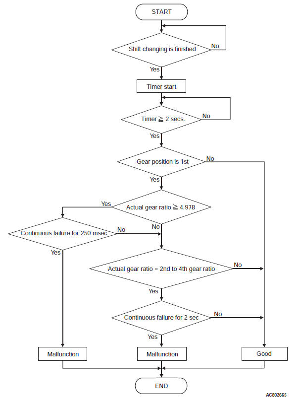
DTC SET CONDITIONS
Check Conditions
- Shift stage: 1st gear.
- Time after shift changing finish: 2 seconds or more.
Judgement Criteria
- Gear ratio: 4.978 or more. (0.25 second)
- Gear ratio: 2.114 or more and 2.584 or less. (2 seconds)
- Gear ratio: 1.392 or more and 1.701 or less. (2 seconds)
- Gear ratio: 1.021 or more and 1.247 or less. (2 seconds)
OBD-II DRIVE CYCLE PATTERN
1st gear driving for 5 seconds or more
TROUBLESHOOTING HINTS (THE MOST LIKELY CAUSES FOR THIS CODE TO BE SET ARE:)
- Transaxle assembly powertrain parts failure
- Malfunction of the P0715: input shaft speed sensor system
- Malfunction of the P0720: output shaft speed sensor system
- Malfunction of the P0748: line pressure linear solenoid valve system circuit
- Malfunction of the P0753: low clutch linear solenoid valve system circuit
- Malfunction of the P1758: low-reverse brake shift solenoid valve system circuit
- Malfunction of the low clutch
- Malfunction of the low one-way clutch
- Malfunction of the valve body assembly
DIAGNOSIS
STEP 1. Check the DTC.
Check that P0715 (input shaft speed sensor) and P0720 (output shaft speed sensor) are set.
Q: Is the DTC set?
YES : Check and repair the relevant DTC system.
NO : Go to Step 2.
STEP 2. Check the DTC.
Check if the DTC other than P0731 (1st gear ratio) is set.
Q: Is the DTC set?
YES : Check and repair the relevant DTC system.
NO : Go to Step 3.
STEP 3. Check the transmission fluid properties.
Check the status of the transmission fluid properties (smell, color, fouling).
- Black: A/T inside damage, seizure
- Milky: Water intrusion
Q: Is the check result normal?
YES : Go to Step 4.
NO : Remove the A/T from the vehicle, then check and repair the inside.
STEP 4. Check the transmission fluid level.
Q: Is the check result normal?
YES : Go to Step 5.
NO : Adjust the transmission fluid level, and then go to Step 5.
STEP 5. Check the signals of input shaft speed sensor and output shaft speed sensor.
Check the signals of C-37 TCM connector terminal No. 37 and No. 38.
Q: Is the check result normal?
YES : Go to Step 6.
NO : Repair or replace the failure section.
STEP 6. Hydraulic pressure test
Q: Is the check result normal?
YES : Go to Step 7.
NO : Remove the A/T from the vehicle, then check and repair the inside.
STEP 7. Erase the DTC code, and drive the vehicle for a while.
Check that the normal code is displayed.
Q: Is the check result normal?
YES : The procedure is complete.
NO : Return to START.
DTC P0736: Reverse Gear Incorrect Ratio
DESCRIPTIONS OF MONITOR METHODS
Check Conditions, Judgement Criteria
- During reverse driving, engine runup*1 is detected for 250 milliseconds or more.
*1: The actual gear ratio deviates from the target gear ratio to the high engine (turbine) speed.
MONITOR EXECUTION
- Reverse gear driving
MONITOR EXECUTION CONDITIONS (OTHER MONITOR AND SENSOR)
Other Monitor (There is no temporary DTC stored in memory for the item monitored below)
- P0846: Malfunction of the 2-6 brake pressure switch system
- P0876: Malfunction of the High clutch pressure switch system
- P0988: Malfunction of the Low-reverse brake pressure switch system
Sensor (The sensor below is determined to be normal)
- Not applicable
LOGIC FLOW CHARTS (Monitor Sequence)
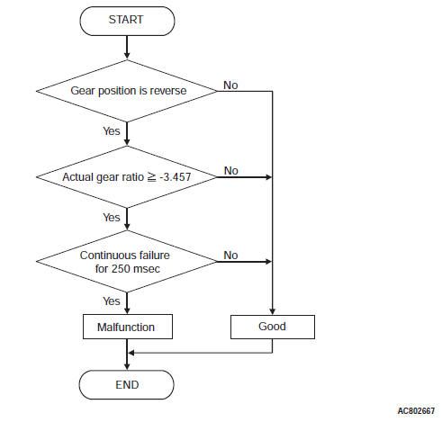
DTC SET CONDITIONS
Check Conditions
- Shift stage: reverse gear.
Judgement Criteria
- Gear ratio: more than -3.457. (0.25 second)
OBD-II DRIVE CYCLE PATTERN
Reverse gear driving for 5 seconds or more
TROUBLESHOOTING HINTS (THE MOST LIKELY CAUSES FOR THIS CODE TO BE SET ARE:)
- Transaxle assembly powertrain parts failure
- Malfunction of the P0715: input shaft speed sensor system
- Malfunction of the P0720: output shaft speed sensor system
- Malfunction of the P0748: line pressure linear solenoid valve system circuit
- Malfunction of the P0763: 3-5 reverse clutch linear solenoid valve system circuit
- Malfunction of the P0743: lock-up and low-reverse brake linear solenoid valve system circuit
- Malfunction of the P1758: low-reverse brake shift solenoid valve system circuit
- Malfunction of the 3-5 reverse clutch
- Malfunction of the low-reverse brake
- Malfunction of the valve body assembly
DIAGNOSIS
STEP 1. Check the DTC.
Check that P0715 (input shaft speed sensor) and P0720 (output shaft speed sensor) are set.
Q: Is the DTC set?
YES : Check and repair the relevant DTC system.
NO : Go to Step 2.
STEP 2. Check the DTC.
Check if the DTC other than P0736 (Reverse gear ratio) is set.
Q: Is the DTC set?
YES : Check and repair the relevant DTC system.
NO : Go to Step 3.
STEP 3. Check the transmission fluid properties.
Check the status of the transmission fluid properties (smell, color, fouling).
- Black: A/T inside damage, seizure
- Milky: Water intrusion
Q: Is the check result normal?
YES : Go to Step 4.
NO : Remove the A/T from the vehicle, then check and repair the inside.
STEP 4. Check the transmission fluid level.
Q: Is the check result normal?
YES : Adjust the transmission fluid level, and then go to Step 5.
NO : Go to Step 5.
STEP 5. Check the signals of input shaft speed sensor and output shaft speed sensor.
Check the signals of C-37 TCM connector terminal No. 37 and No. 38.
Q: Is the check result normal?
YES : Go to Step 6.
NO : Repair or replace the failure section.
STEP 6. Hydraulic pressure test
Q: Is the check result normal?
YES : Go to Step 7.
NO : Remove the A/T from the vehicle, then check and repair the inside.
STEP 7. Erase the DTC code, and drive the vehicle for a while.
Check that the normal code is displayed.
Q: Is the check result normal?
YES : The procedure is complete.
NO : Return to START.
READ NEXT:
 DTC P0741, P0742, P0743, P0748, P0753, P0758, P0763, P0768, P0815,
P0816, P0826, P0846
DTC P0741, P0742, P0743, P0748, P0753, P0758, P0763, P0768, P0815,
P0816, P0826, P0846
DTC P0741: Torque Converter Clutch System (Stuck Off), P0742 Torque
Converter Clutch System
(Stuck ON)
DESCRIPTIONS OF MONITOR METHODS
<P0741>
When the input shaft speed sensor is normal, the
DTC P0876, P0893, P0988, P1705, P1706, P1731, P1753, P1758, P1773,
P1796, U0001, U0100, U0121, U0141
DTC P0876: High Clutch Pressure Switch System
DESCRIPTIONS OF MONITOR METHODS
With the solenoid failure not detected and with
4th to 6th gear driving, the switch OFF status
continues for 2 seconds
Inspection Procedure
INSPECTION PROCEDURE 1: The vehicle does not run at any range
(including low power).
TROUBLESHOOTING HINTS (THE MOST
LIKELY CAUSES FOR THIS CONDITION:)
Malfunction of the engine
Insufficient trans
SEE MORE:
Rear Wiper and Washer
GENERAL INFORMATION
REAR WIPER AND WASHER
REAR WIPER OPERATION
If the rear wiper and washer switch is turned to
the "INT" position with the ignition switch at
"ACC" or "ON" position, the ETACS-ECU causes
the rear wiper to operate continuously 2 times,
then intermittently at 8-second intervals
Engine Cooling Diagnosis
INTRODUCTION
The system cools the engine so that it does not overheat
and maintains the engine at an optimum temperature.
The system components are the radiator,
water pump, thermostat, condenser fan assembly.
Possible faults include low coolant, contamination,
belt loosening and component damage
