Mitsubishi Outlander: Diagnosis S-AWC (Super All Wheel Control)
TROUBLESHOOTING STRATEGY
Refer to GROUP 00 − How to Use Troubleshooting/ Inspection Service Points.
PRECAUTIONS FOR DIAGNOSIS
Before diagnosis, check that all the following items are normal.
- A normal steering wheel is installed correctly to the neutral position of steering column shaft assembly.
- The size of tire and wheel, specification, tire pressure, balance, and wear status are normal.
- The wheel alignment is normal.
- No modifications to the engine, suspension, or others, which can affect the S-AWC system, is implemented.
DIAGNOSIS FUNCTION
WARNING INDICATOR
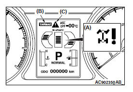
When a malfunction occurs in the S-AWC system, the figure (A) will be displayed on the information screen of multi information display, and the mode display (B) will be turned off.
Subsequently, the screen returns to the one before the warning display, and then "!" indicator (C) will illuminate.
If the indicator (C) continues to be displayed on the information screen of multi information display, check the diagnostic trouble code that is set.
FAIL-SAFE FUNCTION
If an abnormality occurs to the signal of sensors, switches, solenoids, or others, the AWC-ECU performs a control for the driver safety and system protection.
The control contents are as follows.
FAIL-SAFE REFERENCE TABLE
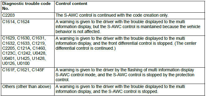
NOTE: All the fail-safe functions are reset by turning OFF → ON the ignition switch.
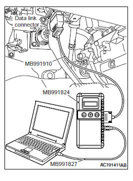
HOW TO CONNECT THE SCAN TOOL (M.U.T.-III)
Required Special Tools:
- MB991958: Scan Tool (M.U.T.-III Sub Assembly)
- MB991824: Vehicle Communication Interface (V.C.I.)
- MB991827: M.U.T.-III USB Cable
- MB991910: M.U.T.-III Main Harness A
CAUTION To prevent damage to scan tool MB991958, always turn the ignition switch to the "LOCK" (OFF) position before connecting or disconnecting scan tool MB991958.
1. Ensure that the ignition switch is at the "LOCK" (OFF) position.
2. Start up the personal computer.
3. Connect special tool MB991827 to special tool MB991824 and the personal computer.
4. Connect special tool MB991910 to special tool MB991824.
5. Connect special tool MB991910 to the data link connector.
6. Turn the power switch of special tool MB991824 to the "ON" position.
NOTE: When special tool MB991824 is energized, special tool MB991824 indicator light will be illuminated in a green color.
7. Start the M.U.T.-III system on the personal computer.
NOTE: Disconnecting scan tool MB991958 is the reverse of the connecting sequence, making sure that the ignition switch is at the "LOCK" (OFF) position.
CHECK OF THE FREEZE FRAME DATA
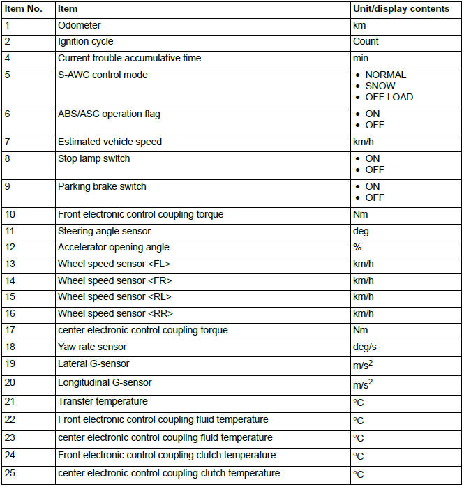
Various data of when the diagnostic trouble code has been set is obtained, and the status of that time is stored. By analyzing each data using M.U.T.-III, troubleshooting can be carried out efficiently.
Display items of the freeze frame data are as follows.
DISPLAY ITEM LIST
CHECK CHART FOR DIAGNOSTIC TROUBLE CODE
CAUTION During diagnosis, a diagnostic trouble code associated with other system may be set when the ignition switch is turned ON with connector(s) disconnected. On completion, confirm all systems for diagnostic trouble code(s). If diagnostic trouble code(s) are set, erase them all.
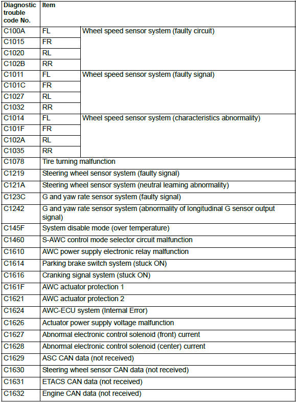
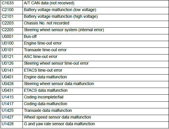
SYMPTOM CHART
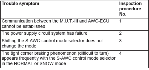
- DTC No.C100A, C1015, C1020, C102B, C1011, C101C, C1027, C1032, C1014, C101F, C102A, C1035, C1078, C1219, C121A, C123C, C1242, C145F, C1460, C1610, C1614, C1616
- DTC No.C161F, C1621, C1624, C1626, C1627, C1628, C1629, C1630, C1631, C1632, C1633, C2100, C2101, C2203, C2205
- DTC No.U0001, U0100, U0101, U0121, U0126, U0141, U0401, U0428, U0431, U1415, U1417, U1425, U1427, U1428
- Inspection Procedure

