Mitsubishi Outlander: DTC No.C161F, C1621, C1624, C1626, C1627, C1628, C1629, C1630, C1631, C1632, C1633, C2100, C2101, C2203, C2205
Code No.C161F: AWC actuator protection 1
CAUTION
- If there is any problem in the CAN bus lines, an incorrect diagnostic trouble code may be set. Prior to this diagnosis, diagnose the CAN bus lines.
- Whenever the ECU is replaced, ensure that the CAN bus lines are normal.
OPERATION
The AWC-ECU calculates the electronic control coupling (front) temperature by the information of the electronic control coupling (front) control amount, outside temperate, etc. If it is detected that the electronic control coupling (Front) temperature becomes extremely high, the high fluid temperature warning is displayed on the warning indicator.
DIAGNOSTIC TROUBLE CODE SET CONDITIONS
This diagnostic trouble code is set when the control is suspended to protect the electronic control coupling (front).
PROBABLE CAUSES
- Electronic control coupling (front) protection control status
- Severe driving
- Electronic control coupling (front) failure (clutch slippage, etc.)
- Outside temperature signal failure
- Wheel speed signal failure
- Engine-related failure (engine speed signal failure)
- Ignition off time signal failure
DIAGNOSTIC PROCEDURE
STEP 1. Check whether the diagnostic trouble code is reset.
- To release the electronic control coupling (front) protection control, leave the vehicle for 15 minutes or longer after the high fluid temperature warning on the warning indicator disappears.
- Erase the diagnostic trouble code.
- Carry out the test drive.
NOTE: Do not carry out the severe test drive.
- Check if the diagnostic trouble code is set.
Q: Is diagnostic trouble code No.C161F set? YES : Go to Step 2.
NO : This diagnosis is complete.
STEP 2. M.U.T.-III CAN bus diagnostics.
Use scan tool to perform the CAN bus diagnosis.
Q: Is the check result normal?
YES : Go to Step 4.
NO : Repair the CAN bus lines. After repairing the CAN bus line, go to Step 3.
STEP 3. Check whether the diagnostic trouble code is reset.
Q: Is diagnostic trouble code No.C161F set? YES : Go to Step 4.
NO : This diagnosis is complete.
STEP 4. M.U.T.-III data list
Item 12: Engine speed.
Q: Is the check result normal?
YES : Go to Step 5.
NO : Perform the troubleshooting for the engine control system.
STEP 5. M.U.T.-III data list
Check the following data list.
- Item No.21: Wheel speed sensor <FL>
- Item No.22: Wheel speed sensor <FR>
- Item No.23: Wheel speed sensor <RL>
- Item No.24: Wheel speed sensor <RR>
Q: Is the check result normal?
YES : Go to Step 6.
NO : Perform the troubleshooting for the ASC.
STEP 6. M.U.T.-III data list
Check the following data list.
- Item No.34: Ambient temperature (CAN input)
- Item No.35: Ignition off time (CAN input)
Q: Is the check result normal?
YES : Go to Step 7.
NO : Perform the troubleshooting for the ETACS.
STEP 7. Check of the electronic control coupling (Front)
Q: Is the check result normal?
YES : Go to Step 8.
NO : Replace the transfer assembly.
STEP 8. Check whether the diagnostic trouble code is reset.
- To release the electronic control coupling (front) protection control, leave the vehicle for 15 minutes or longer after the high fluid temperature warning on the warning indicator disappears.
- Erase the diagnostic trouble code.
- Carry out the test drive.
NOTE: Do not carry out the severe test drive.
- Check if the diagnostic trouble code is set.
Q: Is diagnostic trouble code No.C161F set? YES : Replace the AWC-ECU.
NO : Intermittent malfunction.
Code No.C1621: AWC actuator protection 2
CAUTION
- If there is any problem in the CAN bus lines, an incorrect diagnostic trouble code may be set. Prior to this diagnosis, diagnose the CAN bus lines.
- Whenever the ECU is replaced, ensure that the CAN bus lines are normal.
OPERATION
The AWC-ECU calculates the electronic control coupling (center) temperature by the information of the electronic control coupling (center) control amount, outside temperate, etc. If it is detected that the electronic control coupling (center) temperature becomes extremely high, the high fluid temperature warning is displayed on the warning indicator.
DIAGNOSTIC TROUBLE CODE SET CONDITIONS
This diagnostic trouble code is set when the control is suspended to protect the electronic control coupling (center).
PROBABLE CAUSES
- Electronic control coupling (center) protection control status
- Severe driving
- Electronic control coupling (center) failure (clutch slippage, etc.)
- Outside temperature signal failure
- Wheel speed signal failure
- Engine-related failure (engine speed signal failure)
- Ignition off time signal failure
DIAGNOSTIC PROCEDURE
STEP 1. Check whether the diagnostic trouble code is reset.
- To release the electronic control coupling (center) protection control, leave the vehicle for 15 minutes or longer after the high fluid temperature warning on the warning indicator disappears.
- Erase the diagnostic trouble code.
- Carry out the test drive.
NOTE: Do not carry out the severe test drive.
- Check if the diagnostic trouble code is set.
Q: Is diagnostic trouble code No.C1621 set? YES : Go to Step 2.
NO : This diagnosis is complete.
STEP 2. M.U.T.-III CAN bus diagnostics.
Use scan tool to perform the CAN bus diagnosis.
Q: Is the check result normal?
YES : Go to Step 4.
NO : Repair the CAN bus lines. After repairing the CAN bus line, go to Step 3.
STEP 3. Check whether the diagnostic trouble code is reset.
Q: Is diagnostic trouble code No.C1621 set? YES : Go to Step 4.
NO : This diagnosis is complete.
STEP 4. M.U.T.-III data list
Item 12: Engine speed.
Q: Is the check result normal?
YES : Go to Step 5.
NO : Perform the troubleshooting for the engine.
STEP 5. M.U.T.-III data list
Check the following data list.
- Item No.21: Wheel speed sensor <FL>
- Item No.22: Wheel speed sensor <FR>
- Item No.23: Wheel speed sensor <RL>
- Item No.24: Wheel speed sensor <RR>
Q: Is the check result normal?
YES : Go to Step 6.
NO : Perform the troubleshooting for the ASC.
STEP 6. M.U.T.-III data list
Check the following data list.
- Item No.34: Ambient temperature (CAN input)
- Item No.35: Ignition off time (CAN input)
Q: Is the check result normal?
YES : Go to Step 7.
NO : Perform the troubleshooting for the ETACS.
STEP 7. Check of the electronic control coupling (center)
Q: Is the check result normal?
YES : Go to Step 8.
NO : Replace the electronic control coupling (center).
STEP 8. Check whether the diagnostic trouble code is reset.
- To release the electronic control coupling (center) protection control, leave the vehicle for 15 minutes or longer after the high fluid temperature warning on the warning indicator disappears.
- Erase the diagnostic trouble code.
- Carry out the test drive.
NOTE: Do not carry out the severe test drive.
- Check if the diagnostic trouble code is set.
Q: Is diagnostic trouble code No.C161F set? YES : Replace the AWC-ECU.
NO : Intermittent malfunction.
Code No.C1624: AWC-ECU System (Internal Error)
OPERATION
AWC-ECU monitors the malfunction in the ECU.
DIAGNOSTIC TROUBLE CODE SET CONDITIONS
This diagnostic trouble code is set when RAM/ROM/EEPROM of AWC-ECU has a failure.
PROBABLE CAUSES
- Malfunction of AWC-ECU
DIAGNOSTIC PROCEDURE
STEP 1. Check whether the diagnostic trouble code is reset.
Q: Is diagnostic trouble code No.C1624 set? YES : Replace the AWC-ECU. Then go to Step 2.
NO : Intermittent malfunction.
STEP 2. Check whether the diagnostic trouble code is reset.
Q: Is diagnostic trouble code No.C1624 set? YES : Return to Step 1.
NO : This diagnosis is complete.
Code No. C1626: Actuator Power Supply Voltage Malfunction
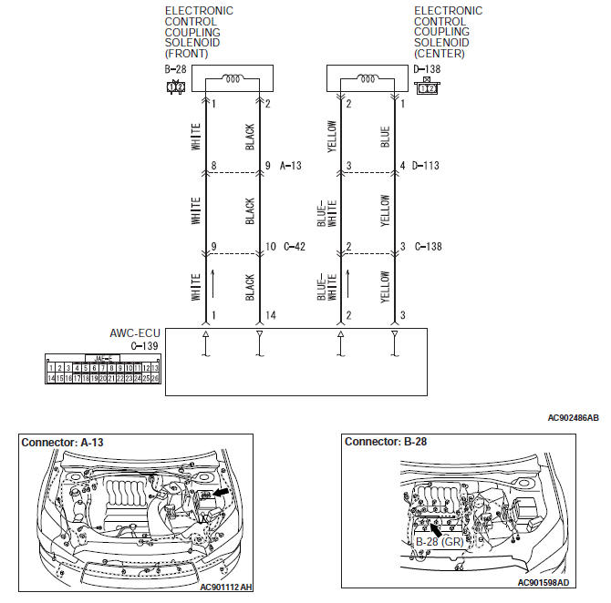
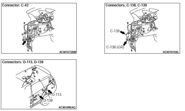
Electronic control coupling solenoid system circuit
OPERATION
The AWC-ECU monitors the actuator power supply voltage.
DIAGNOSTIC TROUBLE CODE SET CONDITIONS
The AWC-ECU monitors the actuator power supply voltage of immediately after the ignition is turned ON and when the abnormality of the actuator power supply voltage is detected, this diagnostic trouble code is set.
PROBABLE CAUSES
- Malfunction of electronic control coupling solenoid (center)
- Malfunction of electronic control coupling solenoid (Front)
- Damaged harness wires and connectors
- Malfunction of AWC-ECU
DIAGNOSTIC PROCEDURE
STEP 1. Electronic control coupling solenoid (front) connector, intermediate connector, AWC-ECU connector check: B-28, A-13, C-42, C-139
Q: Is the check result normal?
YES : Go to Step 2.
NO : Repair the defective connector. Then go to Step 10.
STEP 2. Check the wiring harness between B-28 electronic control coupling solenoid (front) connector terminal No.1 and C-139 AWC-ECU connector terminal No.1.
Check the power supply line for short circuit (for short to the power supply).
Q: Is the check result normal?
YES : Go to Step 3.
NO : Repair the wiring harness. Then go to Step 10.
STEP 3. Check the wiring harness between B-28 electronic control coupling solenoid (front) connector terminal No.2 and C-139 AWC-ECU connector terminal No.14.
Check the ground line for short circuit (for short to the power supply).
Q: Is the check result normal?
YES : Go to Step 4.
NO : Repair the wiring harness. Then go to Step 10.
STEP 4. Check of the electronic control coupling solenoid (Front)
Q: Is the check result normal?
YES : Go to Step 5.
NO : Replace the transfer assembly.
Then go to Step 10.
STEP 5. Electronic control coupling solenoid (center) connector, intermediate connector, AWC-ECU connector check: D-138, C-138, D-113, C-139
Q: Is the check result normal?
YES : Go to Step 6.
NO : Repair the defective connector. Then go to Step 10.
STEP 6. Check the wiring harness between D-138 electronic control coupling solenoid (center) connector terminal No.2 and C-139 AWC-ECU connector terminal No.2.
Check the power supply line for short circuit (for short to the power supply).
Q: Is the check result normal?
YES : Go to Step 7.
NO : Repair the wiring harness. Then go to Step 10.
STEP 7. Check the wiring harness between D-138 electronic control coupling solenoid (center) connector terminal No.1 and C-139 AWC-ECU connector terminal No.3.
Check the ground line for short circuit (for short to the power supply).
Q: Is the check result normal?
YES : Go to Step 8.
NO : Repair the wiring harness. Then go to Step 10.
STEP 8. Check of the electronic control coupling solenoid (center)
Q: Is the check result normal?
YES : Go to Step 9.
NO : Replace the electronic control coupling (center).
STEP 9. Check whether the diagnostic trouble code is reset.
Q: Is diagnostic trouble code No.C1626 set? YES : Replace the AWC-ECU. Then go to Step 10.
NO : Intermittent malfunction.
STEP 10. Check whether the diagnostic trouble code is reset.
Q: Is diagnostic trouble code No.C1626 set? YES : Return to Step 1.
NO : This diagnosis is complete.
Code No. C1627: Abnormal Electronic Control Solenoid (Front) Current
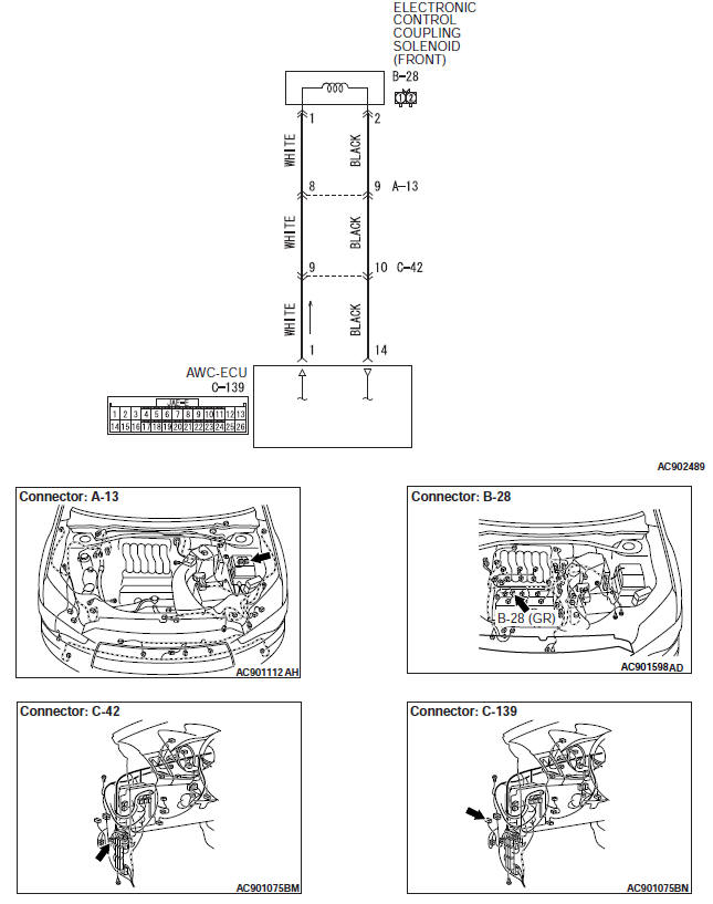
Electronic control coupling solenoid (front) system circuit
OPERATION
The AWC-ECU monitors the current value of the electronic control coupling solenoid (Front).
DIAGNOSTIC TROUBLE CODE SET CONDITIONS
This diagnostic trouble code is set when the abnormality below is detected:
- By the monitored electronic control solenoid (front) current, the AWC-ECU judges the undercurrent failure.
- By the monitored electronic control solenoid (front) current, the AWC-ECU judges the overcurrent failure.
- The AWC-ECU judges the monitor circuit failure.
PROBABLE CAUSES
- Malfunction of electronic control coupling solenoid (Front)
- Damaged harness wires and connectors
- Malfunction of AWC-ECU
DIAGNOSTIC PROCEDURE
STEP 1. Electronic control coupling solenoid (front) connector, intermediate connector, AWC-ECU connector check: B-28, A-13, C-42, C-139
Q: Is the check result normal?
YES : Go to Step 2.
NO : Repair the defective connector. Then go to Step 6.
STEP 2. Check the wiring harness between B-28 electronic control coupling solenoid (front) connector terminal No.1 and C-139 AWC-ECU connector terminal No.1.
Check the power supply line for open or short circuit.
Q: Is the check result normal?
YES : Go to Step 3.
NO : Repair the wiring harness. Then go to Step 6.
STEP 3. Check the wiring harness between B-28 electronic control coupling solenoid (front) connector terminal No.2 and C-139 AWC-ECU connector terminal No.14.
Check the ground line for open or short circuit.
Q: Is the check result normal?
YES : Go to Step 4.
NO : Repair the wiring harness. Then go to Step 6.
STEP 4. Check of the electronic control coupling solenoid (Front)
Q: Is the check result normal?
YES : Go to Step 5.
NO : Replace the transfer assembly.
Then go to Step 6.
STEP 5. Check whether the diagnostic trouble code is reset.
Q: Is diagnostic trouble code No.C1627 set? YES : Replace the AWC-ECU. Then go to Step 6.
NO : Intermittent malfunction.
STEP 6. Check whether the diagnostic trouble code is reset.
Q: Is diagnostic trouble code No.C1627 set? YES : Return to Step 1.
NO : This diagnosis is complete.
Code No. C1628: Abnormal Electronic Control Solenoid (center) Current
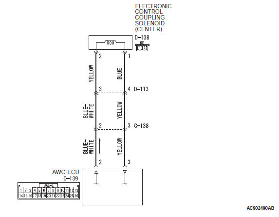
Electronic control coupling solenoid (rear) system circuit

OPERATION
The AWC-ECU monitors the current value of the electronic control coupling solenoid (center).
DIAGNOSTIC TROUBLE CODE SET CONDITIONS
This diagnostic trouble code is set when the abnormality below is detected:
- By the monitored electronic control solenoid (center) current, the AWC-ECU judges the undercurrent failure.
- By the monitored electronic control solenoid (center) current, the AWC-ECU judges the overcurrent failure.
- The AWC-ECU judges the monitor circuit failure.
PROBABLE CAUSES
- Malfunction of electronic control coupling solenoid (center)
- Damaged harness wires and connectors
- Malfunction of AWC-ECU
DIAGNOSTIC PROCEDURE
STEP 1. Electronic control coupling solenoid (center) connector, intermediate connector, AWC-ECU connector check: D-138, C-138, D-113, C-139
Q: Is the check result normal?
YES : Go to Step 2.
NO : Repair the defective connector. Then go to Step 6.
STEP 2. Check the wiring harness between D-138 electronic control coupling solenoid (center) connector terminal No.2 and C-139 AWC-ECU connector terminal No.2.
Check the power supply line for open or short circuit.
Q: Is the check result normal?
YES : Go to Step 3.
NO : Repair the wiring harness. Then go to Step 6.
STEP 3. Check the wiring harness between D-138 electronic control coupling solenoid (center) connector terminal No.1 and C-139 AWC-ECU connector terminal No.3.
Check the ground line for open or short circuit.
Q: Is the check result normal?
YES : Go to Step 4.
NO : Repair the wiring harness. Then go to Step 6.
STEP 4. Check of the electronic control coupling solenoid (center)
Q: Is the check result normal?
YES : Go to Step 5.
NO : Replace the electronic control coupling (center). Then go to Step 6.
STEP 5. Check whether the diagnostic trouble code is reset.
Q: Is diagnostic trouble code No.C1628 set? YES : Replace the AWC-ECU. Then go to Step 6.
NO : Intermittent malfunction.
STEP 6. Check whether the diagnostic trouble code is reset.
Q: Is diagnostic trouble code No.C1628 set? YES : Return to Step 1.
NO : This diagnosis is complete.
Code No. C1629: ASC CAN Data (not received)
CAUTION
- If there is any problem in the CAN bus lines, an incorrect diagnostic trouble code may be set. Prior to this diagnosis, diagnose the CAN bus lines.
- Whenever the ECU is replaced, ensure that the CAN bus lines are normal.
OPERATION
AWC-ECU communicates with the ASC-ECU via the CAN bus lines.
DIAGNOSTIC TROUBLE CODE SET CONDITIONS
This diagnostic trouble code is set when the CAN signal of the ASC-ECU cannot be received.
PROBABLE CAUSES
- Malfunction of the CAN bus line
- Damaged connectors (ASC-ECU)
- Malfunction of ASC-ECU
- Malfunction of AWC-ECU
DIAGNOSTIC PROCEDURE
STEP 1. M.U.T.-III CAN bus diagnostics.
Use scan tool to perform the CAN bus diagnosis.
Q: Is the check result normal?
YES : Go to Step 2.
NO : Repair the CAN bus lines.
STEP 2. M.U.T.-III diagnostic trouble code.
Check the ASC diagnostic trouble code. (Refer to GROUP 35C − Troubleshooting).
Q: Is the diagnostic trouble code set? YES : Perform the relevant troubleshooting.
NO : Go to Step 3.
STEP 3. Check whether the diagnostic trouble code is reset.
Q: Is diagnostic trouble code No.C1629 set? YES : Replace the AWC-ECU. Then go to Step 4.
NO : Intermittent malfunction.
STEP 4. Check whether the diagnostic trouble code is reset.
Q: Is diagnostic trouble code No.C1629 set? YES : Return to Step 1.
NO : This diagnosis is complete.
Code No. C1630: Steering Wheel Sensor CAN Data (not received)
CAUTION
- If there is any problem in the CAN bus lines, an incorrect diagnostic trouble code may be set. Prior to this diagnosis, diagnose the CAN bus lines.
- Whenever the ECU is replaced, ensure that the CAN bus lines are normal.
- When the steering wheel sensor is replaced, calibrate the steering wheel sensor (Refer to GROUP 35C − On-vehicle Service), and reset the steering wheel sensor correction amount stored in the AWC-ECU. (Item No.1: SAS adjusted value).
OPERATION
AWC-ECU communicates with the steering wheel sensor via the CAN bus lines.
DIAGNOSTIC TROUBLE CODE SET CONDITIONS
This diagnostic trouble code is set when the CAN signal of the steering wheel sensor cannot be received.
PROBABLE CAUSES
- Malfunction of the CAN bus line
- Damaged connectors (steering wheel sensor)
- Malfunction of the steering wheel sensor
- Malfunction of AWC-ECU
DIAGNOSTIC PROCEDURE
STEP 1. M.U.T.-III CAN bus diagnostics.
Use scan tool to perform the CAN bus diagnosis.
Q: Is the check result normal?
YES : Go to Step 2.
NO : Repair the CAN bus lines.
STEP 2. M.U.T.-III data list.
Item No.8: Steering angle sensor.
Q: Is the check result normal?
YES : Intermittent malfunction.
NO : Replace the steering wheel sensor. Then go to Step 3.
STEP 3. Check whether the diagnostic trouble code is reset.
Q: Is diagnostic trouble code No.C1630 set? YES : Replace the AWC-ECU. Then go to Step 4.
NO : Intermittent malfunction.
STEP 4. Check whether the diagnostic trouble code is reset.
Q: Is diagnostic trouble code No.C1630 set? YES : Return to Step 1.
NO : This diagnosis is complete.
Code No. C1631: ETACS CAN Data (not received)
CAUTION
- If there is any problem in the CAN bus lines, an incorrect diagnostic trouble code may be set. Prior to this diagnosis, diagnose the CAN bus lines.
- Whenever the ECU is replaced, ensure that the CAN bus lines are normal.
OPERATION
AWC-ECU communicates with the ETACS-ECU via the CAN bus lines.
DIAGNOSTIC TROUBLE CODE SET CONDITIONS
This diagnostic trouble code is set when the CAN signal of the ETACS-ECU cannot be received.
PROBABLE CAUSES
- Malfunction of the CAN bus line
- Damaged connectors (ETACS-ECU)
- ETACS-ECU malfunction
- Malfunction of AWC-ECU
DIAGNOSTIC PROCEDURE
STEP 1. M.U.T.-III CAN bus diagnostics.
Use scan tool to perform the CAN bus diagnosis.
Q: Is the check result normal?
YES : Go to Step 2.
NO : Repair the CAN bus lines.
STEP 2. M.U.T.-III diagnostic trouble code.
Check the ETACS diagnostic trouble code.
Q: Is the diagnostic trouble code set? YES : Perform the relevant troubleshooting.
NO : Go to Step 3.
STEP 3. Check whether the diagnostic trouble code is reset.
Q: Is diagnostic trouble code No.C1631 set? YES : Replace the AWC-ECU. Then go to Step 4.
NO : Intermittent malfunction.
STEP 4. Check whether the diagnostic trouble code is reset.
Q: Is diagnostic trouble code No.C1631 set? YES : Return to Step 1.
NO : This diagnosis is complete.
Code No. C1632: Engine CAN Data (not received)
CAUTION
- If there is any problem in the CAN bus lines, an incorrect diagnostic trouble code may be set. Prior to this diagnosis, diagnose the CAN bus lines.
- Whenever the ECU is replaced, ensure that the CAN bus lines are normal.
OPERATION
AWC-ECU communicates with the engine control module via the CAN bus lines.
DIAGNOSTIC TROUBLE CODE SET CONDITIONS
This diagnostic trouble code is set when the CAN signal of the engine control module cannot be received.
PROBABLE CAUSES
- Malfunction of the CAN bus line
- Damaged connectors (Engine control module)
- Malfunction of engine control module
- Malfunction of AWC-ECU
DIAGNOSTIC PROCEDURE
STEP 1. M.U.T.-III CAN bus diagnostics.
Use scan tool to perform the CAN bus diagnosis.
Q: Is the check result normal?
YES : Go to Step 2.
NO : Repair the CAN bus lines. After repairing the CAN bus line, go to Step 2.
STEP 2. M.U.T.-III diagnostic trouble code.
Check the engine diagnostic trouble code.
Q: Is the diagnostic trouble code set? YES : Perform the relevant troubleshooting.
NO : Go to Step 3.
STEP 3. Check whether the diagnostic trouble code is reset.
Q: Is diagnostic trouble code No.C1632 set? YES : Replace the AWC-ECU. Then go to Step 4.
NO : Intermittent malfunction.
STEP 4. Check whether the diagnostic trouble code is reset.
Q: Is diagnostic trouble code No.C1632 set? YES : Return to Step 1.
NO : This diagnosis is complete.
Code No. C1633: A/T CAN Data (not received)
CAUTION
- If there is any problem in the CAN bus lines, an incorrect diagnostic trouble code may be set. Prior to this diagnosis, diagnose the CAN bus lines.
- Whenever the ECU is replaced, ensure that the CAN bus lines are normal.
OPERATION
AWC-ECU communicates with A/T-ECU via the CAN bus lines.
DIAGNOSTIC TROUBLE CODE SET CONDITIONS
This diagnostic trouble code is set when the CAN signal of the A/T-ECU cannot be received.
PROBABLE CAUSES
- Malfunction of the CAN bus line
- Damaged connectors (A/T-ECU)
- Malfunction of A/T-ECU
- Malfunction of AWC-ECU
- Coding failure (installation of M/T for a vehicle with A/T specification, failure coding of A/T for a vehicle with M/T specification)
DIAGNOSTIC PROCEDURE
STEP 1. M.U.T.-III CAN bus diagnostics.
Use scan tool to perform the CAN bus diagnosis.
Q: Is the check result normal?
YES : Go to Step 2.
NO : Repair the CAN bus lines.
STEP 2. M.U.T.-III diagnostic trouble code.
Check the A/T diagnostic trouble code.
Q: Is the diagnostic trouble code set? YES : Perform the relevant troubleshooting.
NO : Go to Step 3.
STEP 3. ETACS-ECU coding data check.
Check the Transaxle coding data stored in ETACS-ECU for any abnormality.
Q: Is the check result normal?
YES : Go to Step 4.
NO : Replace the ETACS-ECU. Then go to Step 5.
STEP 4. Check whether the diagnostic trouble code is reset.
Q: Is diagnostic trouble code No.U0101 set? YES : Replace the AWC-ECU. Then go to Step 5.
NO : Intermittent malfunction.
STEP 5. Check whether the diagnostic trouble code is reset.
Q: Is diagnostic trouble code No.U0101 set? YES : Return to Step 1.
NO : This diagnosis is complete.
Code No.C2100: Battery Voltage Malfunction (Low Voltage)
Power supply system circuit
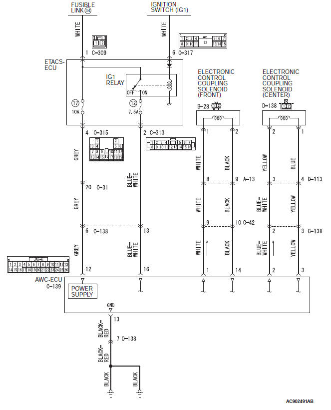
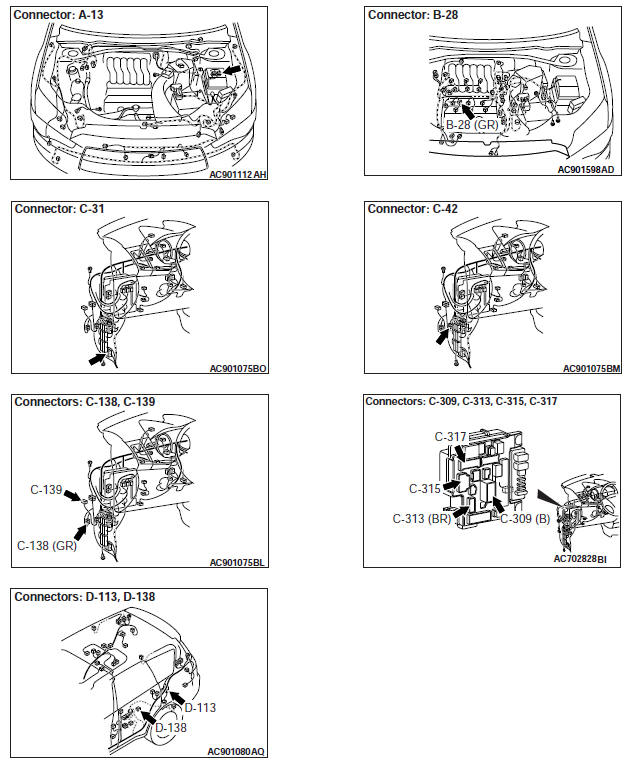
OPERATION
AWC-ECU power supply is provided from the battery via ETACS-ECU.
DIAGNOSTIC TROUBLE CODE SET CONDITIONS
This diagnostic trouble code is set when the AWC-ECU power supply voltage and the actuator power supply voltage are less than 9 V.
PROBABLE CAUSES
- Battery failure
- Malfunction of charging system
- Malfunction of ETACS-ECU (power supply circuit system)
- Damaged harness wires and connectors
- Malfunction of electronic control coupling solenoid (Front)
- Malfunction of electronic control coupling solenoid (center)
- Malfunction of AWC-ECU
DIAGNOSTIC PROCEDURE
STEP 1. M.U.T.-III diagnostic trouble code.
Check the ETACS diagnostic trouble code.
Q: Is the diagnostic trouble code set? YES : Perform the relevant troubleshooting.
NO : Go to Step 2.
STEP 2. Check the battery.
Q: Is the check result normal?
YES : Go to Step 4.
NO : Charge or replace the battery. Then go to Step 3.
STEP 3. Check the charging system.
Q: Is the check result normal?
YES : Go to Step 4.
NO : Repair or replace the charging system component(s).
STEP 4. Voltage measurement at C-139 AWC-ECU connector
Disconnect the connector, and measure the voltage between terminal No.12 and ground at the wiring harness side.
OK: Battery positive voltage Q: Is the check result normal? YES : Go to Step 8.
NO : Go to Step 5.
STEP 5. AWC-ECU connector, ETACS-ECU connector check: C-139, C-315, C-138, C-31
Q: Is the check result normal?
YES : Go to Step 6.
NO : Repair the defective connector. Then go to Step 19.
STEP 6. Check the wiring harness between C-139 AWC-ECU connector terminal No.12 and C-315 ETACS-ECU connector terminal No.4.
Check the power supply line for short or open circuit.
Q: Is the check result normal?
YES : Go to Step 7.
NO : Check C-31, C-138 intermediate connector. When no problem is found, repair the wiring harness. Then go to Step 19.
STEP 7. M.U.T.-III data list.
Item No.31: Battery voltage (CAN input).
Q: Is the check result normal?
YES : Intermittent malfunction.
NO : Replace the ETACS-ECU. Then go to Step 19.
STEP 8. AWC-ECU connector check: C-138, C-139
Q: Is the check result normal?
YES : Go to Step 9.
NO : Repair the defective connector. Then go to Step 19.
STEP 9. Check the wiring harness between C-139 AWC-ECU connector terminal No.13 and body ground.
Check the ground line for open circuit.
Q: Is the check result normal?
YES : Go to Step 10.
NO : Repair the wiring harness. Then go to Step 19.
STEP 10. Electronic control coupling solenoid (front) connector, intermediate connector, AWC-ECU connector check: B-28, A-13, C-42, C-139
Q: Is the check result normal?
YES : Go to Step 11.
NO : Repair the defective connector. Then go to Step 19.
STEP 11. Check the wiring harness between B-28 electronic control coupling solenoid (front) connector terminal No.1 and C-139 AWC-ECU connector terminal No.1.
Check the power supply line for short circuit.
Q: Is the check result normal?
YES : Go to Step 12.
NO : Repair the wiring harness. Then go to Step 19.
STEP 12. Check the wiring harness between B-28 electronic control coupling solenoid (front) connector terminal No.2 and C-139 AWC-ECU connector terminal No.14.
Check the ground line for short circuit.
Q: Is the check result normal?
YES : Go to Step 13.
NO : Repair the wiring harness. Then go to Step 19.
STEP 13. Check of the electronic control coupling solenoid (Front)
Q: Is the check result normal?
YES : Go to Step 14.
NO : Replace the transfer assembly.
Then go to Step 19.
STEP 14. Electronic control coupling solenoid (center) connector, intermediate connector, AWC-ECU connector check: D-138, C-138, D-113, C-139
Q: Is the check result normal?
YES : Go to Step 15.
NO : Repair the defective connector. Then go to Step 19.
STEP 15. Check the wiring harness between D-138 electronic control coupling solenoid (center) connector terminal No.2 and C-139 AWC-ECU connector terminal No.2.
Check the power supply line for short circuit.
Q: Is the check result normal?
YES : Go to Step 16.
NO : Repair the wiring harness. Then go to Step 19.
STEP 16. Check the wiring harness between D-138 electronic control coupling solenoid (center) connector terminal No.1 and C-139 AWC-ECU connector terminal No.3.
Check the ground line for short circuit.
Q: Is the check result normal?
YES : Go to Step 17.
NO : Repair the wiring harness. Then go to Step 19.
STEP 17. Check of the electronic control coupling solenoid (center)
Q: Is the check result normal?
YES : Go to Step 18.
NO : Replace the electronic control coupling (center). Then go to Step 19.
STEP 18. M.U.T.-III data list.
Item No.31: Battery voltage (CAN input).
Q: Is the check result normal?
YES : Intermittent malfunction.
NO : Replace the AWC-ECU. Then go to Step 19.
STEP 19. Check whether the diagnostic trouble code is reset.
Q: Is diagnostic trouble code No.C2100 set? YES : Return to Step 1.
NO : This diagnosis is complete.
Code No.C2101: Battery Voltage Malfunction (High Voltage)
Power supply system circuit
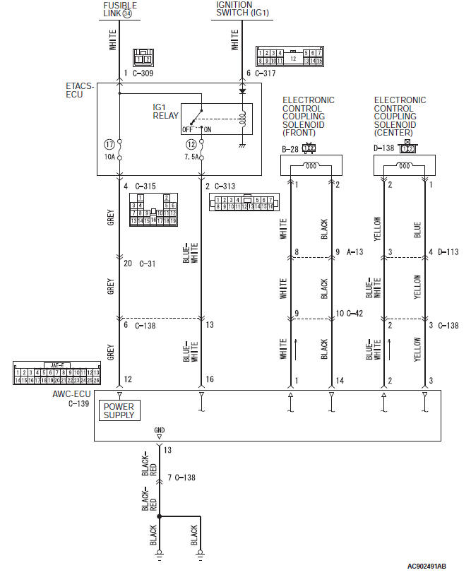
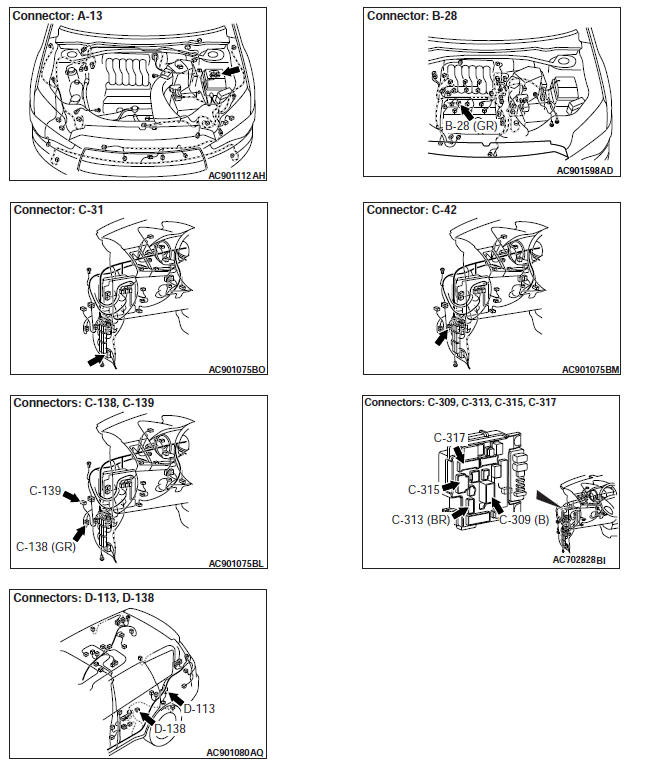
OPERATION
AWC-ECU power supply is provided from the battery via ETACS-ECU.
DIAGNOSTIC TROUBLE CODE SET CONDITIONS
This diagnostic trouble code is set when the AWC-ECU power supply voltage and the actuator power supply voltage are 18 V or more.
PROBABLE CAUSES
- Malfunction of charging system
- Loose battery terminal
- Damaged harness wires and connectors
- Malfunction of AWC-ECU
- ETACS-ECU malfunction
DIAGNOSTIC PROCEDURE
STEP 1. M.U.T.-III diagnostic trouble code.
Check the ETACS diagnostic trouble code.
Q: Is the diagnostic trouble code set? YES : Perform the relevant troubleshooting.
NO : Go to Step 2.
STEP 2. Battery terminal check
Check that the battery terminal is not loose.
Q: Is the check result normal?
YES : Go to Step 3.
NO : Securely install the battery terminal. Then go to Step 3.
STEP 3. Check the charging system.
Q: Is the check result normal?
YES : Go to Step 4.
NO : Repair or replace the charging system component(s).
STEP 4. Check the battery.
Refer to GROUP 54A − Battery Test.
Q: Is the check result normal?
YES : Go to Step 5.
NO : Replace the battery. Then go to Step 5.
STEP 5. Voltage measurement at C-139 AWC-ECU connector
Disconnect the connector, and measure the voltage between terminal No.12 and ground at the wiring harness side.
OK: Battery positive voltage
Q: Is the check result normal? YES : Go to Step 9.
NO : Go to Step 6.
STEP 6. AWC-ECU connector, ETACS-ECU connector, intermediate connector check: C-139, C-315, C-31, C-138
Q: Is the check result normal?
YES : Go to Step 7.
NO : Repair the defective connector. Then go to Step 10.
STEP 7. Check the wiring harness between C-139 AWC-ECUconnector terminal No.12 and C-315 ETACS-ECU connector terminal No.4.
Check the power supply line for short circuit.
Q: Is the check result normal?
YES : Go to Step 8.
NO : Check C-31, C-138 intermediate connector. When no problem is found, repair the wiring harness. Then go to Step 10.
STEP 8. M.U.T.-III data list.
Item No.31: Battery voltage (CAN input).
Q: Is the check result normal?
YES : Intermittent malfunction.
NO : Replace the ETACS-ECU. Then go to Step 10.
STEP 9. M.U.T.-III data list.
Item No.31: Battery voltage (CAN input).
Q: Is the check result normal?
YES : Intermittent malfunction.
NO : Replace the AWC-ECU. Then go to Step 10.
STEP 10. Check whether the diagnostic trouble code is reset.
Q: Is diagnostic trouble code No.C2101 set? YES : Return to Step 1.
NO : This diagnosis is complete.
Code No.C2203: Chassis No. Not Recorded
CAUTION
- If there is any problem in the CAN bus lines, an incorrect diagnostic trouble code may be set. Prior to this diagnosis, diagnose the CAN bus lines.
- Whenever the ECU is replaced, ensure that the CAN bus lines are normal.
OPERATION
AWC-ECU receives chassis number information from the ECM.
DIAGNOSTIC TROUBLE CODE SET CONDITIONS
This diagnostic trouble code is set when the chassis number is not written to the AWC-ECU.
PROBABLE CAUSES
- Malfunction of the CAN bus line
- Chassis number not written
- Malfunction of ECM
- Malfunction of AWC-ECU
- ETACS-ECU malfunction
DIAGNOSTIC PROCEDURE
STEP 1. M.U.T.-III CAN bus diagnostics.
Use scan tool to perform the CAN bus diagnosis.
Q: Is the check result normal?
YES : Go to Step 2.
NO : Repair the CAN bus lines. After repairing the CAN bus line, go to Step 2.
STEP 2. M.U.T.-III diagnostic trouble code.
Check whether engine-related diagnostic trouble code No.P0630 is set.
Q: Is the diagnostic trouble code set? YES : Perform the relevant troubleshooting.
NO : Go to Step 3.
STEP 3. Check whether the diagnostic trouble code is reset.
Q: Is diagnostic trouble code No.C2203 set? YES : Replace the AWC-ECU. Then go to Step 4.
NO : Intermittent malfunction.
STEP 4. Check whether the diagnostic trouble code is reset.
Q: Is diagnostic trouble code No.C2203 set? YES : Return to Step 1.
NO : This diagnosis is complete.
Code No.C2205: Steering Wheel Sensor System (Internal Error)
CAUTION
- If there is any problem in the CAN bus lines, an incorrect diagnostic trouble code may be set. Prior to this diagnosis, diagnose the CAN bus lines.
- Whenever the ECU is replaced, ensure that the CAN bus lines are normal.
- When the steering wheel sensor is replaced, calibrate the steering wheel sensor (Refer to GROUP 35C − On-vehicle Service), and reset the steering wheel sensor correction amount stored in the AWC-ECU. (Item No.1: SAS adjusted value).
OPERATION
AWC-ECU communicates with the steering wheel sensor via the CAN bus lines.
DIAGNOSTIC TROUBLE CODE SET CONDITIONS
This diagnostic trouble code is set when the AWC-ECU receives the failure status information by the self-diagnosis of the steering wheel sensor.
PROBABLE CAUSES
- Malfunction of the steering wheel sensor
- Malfunction of AWC-ECU
DIAGNOSTIC PROCEDURE
STEP 1. M.U.T.-III CAN bus diagnostics.
Use scan tool to perform the CAN bus diagnosis.
Q: Is the check result normal?
YES : Go to Step 3.
NO : Repair the CAN bus lines. After repairing the CAN bus line, go to Step 2.
STEP 2. Check whether the diagnostic trouble code is reset.
Q: Is diagnostic trouble code No.C2205 set? YES : Go to Step 3.
NO : This diagnosis is complete.
STEP 3. M.U.T.-III data list.
Item 8: Steering angle sensor.
Q: Is the check result normal?
YES : Go to Step 4.
NO : Replace the steering wheel sensor. Then go to Step 5.
STEP 4. Check whether the diagnostic trouble code is reset.
Q: Is diagnostic trouble code No.C2205 set? YES : Replace the AWC-ECU. Then go to Step 5.
NO : Intermittent malfunction.
STEP 5. Check whether the diagnostic trouble code is reset.
Q: Is diagnostic trouble code No.C2205 set? YES : Return to Step 1.
NO : This diagnosis is complete.

