Mitsubishi Outlander: Manual A/C Diagnosis
INTRODUCTION TO HEATER, AIR CONDITIONING AND VENTILATION DIAGNOSIS
Air is drawn into the heater assembly from either the outside, or from the inside of the passenger cabin if DEFROST, maximum cooling or RECIRCULATION are selected. The air is then forced through the evaporator where heat is removed, cooling and de-humidifying the air. Depending on the temperature selected, a portion of this air is then forced through the heater core to achieve the selected discharge temperature.
If the system does not cool properly, look for a problem with the refrigerant, blower or air distribution systems.
If the system does not heat properly, look for a problem with the coolant, blower or air distribution systems. In either case all system fuses, circuit breaker and relays should be checked.
HEATER, AIR CONDITIONING AND VENTILATION DIAGNOSTIC TROUBLESHOOTING STRATEGY
Use these steps to plan your diagnostic strategy. If you follow them carefully, you will be sure that you have exhausted most of the possible ways to find a heater, air conditioning and ventilation fault.
1. Gather information from the customer.
2. Verify that the condition described by the customer exists.
3. Find the malfunction by following the Symptom Chart.
4. Verify that the malfunction is eliminated.
DIAGNOSTIC FUNCTION
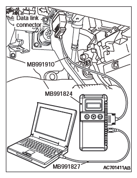
HOW TO CONNECT THE SCAN TOOL (M.U.T.-III)
Required Special Tools:
- MB991958: Scan Tool (M.U.T.-III Sub Assembly)
- MB991824: Vehicles Communication Interface (V.C.I.)
- MB991827: M.U.T.-III USB Cable
- MB991910: M.U.T.-III Main Harness A (Vehicles with CAN communication system)
CAUTION To prevent damage to scan tool MB991958, always turn the ignition switch to the "LOCK" (OFF) position before connecting or disconnecting scan tool MB991958.

1. Ensure that the ignition switch is at the "LOCK" (OFF) position.
2. Start up the personal computer.
3. Connect special tool MB991827 to special tool MB991824 and the personal computer.
4. Connect special tool MB991910 to special tool MB991824
5. Connect special tool MB991910 to the data link connector.
6. Turn the power switch of special tool MB991824 to the "ON" position.
NOTE: When the special tool MB991824 is energized, the special tool MB991824 indicator light will be illuminated in a green color.
7. Start the scan tool system on the personal computer.
NOTE: Disconnecting scan tool MB991958 is the reverse of the connecting sequence, making sure that the ignition switch is at the "LOCK" (OFF) position.
HOW TO READ AND ERASE DIAGNOSTIC TROUBLE CODES
Required Special Tools:
- MB991958: Scan Tool (M.U.T.-III Sub Assembly)
- MB991824: Vehicles Communication Interface (V.C.I.)
- MB991827: M.U.T.-III USB Cable
- MB991910: M.U.T.-III Main Harness A (Vehicles with CAN communication system)
CAUTION To prevent damage to scan tool MB991958, always turn the ignition switch to the "LOCK" (OFF) position before connecting or disconnecting scan tool MB991958.
NOTE: If the battery voltage is low, diagnostic trouble codes will not be set. Check the battery if scan tool MB991958 does not display.
1. Connect the scan tool MB991958 to the data link connector.
2. Turn the ignition switch to the "ON" position.
3. Select "System select" from the start-up screen.
4. Select "From 2006 MY" of "Model Year". When the "Vehicle Information" is displayed, check the contents.
5. Select "Air Conditioner" from "System List", and press the "OK" button.
NOTE: When the "Loading Option Setup" list is displayed, check the applicable item.
6. Select "Diagnostic Trouble Code" to read the DTC.
7. If a DTC is set, it is shown.
8. Choose "Erase DTCs" to erase the DTC.
HOW TO READ DATA LIST
Required Special Tools:
- MB991958: Scan Tool (M.U.T.-III Sub Assembly)
- MB991824: Vehicles Communication Interface (V.C.I.)
- MB991827: M.U.T.-III USB Cable
- MB991910: M.U.T.-III Main Harness A (Vehicles with CAN communication system)
CAUTION To prevent damage to scan tool MB991958, always turn the ignition switch to the "LOCK" (OFF) position before connecting or disconnecting scan tool MB991958.
1. Connect the scan tool MB991958 to the data link connector.
2. Turn the ignition switch to the "ON" position.
3. Select "System select" from the start-up screen.
4. Select "From 2006 MY" of "Model Year". When the "Vehicle Information" is displayed, check the contents.
5. Select "Air Conditioner" from "System List", and press the "OK" button.
NOTE: When the "Loading Option Setup" list is displayed, check the applicable item.
6. Select "Data List".
7. Choose an appropriate item and select the "OK" button.
HOW TO PERFORM ACTUATOR TEST
Required Special Tools:
- MB991958: Scan Tool (M.U.T.-III Sub Assembly)
- MB991824: Vehicles Communication Interface (V.C.I.)
- MB991827: M.U.T.-III USB Cable
- MB991910: M.U.T.-III Main Harness A (Vehicles with CAN communication system)
CAUTION To prevent damage to scan tool MB991958, always turn the ignition switch to the "LOCK" (OFF) position before connecting or disconnecting scan tool MB991958.
1. Connect the scan tool MB991958 to the data link connector.
2. Turn the ignition switch to the "ON" position.
3. Select "System select" from the start-up screen.
4. Select "From 2006 MY" of "Model Year". When the "Vehicle Information" is displayed, check the contents.
5. Select "Air Conditioner" from "System List", and press the "OK" button.
NOTE: When the "Loading Option Setup" list is displayed, check the applicable item.
6. Select "Actuator Test".
7. Choose an appropriate item and select the "OK" button.
HOW TO DIAGNOSE THE CAN BUS LINE
Required Special Tools:
- MB991958: Scan Tool (M.U.T.-III Sub Assembly)
- MB991824: Vehicles Communication Interface (V.C.I.)
- MB991827: M.U.T.-III USB Cable
- MB991910: M.U.T.-III Main Harness A (Vehicles with CAN communication system)
CAUTION To prevent damage to scan tool MB991958, always turn the ignition switch to the "LOCK" (OFF) position before connecting or disconnecting scan tool MB991958.
1. Connect scan tool MB991958 to the data link connector.
2. Turn the ignition switch to the "ON" position.
3. Select "CAN bus diagnosis" from the start-up screen.
4. When the vehicle information is displayed, confirm that it matches the vehicle whose CAN bus lines will be diagnosed.
- If they match, go to Step 8.
- If not, go to Step 5.
5. Select "view vehicle information" button.
6. When the vehicle information is displayed, confirm again that it matches the vehicle which is being diagnosed.
- If they match, go to Step 8.
- If not, go to Step 5.
7. Press the "OK" button.
8. When the options are displayed, choose the options (mark the check) and then select "OK".
CHECK OF FREEZE FRAME DATA
The freeze frame data can be checked by using the scan tool.
When detecting fault and storing the DTC, the ECU connected to CAN bus line obtains the data before the determination of the DTC and the data when the DTC is determined, and then stores the ECU status of that time. By analyzing the data from scan tool, the troubleshooting can be performed more efficiently.
The displayed items are as shown in the table below.
DISPLAY ITEM LIST

NOTE: *: If a failure occurs to both the ABS-ECU and ETACS-ECU, 0000 mile or FFFF km is displayed to the scan tool MB991958.
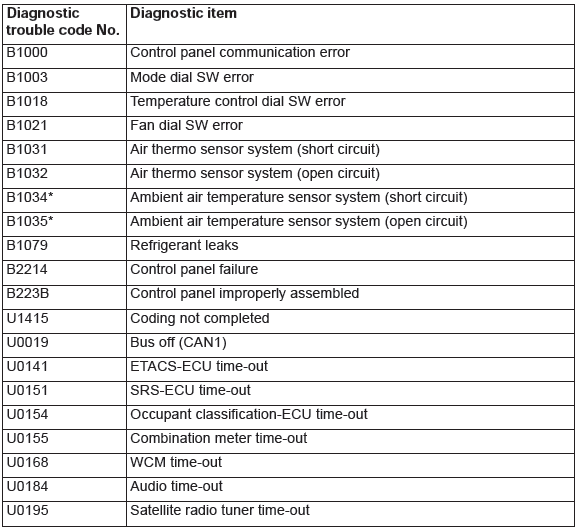
DIAGNOSTIC TROUBLE CODE CHART
CAUTION During diagnosis, a DTC code associated with other system may be set when the ignition switch is turned on with connector(s) disconnected. On completion of repairs, check all systems for DTC code(s). If DTC code(s) are set, erase them all.

- DTC B1000, B1003, B1018, B1021, B1031, B1032, B1034, B1035, B1079, B2214, B223B
- DTC U1415, U0019, U0141, U0151, U0154, U0155, U0168, U0184, U0195
- Symptom Procedures

