Mitsubishi Outlander: Symptom Procedures
INSPECTION PROCEDURE 1: When the A/C is Operation, Temperature Inside the Passenger Compartment does not Decrease (Cool Air is not Emitted).
TECHNICAL DESCRIPTION (COMMENT)
The blower system or the compressor system may be defective if there is no cool air coming from the vents.
TROUBLESHOOTING HINTS
- Malfunction of blower motor
- Malfunction of A/C-ECU
- Malfunction of A/C compressor
DIAGNOSIS
STEP 1. Using scan tool MB991958, read the diagnostic trouble code.
CAUTION To prevent damage to scan tool MB991958, always turn the ignition switch to the "LOCK" (OFF) position before connecting or disconnecting scan tool MB991958.
Check if an A/C-ECU DTC is set.
(1) Connect scan tool MB991958. Refer to "How to connect the Scan Tool (M.U.T.-III)".
(2) Turn the ignition switch to the "ON" position.
(3) Check if the DTC is set.
(4) Turn the ignition switch to the "LOCK" (OFF) position.
Q: Is the check result satisfactory?
YES : Refer to Diagnostic Trouble Code Chart.
NO : Go to Step 2.
STEP 2. Check that the blower motor operation when the blower knob is moved to the "Maximum air volume" position.
(1) Turn the ignition switch to the "ON" position.
(2) Turn the blower knob to the "Maximum air volume" position Q: Does the blower motor operate when the blower knob is moved to the "Maximum air volume" position?
YES : Go to Step 3.
NO : Refer to Inspection procedure 4 "Blower fan and motor do not turn".
STEP 3. Check the rear window defogger and outside/inside air selection damper control motor operation.
(1) Turn the ignition switch to the "ON" position.
(2) Check the operations of rear window defogger and outside/inside air selection damper control motor.
Q: Do the defogger and outside/inside air selection damper control motor work normally?
YES : Refer to Inspection procedure 3 "The A/C compressor does not Work".
NO : Refer to Inspection procedure 2, "Malfunction of the A/C-ECU power supply system".
INSPECTION PROCEDURE 2: Malfunction of the A/C-ECU Power Supply System.
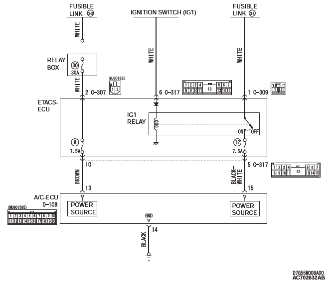
A/C-ECU Power Supply Circuit
TECHNICAL DESCRIPTION (COMMENT)
The A/C-ECU power system may be defective if the air conditioning, defogger, and outside/inside air selection damper motor all do not operate normally.
TROUBLESHOOTING HINTS
- Malfunction of the A/C-ECU
- Damaged harness wires or connectors
DIAGNOSIS
Required Special Tool:
- MB991223: Test Harness Set
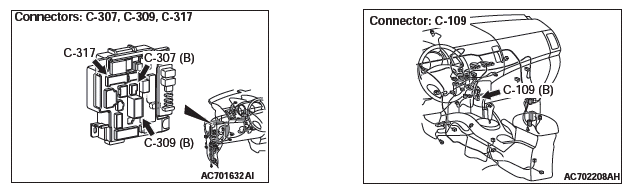
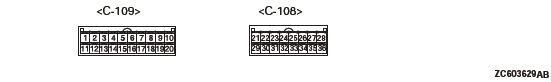
STEP 1. Check A/C-ECU connector C-109 for loose, corroded or damaged terminals, or terminals pushed back in the connector.
Q: Is A/C-ECU connector C-109 in good condition?
YES : Go to Step 2.
NO : Repair or replace the connector. Refer to GROUP 00E, Harness Connector Inspection. Check that the A/C works normally.
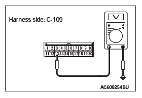
STEP 2. Measure the voltage at A/C-ECU connector C-109.
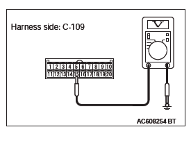
(1) Disconnect A/C-ECU connector C-109 and measure the voltage at the harness side.
(2) Turn the ignition switch to the "ON" position.
(3) Measure the voltage between terminal 15 and ground.
- The measured value should be approximately 12 volts (battery positive voltage).
Q: Is the measured voltage approximately 12 volts?
YES : Go to Step 5.
NO : Go to Step 3.
STEP 3. Check ETACS-ECU connector C-317 for loose, corroded or damaged terminals, or terminals pushed back in the connector.
Q: Is ETACS-ECU connector C-317 in good condition?
YES : Go to Step 4.
NO : Repair or replace the connector. Check that the A/C works normally.
STEP 4. Check the wiring harness between A/C-ECU connector C-109 (terminal 15) and ETACS-ECU connector C-317 (terminal 5).
- Check the A/C-ECU power supply line for open circuit.
Q: Is the wiring harness between A/C-ECU connector C-109 (terminal 15) and ETACS-ECU connector C-317 (terminal 5) in good condition?
YES : It can be assumed that this malfunction is intermittent.
Refer to GROUP 00, How to Use Troubleshooting/Inspection Service Points − How to Cope with Intermittent Malfunctions.
NO : Repair the wiring harness. Check that the A/C works normally.
STEP 5. Measure the voltage at A/C-ECU connector C-109.
(1) Disconnect A/C-ECU connector C-109 and measure the voltage at the harness side.
(2) Measure the voltage between terminal 13 and ground.
- The measured value should be approximately 12 volts (battery positive voltage).
Q: Is the measured voltage approximately 12 V?
YES : Go to Step 7.
NO : Go to Step 6.
STEP 6. Check the wiring harness between A/C-ECU connector C-109 (terminal 13) and the fusible link (36).
NOTE: Also check ETACS-ECU connectors C-307 and C-317 for loose, corroded, or damaged terminals, or terminals pushed back in the connector. If ETACS-ECU connector C-317 is damaged, repair or replace the connector as described in GROUP 00E, Harness Connector Inspection.
- Check the A/C-ECU power supply line for open circuit.
Q: Is the wiring harness between A/C-ECU connector C-109 (terminal 13) and the fusible link (36) in good condition?
YES : It can be assumed that this malfunction is intermittent.
Refer to GROUP 00, How to Use Troubleshooting/Inspection Service Points − How to Cope with Intermittent Malfunctions.
NO : Repair the wiring harness. Check that the A/C works normally.
STEP 7. Measure the resistance at A/C-ECU connector C-109.
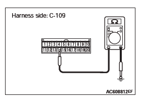
(1) Disconnect A/C-ECU connector C-109, and measure at the wiring harness side.
(2) Measure the resistance between terminal 14 and ground.
- The measured value should be 2 ohms or less.
Q: Does the measured resistance value correspond with this range?
YES : Replace the A/C-ECU, and check that the A/C works normally.
NO : Go to Step 8.
STEP 8. Check the wiring harness between A/C-ECU connector C-109 (terminal 14) and the ground.
- Check the A/C-ECU ground line for open circuit.
Q: Is the wiring harness between A/C-ECU connector C-109 (terminal 14) and ground in good condition?
YES : It can be assumed that this malfunction is intermittent.
Refer to GROUP 00, How to Use Troubleshooting/Inspection Service Points − How to Cope with Intermittent Malfunctions.
NO : Repair the wiring harness. Check that the A/C works normally.
INSPECTION PROCEDURE 3: The Compressor does not Work.
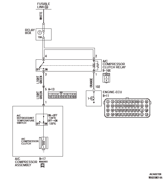
A/C Compressor Assembly Circuit
FUNCTION
Compressor that recovers the refrigerant, which evaporated in the evaporator and became a high-temperature and high-pressure gas, and turns it into liquid again.
PROBABLE CAUSES
- Insufficient refrigerant
- Malfunction of connector.
- Malfunction of the harness (A/C compressor circuit is open/shorted to ground)
- Malfunction of the A/C pressure sensor.
- Malfunction of the A/C compressor.
- Malfunction of the A/C compressor clutch relay.
- Malfunction of the A/C-ECU.
DIAGNOSIS
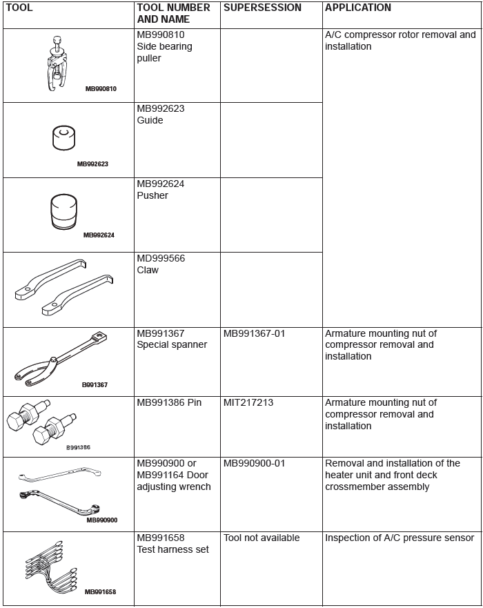
Required Special Tools:
- MB991223: Harness Set
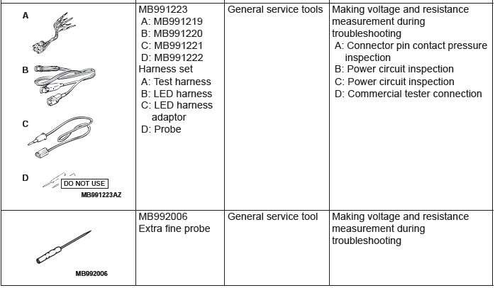
- MB992006: Extra Fine Probe
- MB991658: Test Harness Set
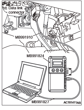
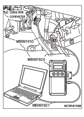
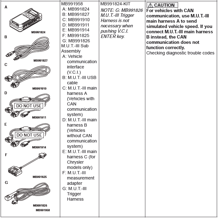
- MB991958: Scan Tool (M.U.T.-III Sub Assembly)
- MB991824: V.C.I.
- MB991827: M.U.T.-III USB Cable
- MB991910: M.U.T.-III Main Harness A
STEP 1. Using scan tool MB991958, diagnose the CAN bus line.
CAUTION To prevent damage to scan tool MB991958, always turn the ignition switch to the "LOCK" (OFF) position before connecting or disconnecting scan tool MB991958.
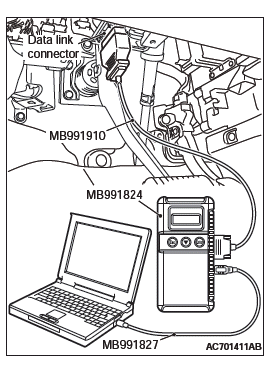
(1) Connect scan tool MB991958. Refer to "How to connect the Scan Tool (M.U.T.-III)".
(2) Turn the ignition switch to the "ON" position.
(3) Diagnose the CAN bus line.
(4) Turn the ignition switch to the "LOCK" (OFF) position.
Q: Is the CAN bus line found to be normal?
YES : Go to Step 2.
NO : Repair the CAN bus lines.
STEP 2. Using scan tool MB991958, read the diagnostic trouble code.
Check if an A/C-ECU DTC is set.
(1) Connect scan tool MB991958 to the data link connector.
(2) Turn the ignition switch to the "ON" position.
(3) Check if the DTC is set.
(4) Turn the ignition switch to the "LOCK" (OFF) position.
Q: Is the check result satisfactory?
YES : Refer to Diagnostic Trouble Code Chart.
NO : Go to Step 3.
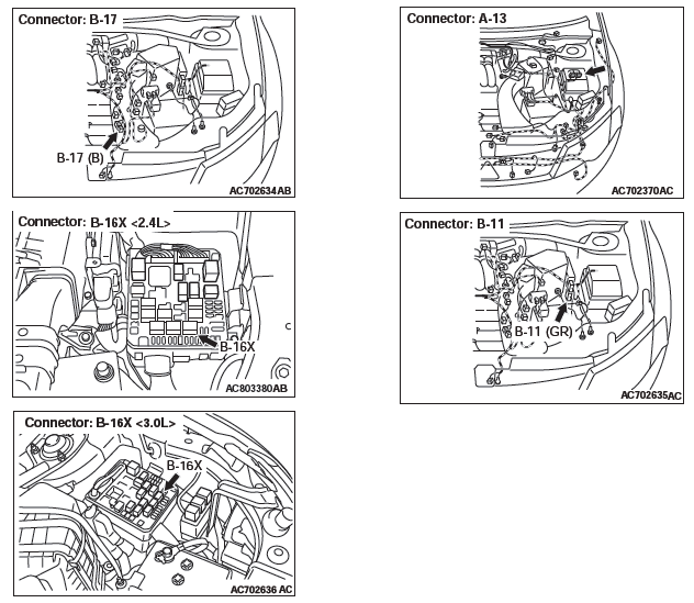
STEP 3. Check A/C compressor assembly connector B-17 for loose, corroded or damaged terminals, or terminals pushed back in the connector.
Q: Is A/C compressor assembly connector B-17 in good condition?
YES : Go to Step 4.
NO : Repair or replace the connector.
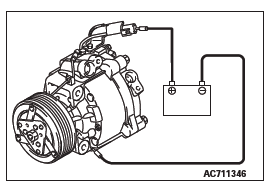
STEP 4. Check the A/C compressor clutch operation.
Connect the compressor connector terminal to the battery positive (+) terminal and ground the battery's negative (-) terminal to the compressor unit. At that time, the A/C compressor clutch should make a definite operating sound.
Q: Can the sound (click) of the A/C compressor clutch operation be heard?
YES : Go to Step 5.
NO : Replace the compressor magnet clutch.
STEP 5. Check A/C compressor clutch relay connector B-16X for loose, corroded or damaged terminals, or terminals pushed back in the connector.
Q: Is A/C compressor clutch relay connector B-16X in good condition?
YES : Go to Step 6.
NO : Repair or replace the connector.
STEP 6. Check the A/C compressor clutch relay continuity.
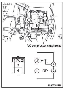
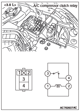
Follow the table below to check the A/C compressor clutch relay for continuity.
Q: Is the A/C compressor clutch relay in good condition?
YES : Go to Step 7.
NO : Replace the A/C compressor clutch relay.
STEP 7. Check engine control module connector B-11 for loose, corroded or damaged terminals, or terminals pushed back in the connector.
Q: Is engine control module connector B-11 in good condition?
YES : Go to Step 8.
NO : Repair or replace the connector.
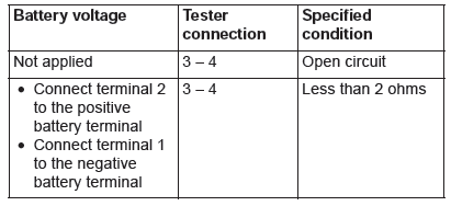
STEP 8. Measure the voltage at A/C compressor assembly connector B-17.
(1) Disconnect A/C compressor assembly connector B-17 and measure the voltage at the wiring harness side.
(2) Disconnect powertrain control module connector B-11 and ground harness side terminal No.102.
(3) Turn the ignition switch to the "ON" position.
(4) A/C compressor assembly connector B-17 terminal 1 and ground.
- The measured value should be approximately 12 volts (battery positive voltage).
Q: Is the measured voltage approximately 12 volts?
YES : Go to Step 13.
NO : Go to Step 9.
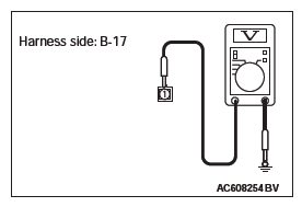
STEP 9. Measure the voltage at A/C compressor clutch relay connector B-16X.
(1) Disconnect A/C compressor connector B-16X and measure the voltage at the relay box side.
(2) Turn the ignition switch to the "ON" position.
(3) Measure the voltage between terminal 4 and ground.
- The measured value should be approximately 12 volts (battery positive voltage).
(4) Measure the voltage between terminal 2 and ground.
- The measured value should be approximately 12 volts (battery positive voltage).
Q: Is the measured voltage approximately 12 volts?
YES : Go to Step 11.
NO : Go to Step 10.
STEP 10. Check the wiring harness between A/C compressor clutch relay connector B-16X (terminals 2 and 4) and the fusible link (36).
- Check the A/C compressor clutch relay power supply line for open circuit.
Q: Is the wiring harness between A/C compressor clutch relay connector B-16X (terminals 2 and 4) and the fusible link (36) in good condition?
YES : It can be assumed that this malfunction is intermittent.
Refer to GROUP 00, How to Use Troubleshooting/Inspection Service Points − How to Cope with Intermittent Malfunctions.
NO : Repair the wiring harness. Check that the A/C works normally.
STEP 11. Check the wiring harness between A/C compressor clutch relay connector B-16X (terminal 3) and A/C compressor assembly connector B-17 (terminal 1).
NOTE: Also check intermediate connector A-13 for loose, corroded, or damaged terminals, or terminals pushed back in the connector. If intermediate connector A-13 is damaged, repair or replace the connector as described in GROUP 00E, Harness Connector Inspection.
- Check the A/C compressor assembly power supply line for open circuit.
Q: Is the wiring harness between A/C compressor clutch relay connector B-16X (terminal 3) and A/C compressor assembly connector B-17 (terminal 1) in good condition?
YES : Go to Step 12.
NO : Repair the wiring harness. Check that the A/C works normally.
STEP 12. Check the wiring harness between powertrain control module connector B-11 (terminal 102) and A/C compressor clutch relay connector B-16X (terminal 1).
- Check the powertrain control module signal line for open and short circuit.
Q: Is the wiring harness between powertrain control module connector B-11 (terminal 102) and A/C compressor clutch relay connector B-16X (terminal 1) in good condition?
YES : It can be assumed that this malfunction is intermittent.
Refer to GROUP 00, How to Use Troubleshooting/Inspection Service Points − How to Cope with Intermittent Malfunctions.
NO : Repair the wiring harness. Check that the A/C works normally.
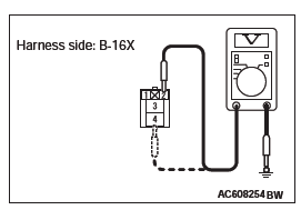
STEP 13. Check the refrigerant temperature switch.
CAUTION Do not heat more than necessary.
(1) Dip the metal part of the cooling temperature switch into engine oil and increase the oil temperature using a gas burner or similar.
(2) When the oil temperature reaches the standard value, check that voltage is supplied between the terminals.
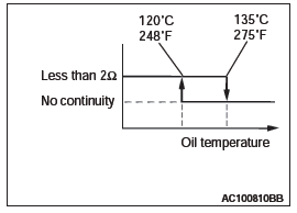
Standard value:
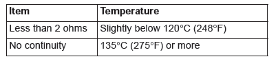
NOTE: When the oil temperature is 135ºC (275ºF) or more and there is no continuity, the resistance will not be 2Ω or lower until the oil temperature reduces to 120ºC (248ºF) or less.
Q: Is the refrigerant temperature switch operating properly?
YES : Go to Step 14.
NO : Replace the refrigerant temperature switch. Check that the A/C works normally.
STEP 14. Replace the A/C-ECU.
Q: Does the A/C operate normally?
YES : No action is necessary and testing is complete.
NO : Replace the powertrain control module. Check that the A/C works normally.
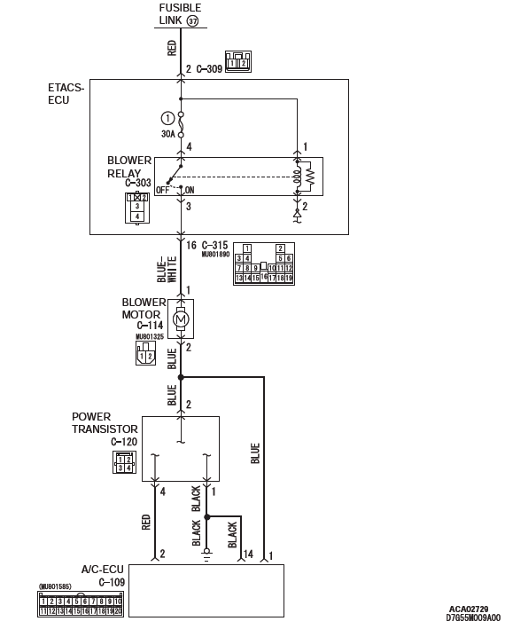
INSPECTION PROCEDURE 4: Blower Fan and Motor do not Turn.
Blower Motor Circuit
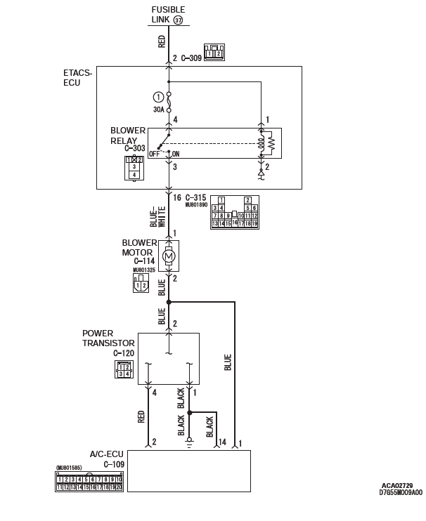
CIRCUIT OPERATION
If the blower motor does not operate, the blower relay system is suspected.
TROUBLESHOOTING HINTS
- Malfunction of the power transistor
- Malfunction of the blower motor
- Malfunction of the A/C-ECU
- Damaged harness wires or connectors
DIAGNOSIS
Required Special Tools:
- MB991223: Harness Set
- MB992006: Extra Fine Probe
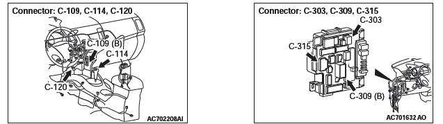
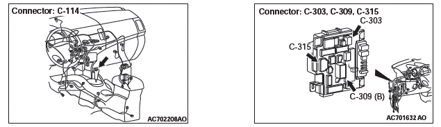
STEP 1. Check blower motor connector C-114 for loose, corroded or damaged terminals, or terminals pushed back in the connector.
Q: Is blower motor connector C-114 in good condition?
YES : Go to Step 2.
NO : Repair or replace the connector. The blower motor should operate normally.
STEP 2. Measure the voltage at blower motor connector C-114.
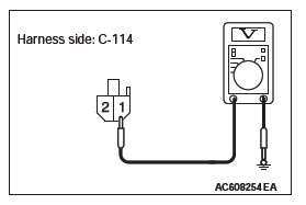
(1) Disconnect blower motor connector C-114, and measure the voltage at the wiring harness side.
(2) Turn the ignition switch to the "ON" position.
(3) Turn the blower switch to the "Maximum air volume" position.
(4) Measure the voltage between terminal 1 and ground.
- The measured value should be approximately 12 volts (battery positive voltage).
Q: Is the measured voltage approximately 12 volts?
YES : Go to Step 3.
NO : Refer to Inspection procedure 10, "Blower motor power supply system".
STEP 3. Check blower motor connector C-114 for loose, corroded or damaged terminals, or terminals pushed back in the connector.
Q: Is blower motor connector C-114 in good condition?
YES : Go to Step 4.
NO : Repair or replace the connector. The blower motor should operate normally.
STEP 4. Check the blower fan and motor operation.
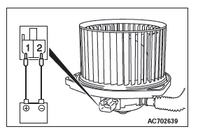
When battery voltage is applied between the terminals, check that the motor operates. Also, check that there is no abnormal noise.
Q: Is there any abnormal noise?
YES : Go to Step 5.
NO : Replace the blower relay. The blower motor should operate normally.
STEP 5. Check A/C-ECU connector C-109 for loose, corroded or damaged terminals, or terminals pushed back in the connector.
Q: Is A/C-ECU connector C-109 in good condition?
YES : Go to Step 6.
NO : Repair or replace the connector. The blower motor should operate normally.
STEP 6. Check the wiring harness between A/C-ECU connector C-109 (terminal 1) and blower motor connector C-114 (terminal 2).
- Check the AC-ECU signal line for open and short circuit.
Q: Is the wiring harness between A/C-ECU connector C-109 (terminal 1) and blower motor connector C-114 (terminal 2) in good condition?
YES : Go to Step 7.
NO : Repair the wiring harness. The blower motor should operate normally.
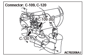
STEP 7. Check power transistor connector C-120 for loose, corroded or damaged terminals, or terminals pushed back in the connector.
Q: Is power transistor connector C-120 in good condition?
YES : Go to Step 8.
NO : Repair or replace the connector. The blower motor should operate normally.
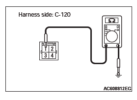
STEP 8. Measure the resistance at power transistor connector C-120.
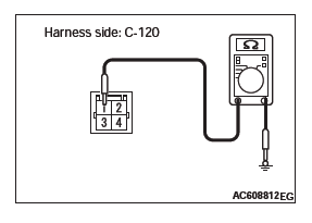
(1) Disconnect power transistor connector C-120, and measure the resistance at the wiring harness side.
(2) Measure the resistance value between terminal 1 and ground.
OK: The measured value should be 2 ohms or less.
Q: Does the measured resistance value correspond with this range?
YES : Go to Step 10.
NO : Go to Step 9.
STEP 9. Check the wiring harness between power transistor connector C-120 (terminal 1) and ground.
- Check the power transistor ground line for open circuit.
Q: Is the wiring harness between power transistor connector C-120 (terminal 1) and ground in good condition?
YES : It can be assumed that this malfunction is intermittent.
Refer to GROUP 00, How to Use Troubleshooting/Inspection Service Points − How to Cope with Intermittent Malfunctions.
NO : Repair the wiring harness. The blower motor should operate normally.
STEP 10. Check the wiring harness between A/C-ECU connector C-109 (terminals 1,2 and 14) and power transistor connector C-120 (terminals 2 and 4).
- Check the AC-ECU signal line for open and short circuit.
Q: Is the wiring harness between A/C-ECU connector C-109 (terminals 1 and 2) and power transistor connector C-120 (terminals 2 and 4) in good condition?
YES : Go to Step 11.
NO : Repair the wiring harness. The blower motor should operate normally.
STEP 11. Replace the power transistor and check the trouble symptom again.
Check the trouble symptom again.
Q: Is the check result satisfactory?
YES : The procedure is complete.
NO : Replace the A/C-ECU.
INSPECTION PROCEDURE 5: Blower Air Amount cannot be Changed.
Blower Motor Circuit
CIRCUIT OPERATION
If the blower motor speed cannot be changed, the power transistor circuit is suspected.
TROUBLESHOOTING HINTS
- Malfunction of the power transistor
- Malfunction of the A/C-ECU
- Damaged harness wires or connectors
DIAGNOSIS
Required Special Tools:
- MB991223: Harness Set
- MB992006: Extra Fine Probe
STEP 1. Check power transistor connector C-120 for loose, corroded or damaged terminals, or terminals pushed back in the connector.
Q: Is power transistor connector C-120 in good condition?
YES : Go to Step 2.
NO : Repair or replace the connector.The blower motor should operate normally.
STEP 2. Measure the resistance at power transistor connector C-120.
(1) Disconnect power transistor connector C-120, and measure the resistance at the wiring harness side.
(2) Measure the resistance value between terminal 1 and ground.
OK: The measured value should be 2 ohms or less.
Q: Does the measured resistance value correspond with this range?
YES : Go to Step 4.
NO : Go to Step 3.
STEP 3. Check the wiring harness between power transistor connector C-120 (terminal 1) and ground.
- Check the power transistor ground line for open circuit.
Q: Is the wiring harness between power transistor connector C-120 (terminal 1) and ground in good condition?
YES : It can be assumed that this malfunction is intermittent.
Refer to GROUP 00, How to Use Troubleshooting/Inspection Service Points − How to Cope with Intermittent Malfunctions.
NO : Repair the wiring harness. The blower motor should operate normally.
STEP 4. Check A/C-ECU connector C-109 for loose, corroded or damaged terminals, or terminals pushed back in the connector.
Q: Is A/C-ECU connector C-109 in good condition?
YES : Go to Step 5.
NO : Repair or replace the connector. The blower motor should operate normally.
STEP 5. Check the wiring harness between A/C-ECU connector C-109 (terminals 1,2 and 14) and power transistor connector C-120 (terminals 2 and 4).
- Check the AC-ECU signal line for open and short circuit.
Q: Is the wiring harness between A/C-ECU connector C-109 (terminals 1 and 2) and power transistor connector C-120 (terminals 2 and 4) in good condition?
YES : Go to Step 6.
NO : Repair the wiring harness. The blower motor should operate normally.
STEP 6. Replace the power transistor and check the trouble symptom again.
Check the trouble symptom again.
Q: Is the check result satisfactory?
YES : The procedure is complete.
NO : Replace the A/C-ECU.
INSPECTION PROCEDURE 6: Outside/Inside Air Changeover is not possible.
Outside/Inside Air Selection Damper Control Motor Circuit
CIRCUIT OPERATION
If the outside/inside air selection damper control motor does not operate normally, the outside/inside air selection damper control motor system may be defective.
TROUBLESHOOTING HINTS
- Malfunction of the outside/inside air selection damper control motor
- Malfunction of the A/C-ECU
- Damaged harness wires or connectors
DIAGNOSIS
Required Special Tools:
- MB991223: Harness Set
- MB992006: Extra Fine Probe
- MB991958: Scan Tool (M.U.T.-III Sub Assembly)
- MB991824: V.C.I.
- MB991827: M.U.T.-III USB Cable
- MB991910: M.U.T.-III Main Harness A
STEP 1. Using scan tool MB991958, read the diagnostic trouble code.
CAUTION To prevent damage to scan tool MB991958, always turn the ignition switch to the "LOCK" (OFF) position before connecting or disconnecting scan tool MB991958.
Check if an A/C-ECU DTC is set.
(1) Connect scan tool MB991958. Refer to "How to connect the Scan Tool (M.U.T.-III)".
(2) Turn the ignition switch to the "ON" position.
(3) Check if the DTC is set.
(4) Turn the ignition switch to the "LOCK" (OFF) position.
Q: Is the check result satisfactory?
YES : Go to Step 2.
NO : Refer to DIAGNOSTIC TROUBLE CODE CHART.
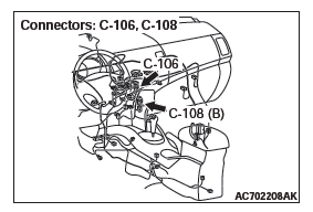
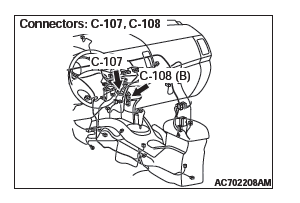
STEP 2. Check outside/inside air selection damper control motor connector C-106 and A/C-ECU connector C-108 for loose, corroded or damaged terminals, or terminals pushed back in the connector.
Q: Are outside/inside air selection damper control motor connector C-106 and A/C-ECU connector C-108 in good condition?
YES : Go to Step 3.
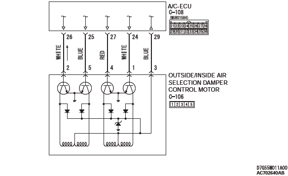
NO : Repair or replace the connector. Check that the A/C works normally.
STEP 3. Check the wiring harness between A/C-ECU connector C-108 (terminals 26, 25, 27, 24 and 29) and outside/inside air selection damper control motor connector C-106 (terminals 2, 5, 4. 1 and 3).
- Check the AC-ECU signal line for open and short circuit.
Q: Are the wiring harness between A/C-ECU connector C-108 (terminals 26, 25, 27, 24 and 29) and outside/inside air selection damper control motor connector C-106 (terminals 2, 5, 4. 1 and 3) in good condition?
YES : Go to Step 4.
NO : Repair the wiring harness. Check that the A/C works normally.
STEP 4. Replace the power transistor and check the trouble symptom again.
Check the trouble symptom again.
Q: Is the check result satisfactory?
YES : The procedure is complete.
NO : Replace the A/C-ECU.
INSPECTION PROCEDURE 7: A/C Outlet Air Temperature does not Increase
Air Mixing Damper Control Motor Circuit
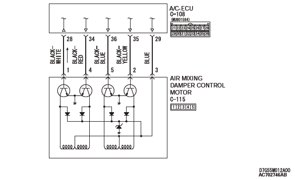
CIRCUIT OPERATION
If the air outlet temperature cannot be adjusted, the air mixing damper control motor circuit may be failed.
TROUBLESHOOTING HINTS
- Malfunction of the air mixing damper control motor
- Malfunction of the A/C-ECU
- Damaged harness wires or connectors
DIAGNOSIS
Required Special Tools:
- MB991223: Harness Set
- MB992006: Extra Fine Probe
- MB991958: Scan Tool (M.U.T.-III Sub Assembly)
- MB991824: V.C.I.
- MB991827: M.U.T.-III USB Cable
- MB991910: M.U.T.-III Main Harness A
STEP 1. Using scan tool MB991958, read the diagnostic trouble code.
Check if an A/C-ECU DTC is set.
(1) Connect scan tool MB991958 to the data link connector.
(2) Turn the ignition switch to the "ON" position.
(3) Check if the DTC is set.
(4) Turn the ignition switch to the "LOCK" (OFF) position.
Q: Is the check result satisfactory?
YES : Go to Step 2.
NO : Refer to DIAGNOSTIC TROUBLE CODE CHART.
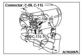
STEP 2. Check air mixing damper control motor connector C-115 and A/C-ECU connector C-108 for loose, corroded or damaged terminals, or terminals pushed back in the connector.
Q: Are air mixing damper control motor connector C-115 and A/C-ECU connector C-108 in good condition?
YES : Go to Step 3.
NO : Repair or replace the connector. Check that the A/C works normally.
STEP 3. Check the wiring harness between A/C-ECU connector C-108 (terminals 29, 35, 36, 34 and 28) and air mixing damper control motor connector C-115 (terminals 3, 2, 5. 4 and 1).
- Check the A/C-ECU signal line for open and short circuit.
Q: Are the wiring harness between A/C-ECU connector C-108 (terminals 29, 35, 36, 34 and 28) and air mixing damper control motor connector C-115 (terminals 3, 2, 5. 4 and 1) in good condition?
YES : Go to Step 4.
NO : Repair the wiring harness. Check that the A/C works normally.
STEP 4. Replace the power transistor and check the trouble symptom again. Check the trouble symptom again.
Q: Is the check result satisfactory?
YES : The procedure is complete.
NO : Replace the A/C-ECU.
INSPECTION PROCEDURE 8: Air Outlet Vent cannot be Changed.
Mode Selection Damper Control Motor Circuit
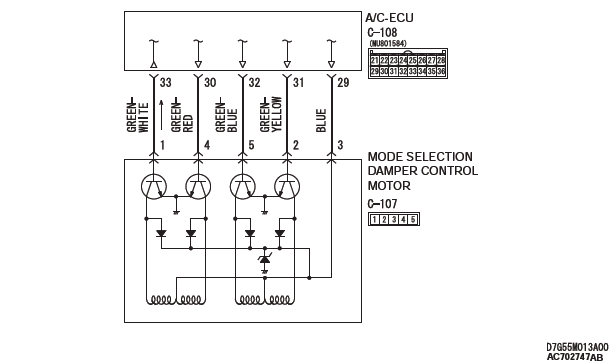
CIRCUIT OPERATION
If the air outlet cannot be switched, the mode selection damper control motor circuit may be failed.
TROUBLESHOOTING HINTS
- Malfunction of the mode selection damper control motor
- Malfunction of the A/C-ECU
- Damaged harness wires or connectors
DIAGNOSIS
Required Special Tools:
- MB991223: Harness Set
- MB992006: Extra Fine Probe
- MB991958: Scan Tool (M.U.T.-III Sub Assembly)
- MB991824: V.C.I.
- MB991827: M.U.T.-III USB Cable
- MB991910: M.U.T.-III Main Harness A
STEP 1. Using scan tool MB991958, read the diagnostic trouble code.
Check if an A/C-ECU DTC is set.
(1) Connect scan tool MB991958 to the data link connector.
(2) Turn the ignition switch to the "ON" position.
(3) Check if the DTC is set.
(4) Turn the ignition switch to the "LOCK" (OFF) position.
Q: Is the check result satisfactory?
YES : Go to Step 2.
NO : Refer to DIAGNOSTIC TROUBLE CODE CHART.
STEP 2. Check mode selection damper control motor connector C-107 and A/C-ECU connector C-108 for loose, corroded or damaged terminals, or terminals pushed back in the connector.
Q: Are mode selection damper control motor connector C-107 and A/C-ECU connector C-108 in good condition?
YES : Go to Step 3.
NO : Repair or replace the connector. Check that the A/C works normally.
STEP 3. Check the wiring harness between A/C-ECU connector C-108 (terminals 29, 31, 32, 30 and 33) and mode selection damper control motor connector C-107 (terminals 3, 2, 5. 4 and 1).
- Check the A/C-ECU signal line for open and short circuit.
Q: Are the wiring harness between A/C-ECU connector C-108 (terminals 29, 31, 32, 30 and 33) and mode selection damper control motor connector C-107 (terminals 3, 2, 5. 4 and 1) in good condition?
YES : Go to Step 4.
NO : Repair the wiring harness. Check that the A/C works normally.
STEP 4. Replace the power transistor and check the trouble symptom again.
Check the trouble symptom again.
Q: Is the check result satisfactory?
YES : The procedure is complete.
NO : Replace the A/C-ECU.
INSPECTION PROCEDURE 9: Rear window defogger does not operate.
Rear Window Defogger Circuit
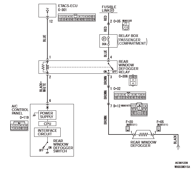
TECHNICAL DESCRIPTION (COMMENT)
If the defogger does not operate when the rear window defogger switch is turned on, the rear window defogger relay system may be defective.
TROUBLESHOOTING HINTS
- Malfunction of the A/C-ECU
- Malfunction of the rear window defogger relay
- Damaged harness wires or connectors
DIAGNOSIS
Required Special Tools:
- MB991223: Harness Set
- MB992006: Extra Fine Probe
STEP 1. Check the A/C and outside/inside air selection damper control motor operation.
Q: Do the A/C and outside/inside air selection damper control motor work normally?
YES : Go to Step 2.
NO : Refer to Inspection procedure 2, "Malfunction of the A/C-ECU power supply system".
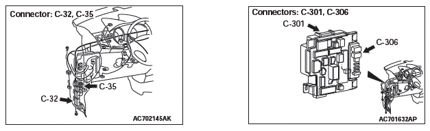
STEP 2. Check rear window defogger relay connector C-306 for loose, corroded or damaged terminals, or terminals pushed back in the connector.
Q: Is rear window defogger relay connector C-306 in good condition?
YES : Go to Step 3.
NO : Repair or replace the connector. The rear window defogger system should work normally.
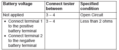
STEP 3. Check the rear window defogger relay continuity.
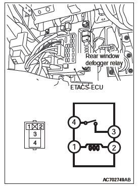
Follow the table below to check the rear window defogger relay for continuity.
Q: Is the rear window defogger relay in good condition?
YES : Go to Step 4.
NO : Replace the rear window defogger relay. The rear window defogger system should work normally.
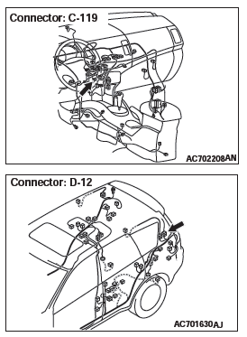
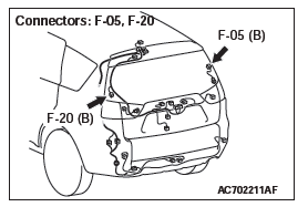
STEP 4. Check rear window defogger connector F-20 and A/C control panel connector C-119 for loose, corroded or damaged terminals, or terminals pushed back in the connector.
Q: Are rear window defogger connector F-20 and A/C control panel connector C-119 in good condition?
YES : Go to Step 5.
NO : Repair or replace the connector. The rear window defogger system should work normally.
STEP 5. Measure the voltage at rear window defogger connector F-20.
(1) Disconnect rear window defogger connector F-20, and measure the voltage at the harness side.
(2) Disconnect A/C-control panel connector C-119 and ground harness side terminal No.6.
(3) Turn the ignition switch to the "ON" position.
(4) Measure the voltage between rear window defogger connector F-20 terminal No.1 and ground.
- The measured value should be approximately 12 volts (battery positive voltage).
Q: Is the measured voltage approximately 12 volts?
YES : Go to Step 13.
NO : Go to Step 6.
STEP 6. Measure the voltage at rear window defogger relay connector C-306.
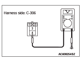
(1) Disconnect rear window defogger relay connector C-306, and measure the voltage at the junction block side.
(2) Measure the voltage between terminal 4 and ground.
- The measured value should be approximately 12 volts (battery positive voltage).
Q: Is the measured voltage approximately 12 volts?
YES : Go to Step 8.
NO : Go to Step 7.
STEP 7. Check the wiring harness between rear window defogger relay connector C-306 (terminal 4) and the fusible link (37).
NOTE: Also check intermediate connector C-35 for loose, corroded, or damaged terminals, or terminals pushed back in the connector. If intermediate connector C-35 is damaged, repair or replace the connector as described in GROUP 00E, Harness Connector Inspection.
- Check the rear window defogger relay power supply line for open circuit.
Q: Is the wiring harness between rear window defogger relay connector C-306(terminal 4) and the fusible link (37) in good condition?
YES : Check that the rear window defogger system works normally.
NO : Repair the wiring harness. Check that the rear window defogger system works normally.
STEP 8. Measure the voltage at rear window defogger relay connector C-306.
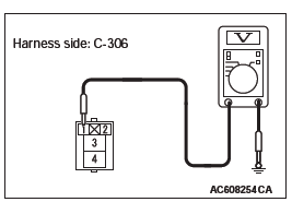
(1) Disconnect rear window defogger relay connector C-306, and measure the voltage at the junction block side.
(2) Turn the ignition switch to the "ON" position.
(3) Measure the voltage between terminal 1 and ground.
- The measured value should be approximately 12 volts (battery positive voltage).
Q: Is the measured voltage approximately 12 volts?
YES : Go to Step 11.
NO : Go to Step 9.
STEP 9. Check ETACS-ECU connector C-301 for loose, corroded or damaged terminals, or terminals pushed back in the connector.
Q: Is ETACS-ECU connector C-301 in good condition?
YES : Go to Step 10.
NO : Repair or replace the connector. Check that the rear window defogger system works normally.
STEP 10. Check the wiring harness between rear window defogger relay connector C-306 (terminal 1) and ETACS-ECU C-301 (terminal 12).
- Check the rear window defogger relay power supply line for open circuit.
Q: Is the wiring harness between rear window defogger relay connector C-306 (terminal 1) and ETACS-ECU C-301 (terminal 12) in good condition?
YES : Check that the rear window defogger system works normally.
NO : Repair the wiring harness. Check that the rear window defogger system works normally.
STEP 11. Check the wiring harness between rear window defogger relay connector C-306 (terminal 2) and A/C-control panel connector C-119 (terminal 6).
- Check the A/C-ECU signal line for open and short circuit.
Q: Is the wiring harness between rear window defogger relay connector C-306 (terminal 2) and A/C-control panel connector C-119 (terminal 6) in good condition?
YES : Go to Step 12.
NO : Repair or replace the wiring harness. Check that the rear window defogger system works normally.
STEP 12. Check the wiring harness between rear window defogger relay connector C-306 (terminal 3) and rear window defogger connector F-20 (terminal 1).
NOTE: Also check intermediate connector C-32 and D-12 for loose, corroded, or damaged terminals, or terminals pushed back in the connector. If intermediate connector C-32 and D-12 is damaged, repair or replace the connector as described in GROUP 00E, Harness Connector Inspection.
- Check the rear window defogger power supply line for open circuit.
Q: Is the wiring harness between rear window defogger relay connector C-306 (terminal 3) and rear window defogger connector F-20 (terminal 1) in good condition?
YES : It can be assumed that this malfunction is intermittent.
Refer to GROUP 00, How to Use Troubleshooting/Inspection Service Points − How to Cope with Intermittent Malfunctions.
NO : Repair or replace the wiring harness. Check that the rear window defogger system works normally.
STEP 13. Check rear window defogger connector F-05 for loose, corroded or damaged terminals, or terminals pushed back in the connector.
Q: Is rear window defogger connector F-05 in good condition?
YES : Go to Step 14.
NO : Repair or replace the connector. Check that the rear window defogger system works normally.
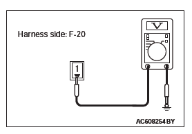
STEP 14. Measure the resistance at rear window defogger connector F-05.
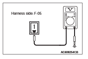
(1) Disconnect rear window defogger connector F-05, and measure at the wiring harness side.
(2) Measure the resistance between terminal 1 and ground.
- The measured value should be 2 ohms or less.
Q: Does the measured resistance value correspond with this range?
YES : Go to Step 16.
NO : Go to Step 15.
STEP 15. Check the wiring harness between rear window defogger connector F-05 (terminal 1) and the ground.
- Check the rear window defogger ground line for open circuit.
Q: Is the wiring harness between rear window defogger connector F-05 (terminal 1) and the ground in good condition?
YES : Check that the rear window defogger system works normally.
NO : Repair or replace the wiring harness. Check that the rear window defogger system works normally.
STEP 16. Check the rear window defogger.
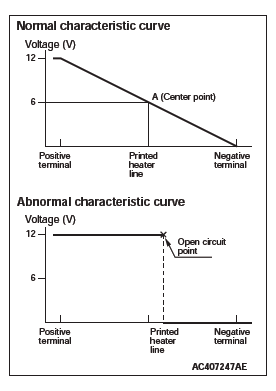
(1) Let the engine run at 2,000 r/min, and check the printed heater with the battery fully charged.
(2) Turn on the rear window defogger switch, and use a voltmeter to measure the voltage in each printed heater at middle point A on the rear window glass.
- The value should be approximately 6 volts.
Q: Does the rear window defogger work normally?
YES : Replace the A/C-ECU. Check that the rear window defogger system works normally.
NO : Repair the rear window defogger.
INSPECTION PROCEDURE 10: Blower Motor power supply system.
Blower Motor Circuit
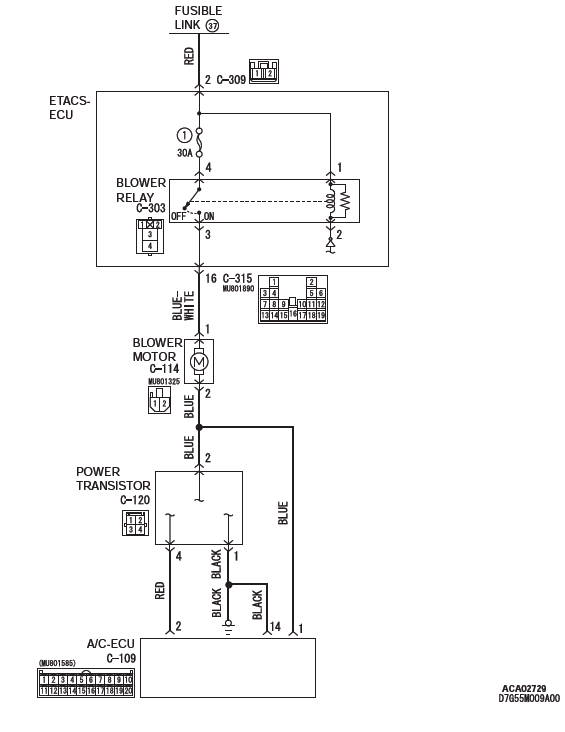
TECHNICAL DESCRIPTION (COMMENT)
If the voltage is not supplied to the blower motor, the blower relay system may be failed.
TROUBLESHOOTING HINTS
- Malfunction of the ETACS-ECU
- Malfunction of the blower relay
- Damaged harness wires or connectors
DIAGNOSIS
Required Special Tools:
- MB991223: Harness Set
- MB992006: Extra Fine Probe
STEP 1. Check blower relay connector C-303 for loose, corroded or damaged terminals, or terminals pushed back in the connector.
Q: Is blower relay connector C-303 in good condition?
YES : Go to Step 2.
NO : Repair or replace the connector.
STEP 2. Check the blower relay continuity.
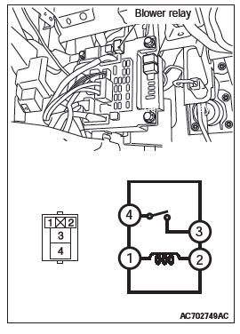
Follow the table below to check the blower relay for continuity.
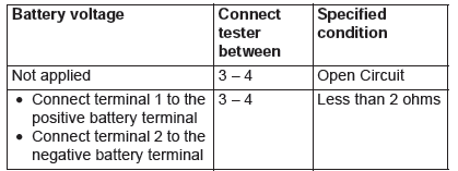
Q: Is the blower relay in good condition?
YES : Go to Step 3.
NO : Replace the rear window defogger relay.
STEP 3. Measure the voltage at blower relay connector C-303.
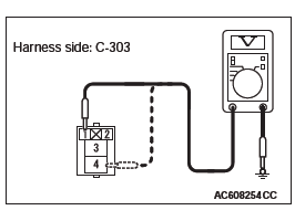
(1) Disconnect blower relay connector C-303, and measure the voltage at the junction block side.
(2) Measure the voltage between terminals 1 and ground.
- The measured value should be approximately 12 volts (battery positive voltage).
(3) Measure the voltage between terminals 4 and ground.
- The measured value should be approximately 12 volts (battery positive voltage).
Q: Is the measured voltage approximately 12 volts?
YES : Go to Step 5.
NO : Go to Step 4.
STEP 4. Check the wiring harness between blower relay connector C-303 (terminals 1 and 4) and the fusible link (37).
NOTE: Also check ETACS-ECU connector C-309 for loose, corroded, or damaged terminals, or terminals pushed back in the connector. If ETACS-ECU connector C-309 is damaged, repair or replace the connector as described in GROUP 00E, Harness Connector Inspection.
- Check the blower relay power supply line for open circuit.
Q: Is the wiring harness between blower relay connector C-303 (terminals 1 and 4) and the fusible link (37) in good condition?
YES : It can be assumed that this malfunction is intermittent.
Refer to GROUP 00, How to Use Troubleshooting/Inspection Service Points − How to Cope with Intermittent Malfunctions.
NO : Repair or replace the wiring harness.
STEP 5. Check blower relay connector C-114 for loose, corroded or damaged terminals, or terminals pushed back in the connector.
Q: Is blower relay connector C-114 in good condition?
YES : Go to Step 6.
NO : Repair or replace the connector.
STEP 6. Check the wiring harness between blower relay connector C-303 (terminal 3) and blower motor connector C-114 (terminal 1).
NOTE: Also check ETACS-ECU connector C-315 for loose, corroded, or damaged terminals, or terminals pushed back in the connector. If ETACS-ECU connector C-315 is damaged, repair or replace the connector as described in GROUP 00E, Harness Connector Inspection.
- Check the blower motor power supply line for open circuit.
Q: Is the wiring harness between blower relay connector C-303 (terminal 3) and blower motor connector C-114 (terminal 1) in good condition?
YES : It can be assumed that this malfunction is intermittent.
Refer to GROUP 00, How to Use Troubleshooting/Inspection Service Points − How to Cope with Intermittent Malfunctions.
NO : Repair or replace the wiring harness.
DATA LIST REFERENCE TABLE
Refer to GROUP 55B - Data list reference table.
ACTUATOR TEST REFERENCE
Refer to GROUP 55B - Actuator test reference.
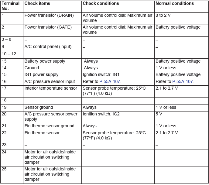
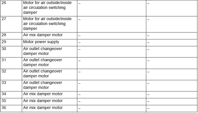
CHECK AT A/C-ECU TERMINAL
Special Tools
READ NEXT:
 On-vehicle Service
CHECK AT A/C-ECU TERMINAL
1. Disconnect the A/C compressor clutch connector to the A/C
compressor clutch.
2. Connect positive battery voltage directly to the connector for
the A/C compressor clutch.
Heater Unit, Heater Core,
Blower Assembly and
Evaporator Unit
HEATER UNIT AND FRONT DECK CROSSMEMBER ASSEMBLY REMOVAL AND
INSTALLATION
Pre-removal operation
Engine Coolant Draining
Discharging refrigerant
Front seat assembly removal
Rear heater duct remo
Compressor Assembly
REMOVAL AND INSTALLATION
Pre-removal Operation
Refrigerant Discharging
Front bumper under cover
Front under cover RH
Drive belt removal <2.4L>
Drive belt removal <3.0L>
Post-instal
SEE MORE:
Charging System
GENERAL INFORMATION
The charging system charges the battery with the
generator output to keep the battery charged at a
constant level during varying electrical load.
OPERATION
Rotation of the excited field coil generates AC voltage
in the stator.
This alternating current is rectified through diode
DTC C1041, C1042, C1043, C1044, C1046, C1047, C1048, C1049, C104B,
C104F, C1053, C1057, C105F, C1063, C1067, C105B
DTC C1041: Abnormality in periodical signal for FL wheel speed sensor
CAUTION
If there is any problem in the CAN bus lines, an incorrect
DTC may be set. Prior to this diagnosis, diagnose
the CAN bus lines (Refer to GROUP 54C − CAN Bus
Line Diagnostic Flow).
Whenever ECU is replaced, ensu
