Mitsubishi Outlander: DTC B1B78, B1B79, B1B7A, B1B7D, B1B7E, B1B7F, B1B82, B1B83, B1B84, B1B87, B1B88, B1B89, B1B8C, B1B8D, B1B8E, B1B91, B1BA7, B1BA8
DTC B1B78: Passenger Seat Weight Sensor (front: LH) Performance
DTC B1B7D: Passenger Seat Weight Sensor (front: RH) Performance
DTC B1B82: Passenger Seat Weight Sensor (rear: LH) Performance
DTC B1B87: Passenger Seat Weight Sensor (rear: RH) Performance

CAUTION If DTC B1B78, B1B7D, B1B82 or B1B87 is set in the occupant classification-ECU, always diagnose the CAN main bus lines.
CIRCUIT OPERATION
The load data from the weight sensor is classified with the occupant classification-ECU, and its classified information is send to SRS-ECU by CAN bus line. The SRS-ECU determines the air bag deployment based on this classified information, and controls the power supply circuit to the inflator.
DTC SET CONDITIONS
This DTC is set if the weight sensor output voltage is out of the range (guideline: 1 to 3.5 V).
TROUBLESHOOTING HINTS
- The weight sensor may be defective.
- Occupant classification-ECU may be defective.
- The wiring harness or connectors may have loose, corroded, or damaged terminals, or terminals pushed back in the connector
DIAGNOSIS
Required Special Tools:
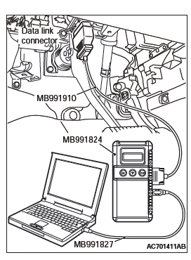
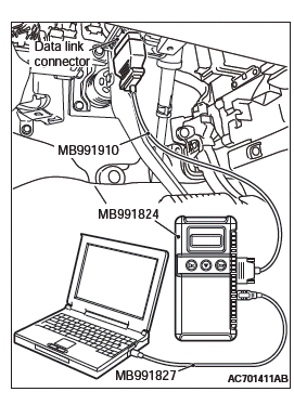
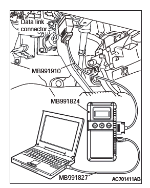
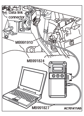
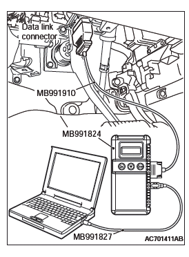
- MB991958 Scan Tool (M.U.T.-III Sub Assembly)
- MB991824: Vehicle Communication Interface (V.C.I.)
- MB991827 M.U.T.-III USB Cable
- MB991910 M.U.T.-III Main Harness A (Vehicles with CAN communication system)
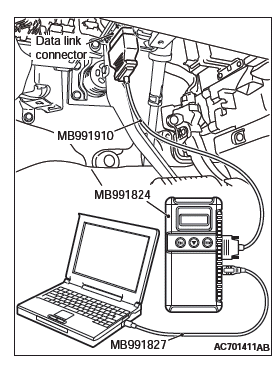
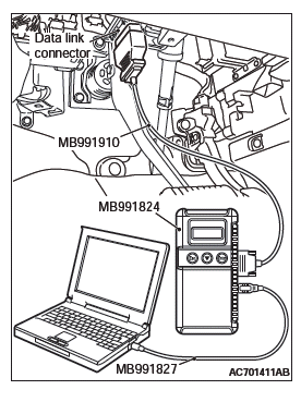
STEP 1. Using scan tool MB991958, diagnose the CAN bus line.
CAUTION To prevent damage to scan tool MB991958, always turn the ignition switch to the "LOCK" (OFF) position before connecting or disconnecting scan tool MB991958.
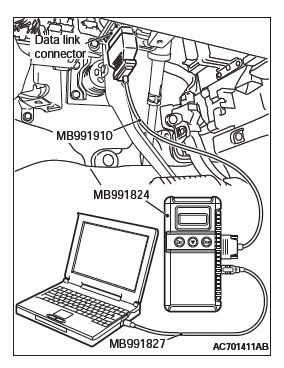
- Connect scan tool MB991958. Refer to "How to connect the scan tool".
- Turn the ignition switch to the "ON" position.
- Diagnose the CAN bus line.
- Turn the ignition switch to the "LOCK" (OFF) position.
Q: Is the CAN bus line found to be normal?
YES : Go to Step 2.
NO : Repair the CAN bus line.
STEP 2. Recheck for diagnostic trouble code.
Check again if the DTC is set.
- Erase the DTC.
- Turn the ignition switch to the "ON" position.
- Check if the DTC is set.
- Turn the ignition switch to the "LOCK" (OFF) position.
Q: Is the DTC set?
YES : Go to Step 3.
NO : There is an intermittent malfunction such as poor engaged connector(s) or open circuit.
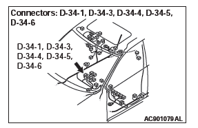
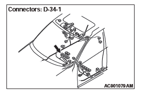
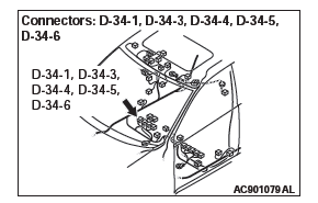
STEP 3. Check occupant classification-ECU connector D-34-1 and weight sensor connector D-34-3, D-34-4, D-34-5 or D-34-6 for loose, corroded or damaged terminals, or terminals pushed back in the connector.
Q: Is the check result normal?
YES : Go to Step 4.
NO : Replace the component(s) (Refer to GROUP 00E, Harness Connector Inspection).
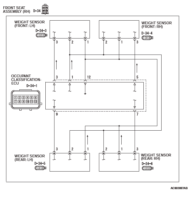
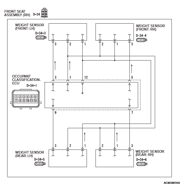
STEP 4. Check the wiring harness between occupant classification-ECU connector D-34-1 (terminal 3, 5, 7, and 9) and weight sensors D-34-3, D-34-4, D-34-5, and D-34-6 (terminal 3).
Q: Is the check result normal?
YES : Go to Step 5.
NO : The wiring harness may be damaged or the connector(s) may have loose, corroded or damaged terminals, or terminals pushed back in the connector.
Repair the wiring harness as necessary.
STEP 5. Recheck for diagnostic trouble code.
Check again if the DTC is set to the occupant classification- ECU.
- Erase the DTC.
- Turn the ignition switch from "LOCK" (OFF) position to "ON" position.
- Check if DTC is set.
- Turn the ignition switch to the "LOCK" (OFF) position.
Q: Is the DTC set?
YES : Replace the passenger seat cushion frame assembly.
NO : There is an intermittent malfunction such as poor engaged connector(s) or open circuit.
DTC B1B79: Passenger Seat Weight Sensor (ground side) Short-circuited
(front: LH)
DTC B1B7E: Passenger Seat Weight Sensor (ground side) Short-circuited (front: RH)
DTC B1B83: Passenger Seat Weight Sensor (ground side) Short-circuited (rear: LH)
DTC B1B88: Passenger Seat Weight Sensor (ground side) Short-circuited (rear: RH)
CAUTION If DTC B1B79, B1B7E, B1B83 or B1B88 is set in the occupant classification-ECU, always diagnose the CAN main bus lines.
CIRCUIT OPERATION
The load data from the weight sensor is classified with the occupant classification-ECU, and its classified information is send to SRS-ECU by CAN bus line. The SRS-ECU determines the air bag deployment based on this classified information, and controls the power supply circuit to the inflator.
DTC SET CONDITIONS
This DTC is see if the weight sensor wire are short-circuited to the ground.
TROUBLESHOOTING HINTS
- Disengaged wire harnesses or connector
- Short to the ground in the weight sensor harness
- Malfunction of the weight sensor
- Malfunction of the occupant classification-ECU
DIAGNOSIS
Required Special Tools:
- MB991958: Scan Tool (M.U.T.-III Sub Assembly)
- MB991824: Vehicle Communication Interface (V.C.I.)
- MB991827: M.U.T.-III USB Cable
- MB991910: M.U.T.-III Main Harness A (Vehicles with CAN Communication System)
STEP 1. Using scan tool MB991958, diagnose the CAN bus line.
CAUTION To prevent damage to scan tool MB991958, always turn the ignition switch to the "LOCK" (OFF) position before connecting or disconnecting scan tool MB991958.
- Connect scan tool MB991958. Refer to "How to connect the scan tool".
- Turn the ignition switch to the "ON" position.
- Diagnose the CAN bus line.
- Turn the ignition switch to the "LOCK" (OFF) position.
Q: Is the CAN bus line found to be normal?
YES : Go to Step 2.
NO : Repair the CAN bus line.
STEP 2. Recheck for diagnostic trouble code.
Check again if the DTC is set.
- Erase the DTC.
- Turn the ignition switch to the "ON" position.
- Check if the DTC is set.
- Turn the ignition switch to the "LOCK" (OFF) position.
Q: Is the DTC set?
YES : Go to Step 3.
NO : There is an intermittent malfunction such as poor engaged connector(s) or open circuit.
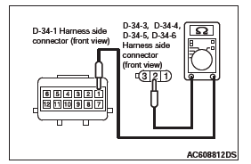
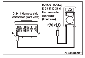
STEP 3. Measure the resistance at occupant classification-ECU connector D-34-1.
- Disconnect the connector D-34-1.
- Disconnect weight sensor connector D-34-3, D-34-4, D-34-5 or D-34-6.
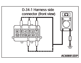
- Check for continuity between D-34-1 harness side
connector terminals 1, 3, 5, 7, 9 and body ground.
It should be open circuit.
Q: Is it open circuit?
YES : Go to Step 4.
NO : Repair the wiring harness between occupant classification-ECU connector D-34-1 terminals 3, 5, 9, 7 and weight sensor connector D-34-3, 4, 5, 6 terminals 3 (signal line) or occupant classification-ECU connector D-34-1 terminals 1 and weight sensor connector D-34-3 terminals 2 (power supply line). Then go to Step 4.
STEP 4. Recheck for diagnostic trouble code.
Check again if the DTC is set.
- Erase the DTC.
- Turn the ignition switch to the "ON" position.
- Check if the DTC is set.
- Turn the ignition switch to the "LOCK" (OFF) position.
Q: Is DTCs B1B79, B1B7E, B1B83, B1B88 set?
YES : Replace the passenger seat cushion frame assembly.
NO : There is an intermittent malfunction such as poor engaged connector(s) or open circuit (Refer to GROUP 00, How to Cope with Intermittent Malfunction).
DTC B1B7A: Passenger Seat Weight Sensor (power supply side)
Short-circuited or Open (front: LH)
DTC B1B7F: Passenger Seat Weight Sensor (power supply side) Short-circuited or
Open (front: RH)
DTC B1B84: Passenger Seat Weight Sensor (power supply side) Short-circuited or
Open (rear: LH)
DTC B1B89: Passenger Seat Weight Sensor (power supply side) Short-circuited or
Open (rear: RH)
CAUTION If DTC B1B7A, B1B7F, B1B84 or B1B89 is set in the occupant classification-ECU, always diagnose the CAN main bus lines.
CIRCUIT OPERATION
The load data from the weight sensor is classified with the occupant classification-ECU, and its classified information is send to SRS-ECU by CAN bus line. The SRS-ECU determines the air bag deployment based on this classified information, and controls the power supply circuit to the inflator.
DTC SET CONDITIONS
- This DTC is set if the weight sensor wire are short-circuited to the power supply.
- This DTC is set if the weight sensor wire are open circuit.
TROUBLESHOOTING HINTS
- Damaged wiring harnesses or connectors
- Short to the power supply in the weight sensor harness
- Open circuit in the weight sensor harness
- Malfunction of the weight sensor
- Malfunction of the occupant classification-ECU
DIAGNOSIS
Required Special Tools:
- MB991958: Scan Tool (M.U.T.-III Sub Assembly)
- MB991824: Vehicle Communication Interface (V.C.I.)
- MB991827: M.U.T.-III USB Cable
- MB991910: M.U.T.-III Main Harness A (Vehicles with CAN communication system)
STEP 1. Using scan tool MB991958, diagnose the CAN bus line.
CAUTION To prevent damage to scan tool MB991958, always turn the ignition switch to the "LOCK" (OFF) position before connecting or disconnecting scan tool MB991958.
- Connect scan tool MB991958. Refer to "How to connect the scan tool".
- Turn the ignition switch to the "ON" position.
- Diagnose the CAN bus line.
- Turn the ignition switch to the "LOCK" (OFF) position.
Q: Is the CAN bus line found to be normal?
YES : Go to Step 2.
NO : Repair the CAN bus line.
STEP 2. Recheck for diagnostic trouble code.
Check again if the DTC is set.
- Erase the DTC.
- Turn the ignition switch to the "ON" position.
- Check if the DTC is set.
- Turn the ignition switch to the "LOCK" (OFF) position.
Q: Is the DTCs set?
YES : Go to Step 3.
NO : There is an intermittent malfunction such as poor engaged connector(s) or open circuit.
STEP 3. Measure the voltage at occupant classification-ECU connector D-34-1.
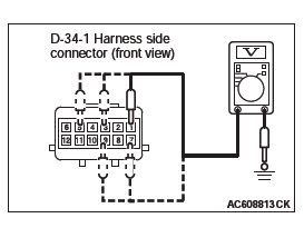
- Disconnect the connector D-34-1.
- Disconnect weight sensor connector D-34-3, D-34-4, D-34-5 or D-34-6.
- Turn the ignition switch to the "ON" position.
- Measure the voltage between terminals 1, 3, 5, 7, 9 and
body ground.
Voltage should measure 1 volt or less.
Q: Is the measured voltage within the specified range?
YES : Go to Step 4.
NO : Repair the wiring harness between occupant classification-ECU connector D-34-1 terminals 3, 5, 9, 7 and weight sensor connector D-34-3, 4, 5, 6 terminals 3 (signal line) or occupant classification-ECU connector D-34-1 terminals 1 and weight sensor connector D-34-3 terminals 2 (power supply line). Then go to Step 4.
STEP 4. Check the harness open circuit between occupant classification-ECU connector D-34-1 and weight sensor connector D-34-3, D-34-4, D-34-5 or D-34-6.
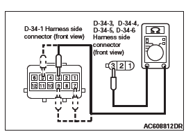
- Disconnect occupant classification-ECU connector D-34-1 and weight sensor connector D-34-3, D-34-4, D-34-5 or D-34-6.
- Check for continuity between the following terminals.
It should be less than 2 ohms.
- Occupant classification-ECU connector D-34-1 (terminal No.3) and the weight sensor connector D-34-3 (terminal No.3)
- Occupant classification-ECU connector D-34-1 (terminal No.5) and the weight sensor connector D-34-4 (terminal No.3)
- Occupant classification-ECU connector D-34-1 (terminal No.7) and the weight sensor connector D-34-6 (terminal No.3)
- Occupant classification-ECU connector D-34-1 (terminal No.9) and the weight sensor connector D-34-5 (terminal No.3)
- Occupant classification-ECU connector D-34-1 (terminal No.1) and the weight sensor connector D-34-3, D-34-4, D-34-5 and D-34-6 (terminal No.2)
- Occupant classification-ECU connector D-34-1 (terminal No.12) and weight sensor connector D-34-3, D-34-4, D-34-5 and D-34-6 (terminal No.1)
Q: Does continuity exist?
YES : Go to Step 5.
NO : Repair the harness wires between occupant classification-ECU connector D-34-1 and weight sensor connector D-34-3, D-34-4, D-34-5 and D-34-6.
Then go to Step 5.
STEP 5. Recheck for diagnostic trouble code.
Check again if the DTC is set.
- Erase the DTC.
- Turn the ignition switch to the "ON" position.
- Check if the DTC is set.
- Turn the ignition switch to the "LOCK" (OFF) position.
Q: Is DTCs B1B7A, B1B7F, B1B84, B1B89 set?
YES : Replace the passenger seat cushion frame assembly.
NO : There is an intermittent malfunction such as poor engaged connector(s) or open circuit.
DTC B1B8C: Driver Seat Slide Sensor Circuit Performance
Seat Slide Sensor Circuit
CAUTION If DTC B1B8C is set in the occupant classification- ECU, always diagnose the CAN main bus lines.
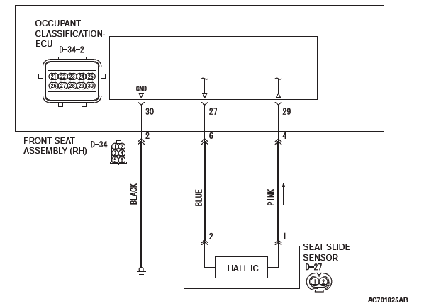
CIRCUIT OPERATION
- The seat slide sensor sets the current value Hi or Low determined by the seat position.
- The occupant classification-ECU determines the seat position according to the current value from the seat slide sensor.
DTC SET CONDITION
The DTC is set when the seat slide sensor output current is not within the specified range.
TROUBLESHOOTING HINTS
- The seat slide sensor may be defective.
- The wiring harness or connectors may have loose, corroded, or damaged terminals, or terminals pushed back in the connector
- Malfunction of the occupant classification-ECU
DIAGNOSIS
Required Special Tools:
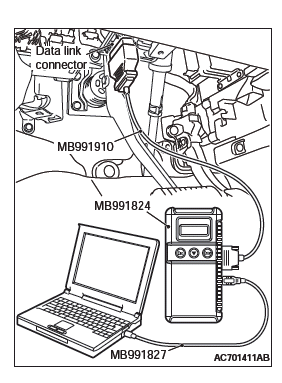
- MB991958 Scan Tool (M.U.T.-III Sub Assembly)
- MB991824: Vehicle Communication Interface (V.C.I.)
- MB991827 M.U.T.-III USB Cable
- MB991910 M.U.T.-III Main Harness A (Vehicles with CAN communication system)
STEP 1. Using scan tool MB991958, diagnose the CAN bus line.
CAUTION To prevent damage to scan tool MB991958, always turn the ignition switch to the "LOCK" (OFF) position before connecting or disconnecting scan tool MB991958.
- Connect scan tool MB991958. Refer to "How to connect the scan tool".
- Turn the ignition switch to the "ON" position.
- Diagnose the CAN bus line.
- Turn the ignition switch to the "LOCK" (OFF) position.
Q: Is the CAN bus line found to be normal?
YES : Go to Step 2.
NO : Repair the CAN bus line.
STEP 2. Recheck for diagnostic trouble code.
Check again if the DTC is set.
- Erase the DTC.
- Turn the ignition switch to the "ON" position.
- Check if the DTC is set.
- Turn the ignition switch to the "LOCK" (OFF) position.
Q: Is the DTC set?
YES : Go to Step 3.
NO : There is an intermittent malfunction such as poor engaged connector(s) or open circuit (Refer to GROUP 00, How to Cope with Intermittent Malfunction).
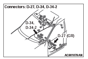
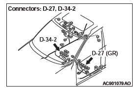
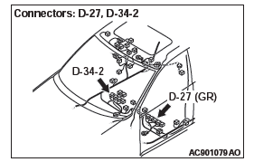
STEP 3. Check the occupant classification-ECU connector D-34-2, front seat assembly connector D-34 and seat slide sensor connector D-27 for loose, corroded or damaged terminals, or terminals pushed back in the connector.
Q: Is the occupant classification-ECU connector D-34-2, front seat assembly connector D-34 and seat slide sensor connector D-27 in good condition?
YES : Go to Step 4.
NO : Replace the component(s) (Refer to GROUP 00E, Harness Connector Inspection).
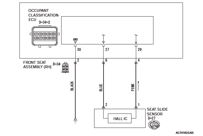
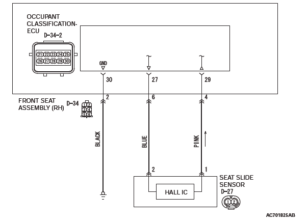
STEP 4. Check the harness for open circuit between occupant classification-ECU connector D-34-2 (terminal No.27 and 29) and the seat slide sensor connector D-27 (terminal No.2 and 1).
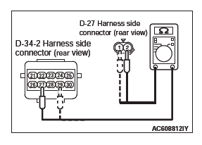
- Disconnect occupant classification-ECU connector D-34-2 and seat slide sensor connector D-27.
CAUTION Do not insert a test probe into the terminal from its front side directly, as the connector contact pressure may be weakened.
- Check for continuity between the following terminals. It should be less than 2 ohms.
- Occupant classification-ECU connector D-34-2 (terminal No.27) and the seat slide sensor connector D-27 (terminal No.2)
- Occupant classification-ECU connector D-34-2 (terminal No.29) and the seat slide sensor connector D-27 (terminal No.1)
Q: Does continuity exist?
YES : Go to Step 5.
NO : Repair the harness wires between occupant classification-ECU connector D-34-2 and seat slide sensor connector D-27.
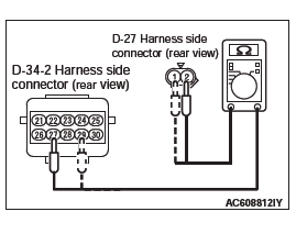
STEP 5. Check the seat slide sensor circuit. Measure the resistance at occupant classification-ECU connector D-34-2.
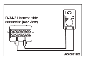
- Disconnect occupant classification connector-ECU connector D-34-2.
- Disconnect seat slide sensor connector D-27.
CAUTION Do not insert a test probe into the terminal from its front side directly, as the connector contact pressure may be weakened.
- Check for continuity between D-34-2 harness side
connector terminals 27 and 29.
It should be open circuit.
Q: Is it open circuit?
YES : Go to Step 6.
NO : Repair the harness wires between occupant classification-ECU connector D-34-2 and seat slide sensor connector D-27.
STEP 6. Check the harness for open circuit between occupant classification-ECU connector D-34-2.
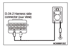
- Disconnect occupant classification-ECU connector D-34-2 and seat slide sensor connector D-27.
CAUTION Do not insert a test probe into the terminal from its front side directly, as the connector contact pressure may be weakened.
- Check for continuity between D-34-2 Occupant
classification-ECU connector terminals No.27, 29 and body
ground.
It should be open circuit.
Q: Is it open circuit?
YES : Go to Step 7
NO : Repair the harness wires between occupant classification-ECU connector D-34-2 and seat slide sensor connector D-27.
STEP 7. Recheck for diagnostic trouble code.
Check again if the DTC is set to the occupant classification- ECU.
- Erase the DTC.
- Turn the ignition switch from "LOCK" (OFF) position to "ON" position.
- Check if DTC is set.
- Turn the ignition switch to the "LOCK" (OFF) position.
Q: Is the DTC set?
YES : Replace the driver seat cushion frame assembly. Then go to Step 8.
NO : There is an intermittent malfunction such as poor engaged connector(s) or open circuit.
STEP 8. Recheck for diagnostic trouble code.
Check again if the DTC is set to the occupant classification- ECU.
- Erase the DTC.
- Turn the ignition switch from "LOCK" (OFF) position to "ON" position.
- Check if DTC is set.
- Turn the ignition switch to the "LOCK" (OFF) position.
Q: Is the DTC set?
YES : Replace the passenger seat cushion frame assembly.
NO : There is an intermittent malfunction such as poor engaged connector(s) or open circuit.
DTC B1B8D: Driver Seat Slide Sensor Open Circuit
Seat Slide Sensor Circuit
CAUTION If DTC B1B8D is set in the occupant classification- ECU, always diagnose the CAN main bus lines.
CIRCUIT OPERATION
- The seat slide sensor sets the current value Hi or Low determined by the seat position.
- The occupant classification-ECU determines the seat position according to the current value from the seat slide sensor.
DTC SET CONDITIONS
- This DTC is set if there is abnormal resistance
between the input terminals of the seat slide sensor.
The most likely causes for this code to be set are the followings:
- Open circuit in the seat slide sensor or harness
TROUBLESHOOTING HINTS
- Open circuit in the seat slide sensor circuit
- Disengaged seat slide sensor connector
- Improper connector contact
- Malfunction of the seat slide sensor
- Malfunction of the occupant classification-ECU
DIAGNOSIS
Required Special Tools:
- MB991958: Scan Tool (M.U.T.-III Sub Assembly)
- MB991824: Vehicle Communication Interface (V.C.I.)
- MB991827: M.U.T.-III USB Cable
- MB991910: M.U.T.-III Main Harness A (Vehicles with CAN communication system)
STEP 1. Using scan tool MB991958, diagnose the CAN bus line.
CAUTION To prevent damage to scan tool MB991958, always turn the ignition switch to the "LOCK" (OFF) position before connecting or disconnecting scan tool MB991958.
- Connect scan tool MB991958. Refer to "How to connect the scan tool".
- Turn the ignition switch to the "ON" position.
- Diagnose the CAN bus line.
- Turn the ignition switch to the "LOCK" (OFF) position.
Q: Is the CAN bus line found to be normal?
YES : Go to Step 2.
NO : Repair the CAN bus line.
STEP 2. Recheck for diagnostic trouble code.
Check again if the DTC is set.
- Erase the DTC.
- Turn the ignition switch to the "ON" position.
- Check if the DTC is set.
- Turn the ignition switch to the "LOCK" (OFF) position.
Q: Is the DTC set?
YES : Go to Step 3.
NO : There is an intermittent malfunction such as poor engaged connector(s) or open circuit.
STEP 3. Check the harness for open circuit between occupant classification-ECU connector D-34-2 (terminal No.27 and 29) and the seat slide sensor connector D-27 (terminal No.2 and 1).
- Disconnect occupant classification-ECU connector D-34-2 and seat slide sensor connector D-27.
CAUTION Do not insert a test probe into the terminal from its front side directly, as the connector contact pressure may be weakened.
- Check for continuity between the following terminals. It should be less than 2 ohms.
- Occupant classification-ECU connector D-34-2 (terminal No.27) and the seat slide sensor connector D-27 (terminal No.2)
- Occupant classification-ECU connector D-34-2 (terminal No.29) and the seat slide sensor connector D-27 (terminal No.1)
Q: Does continuity exist?
YES : Go to Step 4.
NO : Repair the harness wires between occupant classification-ECU connector D-34-2 and seat slide sensor connector D-27.
STEP 4. Recheck for diagnostic trouble code.
Check again if the DTC is set to the occupant classification- ECU.
- Erase the DTC.
- Turn the ignition switch from "LOCK" (OFF) position to "ON" position.
- Check if DTC is set.
- Turn the ignition switch to the "LOCK" (OFF) position.
Q: Is the DTC B1B8D set?
YES : Replace the driver seat cushion frame assembly. Then go to Step 5.
NO : There is an intermittent malfunction such as poor engaged connector(s) or open circuit (Refer to GROUP 00, How to Cope with Intermittent Malfunction).
STEP 5. Recheck for diagnostic trouble code.
Check again if the DTC is set to the occupant classification- ECU.
- Erase the DTC.
- Turn the ignition switch from "LOCK" (OFF) position to "ON" position.
- Check if DTC is set.
- Turn the ignition switch to the "LOCK" (OFF) position.
Q: Is the DTC set?
YES : Replace the passenger seat cushion frame assembly.
NO : There is an intermittent malfunction such as poor engaged connector(s) or open circuit (Refer to GROUP 00, How to Cope with Intermittent Malfunction).
DTC B1B8E: Driver Seat Slide Sensor Short (Power Supply Side) Circuit
Seat Slide Sensor Circuit
CAUTION If DTC B1B8E is set in the occupant classification- ECU, always diagnose the CAN main bus lines.
CIRCUIT OPERATION
- The seat slide sensor sets the current value Hi or Low determined by the seat position.
- The occupant classification determines the seat position according to the current value from the seat slide sensor.
DTC SET CONDITIONS
This DTC is set if there is short-circuited to the power supply between the input terminals of the seat slide sensor.
TROUBLESHOOTING HINTS
- Damaged wiring harnesses or connectors
- Short to the power supply in the seat slide sensor harness
- Malfunction of the seat slide sensor
- Malfunction of the occupant classification-ECU
DIAGNOSIS
Required Special Tools:
- MB991958: Scan Tool (M.U.T.-III Sub Assembly)
- MB991824: Vehicle Communication Interface (V.C.I.)
- MB991827: M.U.T.-III USB Cable
- MB991910: M.U.T.-III Main Harness A (Vehicles with CAN communication system)
STEP 1. Using scan tool MB991958, diagnose the CAN bus line.
CAUTION To prevent damage to scan tool MB991958, always turn the ignition switch to the "LOCK" (OFF) position before connecting or disconnecting scan tool MB991958.
- Connect scan tool MB991958. Refer to "How to connect the scan tool".
- Turn the ignition switch to the "ON" position.
- Diagnose the CAN bus line.
- Turn the ignition switch to the "LOCK" (OFF) position.
Q: Is the CAN bus line found to be normal?
YES : Go to Step 2.
NO : Repair the CAN bus line.
STEP 2. Recheck for diagnostic trouble code.
Check again if the DTC is set.
- Erase the DTC.
- Turn the ignition switch to the "ON" position.
- Check if the DTC is set.
- Turn the ignition switch to the "LOCK" (OFF) position.
Q: Is the DTC set?
YES : Go to Step 3.
NO : There is an intermittent malfunction such as poor engaged connector(s) or open circuit (Refer to GROUP 00, How to Cope with Intermittent Malfunction).
STEP 3. Check the seat slide sensor circuit. Measure the voltage at the occupant classification-ECU connector D-34-2.
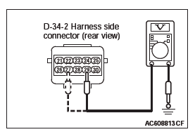
- Disconnect occupant classification connector-ECU connector D-34-2.
- Disconnect seat slide sensor connector D-27.
- Turn the ignition switch to the "ON" position.
CAUTION Do not insert a test probe into the terminal from its front side directly, as the connector contact pressure may be weakened.
- Measure the voltage between D-34-2 harness side
connector terminals 27, 29 and body ground.
Voltage should measure 1 volt or less.
Q: Is the measured voltage within the specified range?
YES : Go to Step 5.
NO : Go to Step 4.
STEP 4. Check the harness wires for short circuit to power supply between the occupant classification-ECU connector D-34-2 (terminal No.27 and 29) and seat slide sensor connector D-27 (terminal No.2 and 1).
Q: Are the harness wires between occupant classification-ECU connector D-34-2 (terminal No.27 and 29) and seat slide sensor connector D-27 (terminal No.2 and 1) in good condition?
YES : Go to Step 5.
NO : Repair the harness wires between the occupant classification-ECU connector D-34-2 and seat slide sensor connector D-27. Then go to Step 5.
STEP 5. Recheck for diagnostic trouble code.
Check again if the DTC is set to the occupant classification- ECU.
- Erase the DTC.
- Turn the ignition switch from "LOCK" (OFF) position to "ON" position.
- Check if DTC is set.
- Turn the ignition switch to the "LOCK" (OFF) position.
Q: Is the DTC B1B8E set?
YES : Replace the driver seat cushion frame assembly. Then go to Step 6.
NO : The procedure is complete.
STEP 6. Recheck for diagnostic trouble code.
Check again if the DTC is set to the occupant classification- ECU.
- Erase the DTC.
- Turn the ignition switch from "LOCK" (OFF) position to "ON" position.
- Check if DTC is set.
- Turn the ignition switch to the "LOCK" (OFF) position.
Q: Is the DTC set?
YES : Replace the passenger seat cushion frame assembly (Refer to GROUP 52A, Front Seat Assembly).
NO : There is an intermittent malfunction such as poor engaged connector(s) or open circuit (Refer to GROUP 00, How to Cope with Intermittent Malfunction).
DTC B1B91: Driver Seat Slide Sensor Configuration Mismatch
CAUTION If DTC B1B91 is set in the occupant classification- ECU, always diagnose the CAN main bus lines.
DTC SET CONDITIONS
These DTCs are set if there is an error in the coding data of the occupant classification-ECU.
TROUBLESHOOTING HINTS
Malfunction of occupant classification-ECU
DIAGNOSIS
Required Special Tools:
- MB991958 Scan Tool (M.U.T.-III Sub Assembly)
- MB991824: Vehicle Communication Interface (V.C.I.)
- MB991827 M.U.T.-III USB Cable
- MB991910 M.U.T.-III Main Harness A (Vehicles with CAN communication system)
STEP 1. Using scan tool MB991958, diagnose the CAN bus line.
CAUTION To prevent damage to scan tool MB991958, always turn the ignition switch to the "LOCK" (OFF) position before connecting or disconnecting scan tool MB991958.
- Connect scan tool MB991958. Refer to "How to connect the scan tool".
- Turn the ignition switch to the "ON" position.
- Diagnose the CAN bus line.
- Turn the ignition switch to the "LOCK" (OFF) position.
Q: Is the CAN bus line found to be normal?
YES : Go to Step 2.
NO : Repair the CAN bus line.
STEP 2. Recheck for diagnostic trouble code.
Check again if the DTC is set.
- Erase the DTC.
- Turn the ignition switch to the "ON" position.
- Check if the DTC is set.
- Turn the ignition switch to the "LOCK" (OFF) position.
Q: Is the DTC set?
YES : Replace the driver seat cushion frame assembly.
NO : There is an intermittent malfunction such as poor engaged connector(s) or open circuit (Refer to GROUP 00, How to Cope with Intermittent Malfunction).
DTC B1BA7: Occupant Classification System Verification Required
CAUTION If DTC B1BA7 is set in the occupant classification- ECU, always diagnose the CAN main bus lines.
CIRCUIT OPERATION
The load data from the weight sensor is classified with the occupant classification-ECU, and its classified information is send to SRS-ECU by CAN bus line. The SRS-ECU determines the air bag deployment based on this classified information, and controls the power supply circuit to the inflator.
DTC SET CONDITIONS
This DTC is set if a light impact is detected by the occupant classification-ECU.
TROUBLESHOOTING HINTS
- Malfunction of weight sensor
- Malfunction of the occupant classification-ECU
DIAGNOSIS
Required Special Tools:
- MB991958 Scan Tool (M.U.T.-III Sub Assembly)
- MB991824: Vehicle Communication Interface (V.C.I.)
- MB991827 M.U.T.-III USB Cable
- MB991910 M.U.T.-III Main Harness A (Vehicles with CAN communication system)
STEP 1. Using scan tool MB991958, diagnose the CAN bus line.
CAUTION To prevent damage to scan tool MB991958, always turn the ignition switch to the "LOCK" (OFF) position before connecting or disconnecting scan tool MB991958.
- Connect scan tool MB991958. Refer to "How to connect the scan tool".
- Turn the ignition switch to the "ON" position.
- Diagnose the CAN bus line.
- Turn the ignition switch to the "LOCK" (OFF) position.
Q: Is the CAN bus line found to be normal?
YES : Go to Step 2.
NO : Repair the CAN bus line.
STEP 2. Weight sensor check.
Q: Is the check result normal?
YES : Go to step 3.
NO : Replace the passenger seat cushion frame assembly.
STEP 3. Recheck for diagnostic trouble code.
Check again if the DTC is set.
- Erase the DTC.
- Turn the ignition switch to the "ON" position.
- Check if the DTC is set.
- Turn the ignition switch to the "LOCK" (OFF) position.
Q: Is the DTC B1BA7 set?
YES : Replace the passenger seat cushion frame assembly.
NO : There is an intermittent malfunction such as poor engaged connector(s) or open circuit (Refer to GROUP 00, How to Cope with Intermittent Malfunction).
DTC B1BA8: Occupant classification-ECU Out of Calibration/not Calibrated
CAUTION If DTC B1BA8 is set in the occupant classification- ECU, always diagnose the CAN main bus lines.
CIRCUIT OPERATION
The load data from the weight sensor is classified with the occupant classification-ECU, and its classified information is send to SRS-ECU by CAN bus line. The SRS-ECU determines the air bag deployment based on this classified information, and controls the power supply circuit to the inflator.
DTC SET CONDITION
This DTC is set when the 30 Kg (66 pounds) system and 0 Kg (0 pound) system have not been executed.
TROUBLESHOOTING HINTS
- Zero calibration not executed
- 30 Kg (66 pounds) system and 0 Kg (0 pound) system not executed
- Malfunction of the occupant classification-ECU
DIAGNOSIS
Required Special Tools:
- MB991958 Scan Tool (M.U.T.-III Sub Assembly)
- MB991824: Vehicle Communication Interface (V.C.I.)
- MB991827 M.U.T.-III USB Cable
- MB991910 M.U.T.-III Main Harness A (Vehicles with CAN communication system)
STEP 1. Using scan tool MB991958, diagnose the CAN bus line.
CAUTION To prevent damage to scan tool MB991958, always turn the ignition switch to the "LOCK" (OFF) position before connecting or disconnecting scan tool MB991958.
- Connect scan tool MB991958. Refer to "How to connect the scan tool".
- Turn the ignition switch to the "ON" position.
- Diagnose the CAN bus line.
- Turn the ignition switch to the "LOCK" (OFF) position.
Q: Is the CAN bus line found to be normal?
YES : Go to Step 2.
NO : Repair the CAN bus line.
STEP 2. Recheck for diagnostic trouble code.
Check again if the DTC is set.
- Erase the DTC.
- Turn the ignition switch to the "ON" position.
- Check if the DTC is set.
- Turn the ignition switch to the "LOCK" (OFF) position.
Q: Is the DTC B1BA7 set?
YES : After executing zero calibration of the occupant classification-ECU, execute 30 Kg (66 pounds) system and 0 Kg (0 pound) system. Then go to Step 3.
NO : There is an intermittent malfunction such as poor engaged connector(s) or open circuit (Refer to GROUP 00, How to Cope with Intermittent Malfunction).
STEP 3. Recheck for diagnostic trouble code.
Check again if the DTC is set to the occupant classification- ECU.
- Erase the DTC.
- Turn the ignition switch from "LOCK" (OFF) position to "ON" position.
- Check if DTC is set.
- Turn the ignition switch to the "LOCK" (OFF) position.
Q: Is the DTC set?
YES : Replace the passenger seat cushion frame assembly.
NO : There is an intermittent malfunction such as poor engaged connector(s) or open circuit (Refer to GROUP 00, How to Cope with Intermittent Malfunction).
READ NEXT:
 DTC B1BBA, B1BBC, B1BBD, B1C23, B1C24, B1C25, B1C26, B1CB2, B210D, B210E, B2206,
B2212, B2250, B2262
DTC B1BBA, B1BBC, B1BBD, B1C23, B1C24, B1C25, B1C26, B1CB2, B210D, B210E, B2206,
B2212, B2250, B2262
DTC B1BBA: Passenger Seat Weight Sensor Power Supply Circuit
CAUTION
If DTC B1BBA is set in the occupant classification-
ECU, always diagnose the CAN main bus
lines.
CIRCUIT OPERATION
The load data fr
DTC U0020, U0021, U0022, U0023, U0024, U0025, U0026, U0141, U0151, U0155, U0164,
U0168, U0184, U0195, U0245, U1419, U141A, U141B, U141C, U1423
DTC U0020: CAN-B Bus Off Performance
DTC U0021: CAN-B Bus(H1) Circuit Open
DTC U0022: CAN-B Bus(H1) Shorted to Circuit Ground
DTC U0023: CAN-B Bus(H1) Shorted to Circuit Power Supply
DTC U0024: CAN-B
Post-collision Diagnosis
To inspect and service the SRS after a collision (whether or not
the air bags have deployed), perform the following steps.
SRS-ECU MEMORY CHECK
Required Special Tool:
MB991958: Scan Tool (M.U.T.-III
SEE MORE:
General Information, Service Precautions
General Information
CAN, an abbreviation for Controller Area Network, is
an ISO-certified international standard for a serial
multiplex communication protocol*. A communication
circuit employing the CAN protocol connects each
electric control module (ECU), and sensor data can
be shared among, which
CVT
General Information
F1CJA, W1CJA model has been established.
TRANSAXLE
The transaxle consists of the torque converter and
gear train. The three-element, one-stage, two-phase
type torque converter with a built-in torque converter
clutch has been adopted. The gear train of F1CJA,
W1CJA transaxle cons
