Mitsubishi Outlander: DTC P0053, P0068, P0069, P0101, P0102, P0103, P0106, P0107, P0108
DTC P0053: Linear Air-Fuel Ratio Sensor Heater Resistance
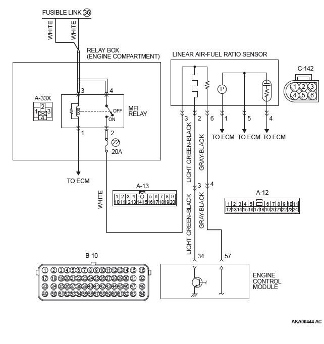
LINEAR AIR-FUEL RATIO SENSOR HEATER CIRCUIT
CIRCUIT OPERATION
- Power is supplied from the MFI relay (terminal No. 2) to the linear air-fuel ratio sensor heater.
- The ECM (terminal No. 34) controls continuity to the linear air-fuel ratio sensor heater by turning the power transistor in the ECM "ON" and "OFF".
TECHNICAL DESCRIPTION
- The ECM checks whether the heater current is within a specified range when the heater is energized.
DESCRIPTIONS OF MONITOR METHODS
Linear air-fuel ratio sensor heater current is out of specified range.
MONITOR EXECUTION
Continuous
ONITOR EXECUTION CONDITIONS (Other monitor and Sensor)
Other Monitor (There is no temporary DTC stored in memory for the item monitored below)
- Not applicable
Sensor (The sensor below is determined to be normal)
- Not applicable
DTC SET CONDITIONS
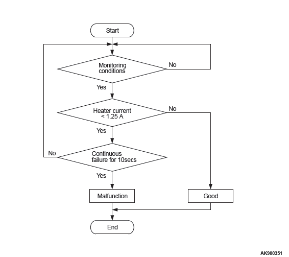
Logic Flow Chart
Check Conditions
- More than 220 seconds have passed since the engine starting sequence was completed.
- While the linear air-fuel ratio sensor heater is on.
- Battery positive voltage is between 11 and 16.5 volts.
- Intake air temperature is more than −10ºC (14ºF).
- On duty cycle of the linear air-fuel ratio sensor heater is between 3 and 97 percent.
Judgement Criterion
- The linear air-fuel ratio sensor heater current has continued to be lower than average 1.25 ampere for 10 seconds.
OBD-II DRIVE CYCLE PATTERN
- Refer to Diagnostic Function − OBD-II Drive Cycle − Pattern 22.
TROUBLESHOOTING HINTS (The most likely causes for this code to be set are:)
- Linear air-fuel ratio sensor circuit harness damage or connector damage.
- Linear air-fuel ratio sensor heater failed.
- ECM failed.
DIAGNOSIS
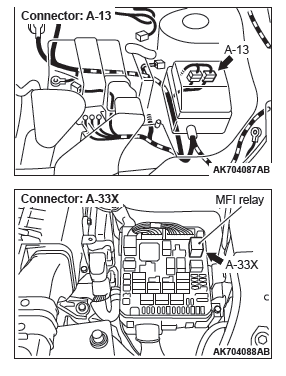
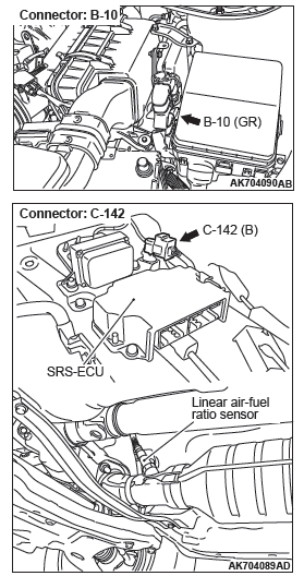
STEP 1. Check harness connector C-142 at linear air-fuel ratio sensor for damage.
Q: Is the harness connector in good condition?
YES : Go to Step 2.
NO : Repair or replace it. Refer to GROUP 00E, Harness Connector Inspection. Then go to Step 8.
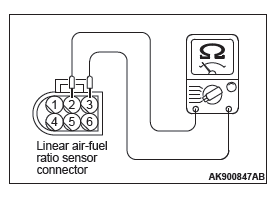
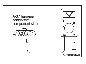
STEP 2. Check the linear air-fuel ratio sensor.
- Disconnect the linear air-fuel ratio sensor connector C-142.
- Measure the resistance between linear air-fuel ratio sensor connector terminal No. 2 and terminal No. 3.
Standard value: 2.3 − 4.2 ohms [at 20ºC (68ºF) ]
Q: Is the measured resistance between 2.3 and 4.2 ohms [at 20ºC (68ºF) ]?
YES : Go to Step 3.
NO : Replace the linear air-fuel ratio sensor. Then go to Step 8.
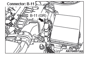
STEP 3. Check harness connector A-33X at the MFI relay for damage.
Q: Is the harness connector in good condition?
YES : Go to Step 4.
NO : Repair or replace it. Refer to GROUP 00E, Harness Connector Inspection. Then go to Step 8.
STEP 4. Check for harness damage between MFI relay connector A-33X (terminal No. 2) and linear air-fuel ratio sensor connector C-142 (terminal No. 3).
Q: Is the harness wire in good condition?
YES : Go to Step 5.
NO : Repair it. Then go to Step 8.
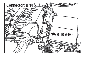
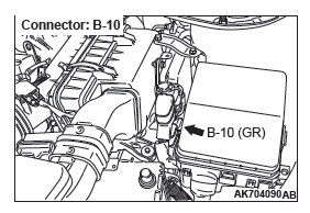
STEP 5. Check harness connector B-10 at ECM for damage.
Q: Is the harness connector in good condition?
YES : Go to Step 6.
NO : Repair or replace it. Refer to GROUP 00E, Harness Connector Inspection. Then go to Step 8.
STEP 6. Check for harness damage between linear air-fuel ratio sensor connector C-142 (terminal No. 2) and ECM connector B-10 (terminal No. 34).
NOTE: Check harness after checking intermediate connector A-13. If intermediate connector is damaged, repair or replace it.
Refer to GROUP 00E, Harness Connector Inspection.
Then go to Step 8.
Q: Is the harness wire in good condition?
YES : Go to Step 7.
NO : Repair it. Then go to Step 8.
STEP 7. Check the trouble symptoms.
- Carry out a test drive with the drive cycle pattern. Refer to Diagnostic Function − OBD-II Drive Cycle − Pattern 22.
- Check the diagnostic trouble code (DTC).
Q: Is DTC P0053 set?
YES : Replace the ECM. When the ECM is replaced, register the ID code. Refer to GROUP 42B, Diagnosis − ID Code Registration Judgment Table <Vehicles with KOS> or GROUP 42C, Diagnosis − ID Codes Registration Judgment Table <Vehicles with WCM>. Then go to Step 8.
NO : It can be assumed that this malfunction is intermittent.
Refer to GROUP 00, How to Use Troubleshooting/Inspection Service Points − How to Cope with Intermittent Malfunctions.
STEP 8. Test the OBD-II drive cycle.
- Carry out a test drive with the drive cycle pattern. Refer to Diagnostic Function − OBD-II Drive Cycle − Pattern 22.
- Check the diagnostic trouble code (DTC).
Q: Is DTC P0053 set?
YES : Retry the troubleshooting.
NO : The inspection is complete.
DTC P0068: Mass Airflow Sensor Plausibility
TECHNICAL DESCRIPTION
Compare the actual measurement of volumetric efficiency by a mass airflow sensor signal with volumetric efficiency estimated from a throttle position sensor (main or sub) signal.
MONITOR EXECUTION
Continuous
MONITOR EXECUTION CONDITIONS (Other monitor and Sensor)
Other Monitor (There is no temporary DTC stored in memory for the item monitored below)
- Not applicable
Sensor (The sensor below is determined to be normal)
- Not applicable
DTC SET CONDITIONS
Logic Flow Chart
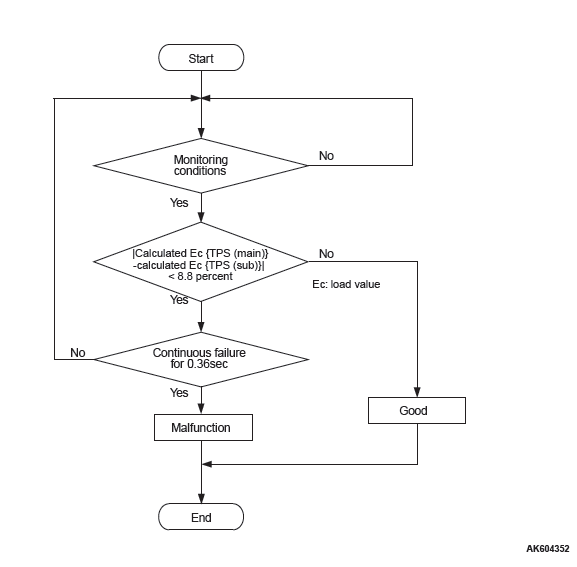
Check Conditions
- The plausibility error of the throttle position sensor (main) is detected.
- The plausibility error of the throttle position sensor (sub) is detected.
Judgment Criterion
- For 0.36 second, the difference between the volumetric efficiency estimated by the throttle position sensor (main) and the volumetric efficiency estimated by the throttle position sensor (sub) is 8.8 percent or less.
OBD-II DRIVE CYCLE PATTERN
Refer to Diagnostic Function − OBD-II Drive Cycle Pattern 17.
TROUBLESHOOTING HINTS (The most likely causes for this code to be set are:)
- Mass airflow sensor system failed.
- ECM failed.
DIAGNOSIS
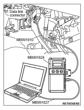
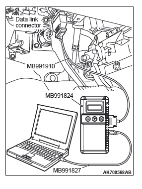
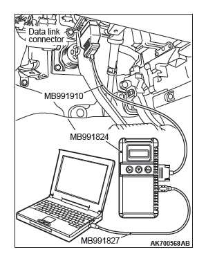
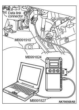
Required Special Tools:
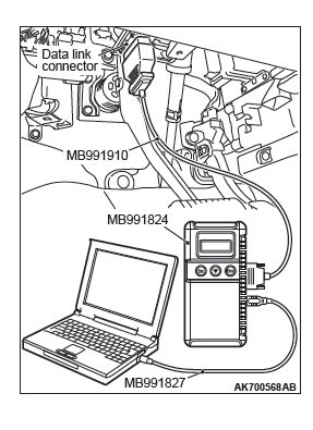
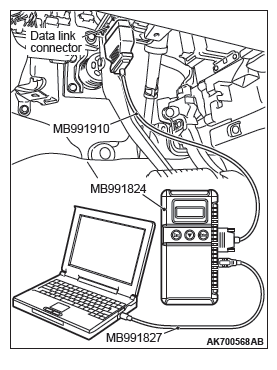
- MB991958: Scan Tool (M.U.T.-III Sub Assembly)
- MB991824: V.C.I.
- MB991827: USB Cable
- MB991910: Main Harness A
STEP 1. Using scan tool MB991958, read the diagnostic trouble code (DTC).
CAUTION To prevent damage to scan tool MB991958, always turn the ignition switch to the "LOCK" (OFF) position before connecting or disconnecting scan tool MB991958.
- Connect scan tool MB991958 to the data link connector.
- Turn the ignition switch to the "ON" position.
- Read the DTC.
- Turn the ignition switch to the "LOCK" (OFF) position.
Q: Is the diagnostic trouble code other than P0068 set?
YES : Refer to, Diagnostic Trouble Code Chart.
NO : Go to Step 2.
STEP 2. Using scan tool MB991958, check data list item 10: Mass Airflow Sensor.
- Start the engine and run at idle.
- Set scan tool MB991958 to the data reading mode for item 10, Mass Airflow Sensor.
- Warm up the engine to normal operating temperature: 80ºC
to 95ºC (176ºF to 203ºF).
- The standard value during idling should be between 1,350 and 1,670 millivolts.
- When the engine is revved, the mass airflow rate should increase according to the increase in engine speed.
- Turn the ignition switch to the "LOCK" (OFF) position.
Q: Is the sensor operating properly?
YES : Go to Step 3.
NO : Refer to, DTC P0101 − Mass Airflow Circuit Range/Performance Problem, DTC P0102 − Mass Airflow Circuit Low Input, DTC P0103 − Mass Airflow Circuit High Input.
STEP 3. Check the trouble symptoms.
- Carry out a test drive with the drive cycle pattern. Refer to Diagnostic Function − OBD-II Drive Cycle Pattern 17.
- Check the diagnostic trouble code (DTC).
Q: Is DTC P0068 set?
YES : Replace the ECM. When the ECM is replaced, register the ID code. Refer to GROUP 42B, Diagnosis − ID Code Registration Judgment Table <Vehicles with KOS> or GROUP 42C, Diagnosis − ID Codes Registration Judgment Table <Vehicles with WCM>. Then go to Step 4.
NO : It can be assumed that this malfunction is intermittent.
Refer to GROUP 00, How to Use Troubleshooting/Inspection Service Points − How to Cope with Intermittent Malfunctions.
STEP 4. Test the OBD-II drive cycle.
- Carry out a test drive with the drive cycle pattern. Refer to Diagnostic Function − OBD-II Drive Cycle Pattern 17.
- Check the diagnostic trouble code (DTC).
Q: Is DTC P0068 set?
YES : Retry the troubleshooting.
NO : The inspection is complete.
DTC P0069: Abnormal Correlation Between Manifold Absolute Pressure Sensor And Barometric Pressure Sensor
TECHNICAL DESCRIPTION
- The ECM detects abnormality in the sensor by comparing the manifold absolute pressure sensor output with the barometric pressure sensor output.
DESCRIPTIONS OF MONITOR METHODS
The ECM compares the manifold absolute pressure sensor output with the barometric pressure sensor output while the engine control relay is in "ON" position after the ignition switch is in "LOCK" (OFF) position. When the difference exceeds the specified value between them, the ECM determines whether the manifold absolute pressure sensor / the barometric pressure sensor has malfunction or not.
MONITOR EXECUTION
Continuous
MONITOR EXECUTION CONDITIONS (Other monitor and Sensor)
Other Monitor (There is no temporary DTC stored in memory for the item monitored below)
- Not applicable
Sensor (The sensor below is determined to be normal)
- Engine coolant temperature sensor
- Manifold absolute pressure sensor
DTC SET CONDITIONS
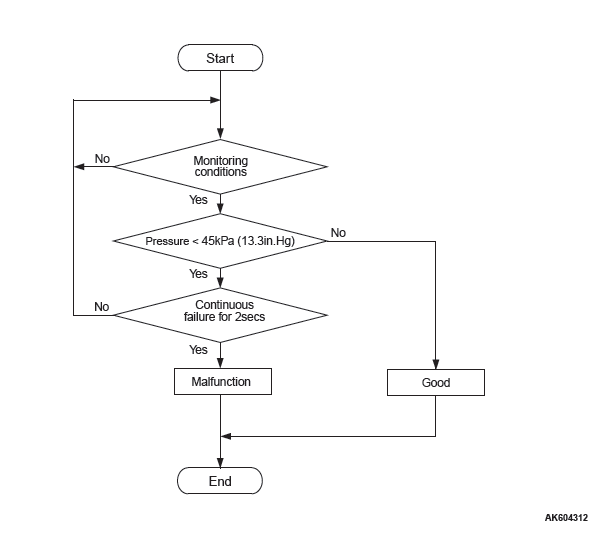
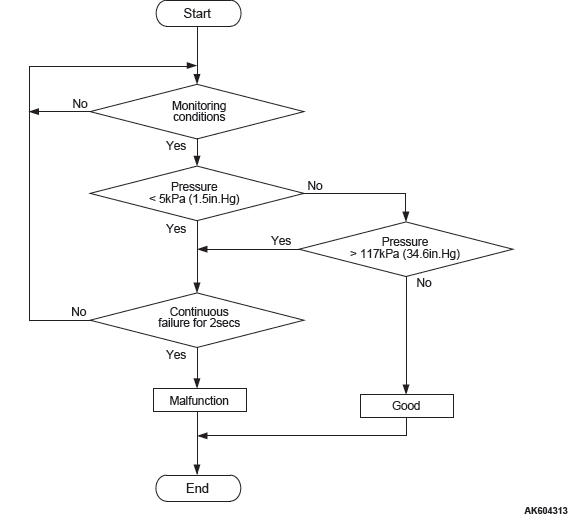
Logic Flow Chart
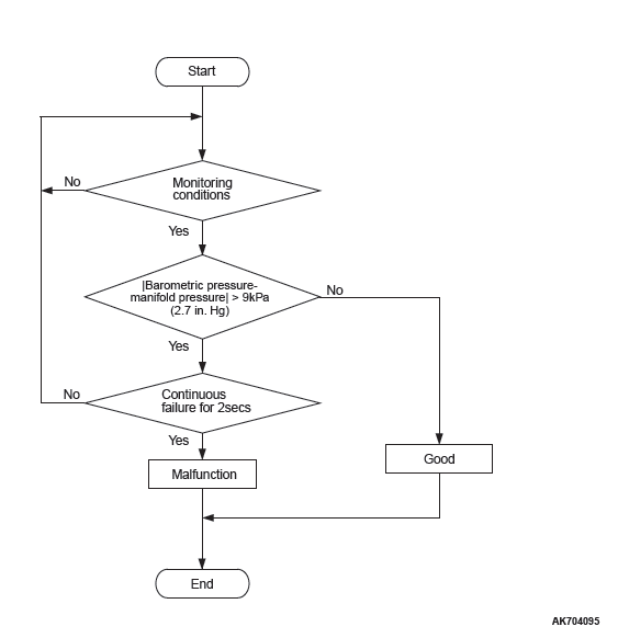
Check Conditions
- Ignition switch is in "LOCK" (OFF) position.
- After 2 seconds pass from the time when the engine is stopped.
- Engine coolant temperature is higher than 0ºC (32ºF).
Judgement Criterion
- Difference between manifold absolute pressure sensor output and barometric pressure sensor output is more than 9 kPa (2.7 in.Hg) for 2 seconds.
OBD-II DRIVE CYCLE PATTERN
None.
TROUBLESHOOTING HINTS (The most likely causes for this code to be set are:)
- Manifold absolute pressure sensor failed.
- Barometric pressure sensor failed.
- ECM failed.
DIAGNOSIS
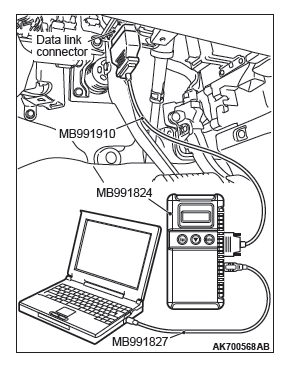
Required Special Tools
- MB991958: Scan tool (M.U.T.-III Sub Assembly)
- MB991824: V.C.I.
- MB991827: USB Cable
- MB991910: Main Harness A
STEP 1. Using scan tool MB991958, read the diagnostic trouble code (DTC).
CAUTION To prevent damage to scan tool MB991958, always turn the ignition switch to the "LOCK" (OFF) position before connecting or disconnecting scan tool MB991958.
- Connect scan tool MB991958 to the data link connector.
- Turn the ignition switch to the "ON" position.
- Set scan tool MB991958, read the DTC.
- Turn the ignition switch to the "LOCK" (OFF) position.
Q: Is the diagnostic trouble code other than P0069 set?
YES : Refer to, Diagnostic Trouble Code Chart.
NO : Go to Step 2.
STEP 2. Using scan tool MB991958, check data list item 8: Manifold Absolute Pressure Sensor.
- Turn the ignition switch to the "ON" position.
- Set scan tool MB991958 to the data reading mode for item
8, Manifold Absolute Pressure Sensor.
- When altitude is 0 m (0 foot), 101 kPa (29.8 in.Hg).
- When altitude is 600 m (1,969 feet), 95 kPa (28.1 in.Hg).
- When altitude is 1,200 m (3,937 feet), 88 kPa (26.0 in.Hg).
- When altitude is 1,800 m (5,906 feet), 81 kPa (23.9 in.Hg).
- Start the engine.
- When the engine is idling, 16 − 36 kPa (4.7 − 10.6 in.Hg).
- When the engine is suddenly revved, manifold absolute pressure varies.
- Turn the ignition switch to the "LOCK" (OFF) position.
Q: Is the sensor operating properly?
YES : Go to Step 3.
NO : Refer to, DTC P0106 − Manifold Absolute Pressure Circuit Range/Performance Problem, DTC P0107 − Manifold Absolute Pressure Circuit Low Input, DTC P0108 − Manifold Absolute Pressure Circuit High Input.
STEP 3. Using scan tool MB991958, read the diagnostic trouble code (DTC).
- Turn the ignition switch to the "ON" position.
- Erase the DTC.
- Start the engine.
- Turn the ignition switch to "LOCK" (OFF) position and then wait 2 seconds.
- Turn the ignition switch to the "ON" position.
- Set scan tool MB991958, read the DTC.
- Turn the ignition switch to the "LOCK" (OFF) position.
Q: Is DTC P0069 set?
YES : Replace the ECM. When the ECM is replaced, register the ID code. Refer to GROUP 42B, Diagnosis − ID Code Registration Judgment Table <Vehicles with KOS> or GROUP 42C, Diagnosis − ID Codes Registration Judgment Table <Vehicles with WCM>. Then go to Step 4.
NO : It can be assumed that this malfunction is intermittent.
Refer to GROUP 00, How to Use Troubleshooting/Inspection Service Points − How to Cope with Intermittent Malfunctions.
STEP 4. Using scan tool MB991958, read the diagnostic trouble code (DTC).
- Turn the ignition switch to the "ON" position.
- Erase the DTC.
- Start the engine.
- Turn the ignition switch to "LOCK" (OFF) position and then wait 2 seconds.
- Turn the ignition switch to the "ON" position.
- Set scan tool MB991958, read the DTC.
- Turn the ignition switch to the "LOCK" (OFF) position.
Q: Is DTC P0069 set?
YES : Retry the troubleshooting.
NO : The inspection is complete.
DTC P0101: Mass Airflow Circuit Range/Performance Problem
MASS AIRFLOW SENSOR CIRCUIT
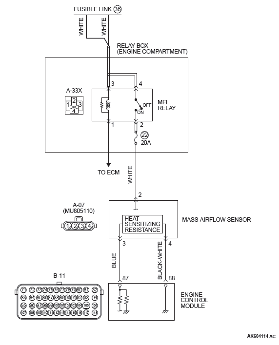

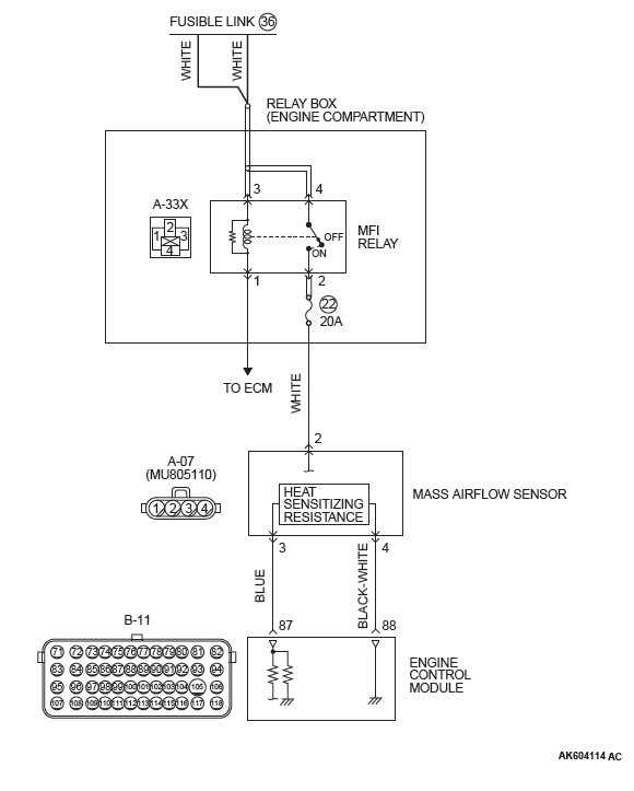
CIRCUIT OPERATION
- The mass airflow sensor power is supplied from the MFI relay (terminal No. 2), and the ground is provided on the ECM (terminal No. 88).
- A voltage that is according to the mass airflow rate is sent to the ECM (terminal No. 87) from the mass airflow sensor output terminal (terminal No.3).
TECHNICAL DESCRIPTION
- While the engine is running, the mass airflow sensor outputs electric current which corresponds to the mass airflow rate.
- The ECM converts the electric current into the voltage and checks whether the voltage is within a specified range while the engine is running.
DESCRIPTIONS OF MONITOR METHODS
Compare load value with mass airflow sensor output voltage.
MONITOR EXECUTION
Continuous
MONITOR EXECUTION CONDITIONS (Other monitor and Sensor)
Other Monitor (There is no temporary DTC stored in memory for the item monitored below)
- Not applicable
Sensor (The sensor below is determined to be normal)
- Throttle position sensor
DTC SET CONDITIONS <Range/Performance problem − high>
Logic Flow Chart
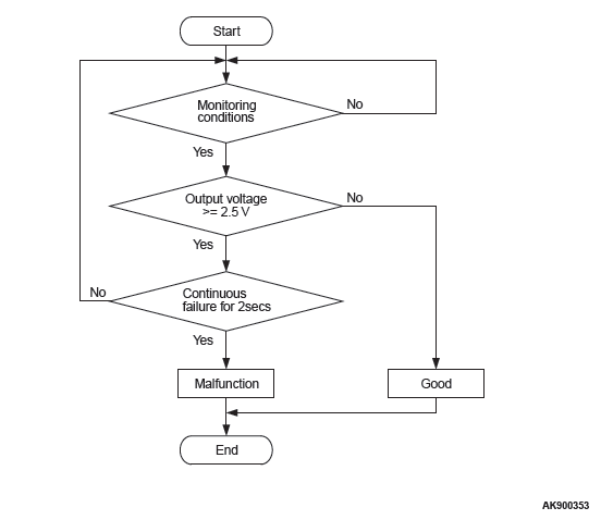
Check Conditions
- Throttle position sensor output voltage is 0.8 volt or lower.
- Mass airflow sensor output voltage is 4.9 volts (corresponding to an air flow rate of 295 g/sec) or lower.
Judgement Criterion
- Mass airflow sensor output voltage has continued to be 2.5 volts (corresponding to an air flow rate of 28 g/sec) or higher for 2 seconds.
DTC SET CONDITIONS <Range/Performance problem − low >
Logic Flow Chart
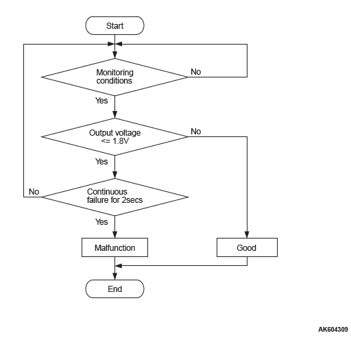
Check Conditions
- Engine speed is 1,500 r/min or more.
- Throttle position sensor output voltage is 1.5 volts or higher.
- Mass airflow sensor output voltage is 0.2 volt (corresponding to an air flow rate of 0 g/sec) or higher.
Judgement Criterion
- Mass airflow sensor output voltage has continued to be 1.8 volts (corresponding to an air flow rate of 8 g/sec) or lower for 2 seconds.
OBD-II DRIVE CYCLE PATTERN
- Refer to Diagnostic Function − OBD-II Drive Cycle − Pattern 7.
TROUBLESHOOTING HINTS (The most likely causes for this code to be set are:)
- Mass airflow sensor failed.
- Mass airflow sensor circuit harness damage, or connector damage.
- ECM failed.
DIAGNOSIS
Required Special Tools:
- MB991958: Scan tool (M.U.T.-III Sub Assembly)
- MB991824: V.C.I.
- MB991827: USB Cable
- MB991910: Main Harness A
STEP 1. Using scan tool MB991958, check data list item 10: Mass Airflow Sensor.
CAUTION To prevent damage to scan tool MB991958, always turn the ignition switch to the "LOCK" (OFF) position before connecting or disconnecting scan tool MB991958.
- Connect scan tool MB991958 to the data link connector.
- Start the engine and run at idle.
- Set scan tool MB991958 to the data reading mode for item 10, Mass Airflow Sensor.
- Warm up the engine to normal operating temperature: 80ºC
to 95ºC (176ºF to 203ºF).
- The standard value during idling should be between 1,350 and 1,670 millivolts.
- When the engine is revved, the mass airflow rate should increase according to the increase in engine speed.
- Turn the ignition switch to the "LOCK" (OFF) position.
Q: Is the sensor operating properly?
YES : It can be assumed that this malfunction is intermittent.
Refer to GROUP 00, How to Use Troubleshooting/Inspection Service Points − How to Cope with Intermittent Malfunctions.
NO : Go to Step 2.
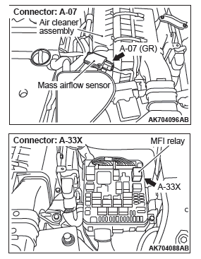
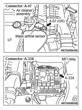
STEP 2. Check harness connector A-07 at mass airflow sensor and harness connector A-33X at MFI relay for damage.
Q: Is the harness connector in good condition?
YES : Go to Step 3.
NO : Repair or replace it. Refer to GROUP 00E, Harness Connector Inspection. Then go to Step 8.
STEP 3. Check for harness damage between MFI relay connector A-33X (terminal No. 2) and mass airflow sensor connector A-07 (terminal No. 2).
Q: Is the harness wire in good condition? YES : Go to Step 4.
NO : Repair it. Then go to Step 8.
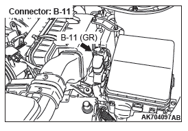
STEP 4. Check harness connector B-10 at ECM for damage.
Q: Is the harness connector in good condition?
YES : Go to Step 5.
NO : Repair or replace it. Refer to GROUP 00E, Harness Connector Inspection. Then go to Step 8.
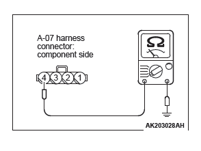
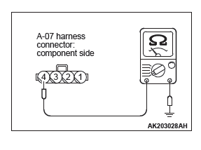
STEP 5. Check the continuity at mass airflow sensor harness side connector A-07.
- Disconnect the connector A-07 and measure at the harness side.
- Check for the continuity between terminal No. 4 and
ground.
- Continuity (2 ohms or less)
Q: Does continuity exist?
YES : Go to Step 6.
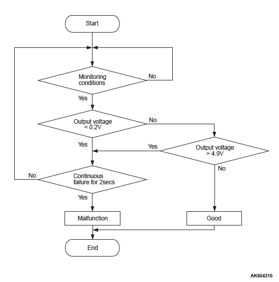
NO : Repair harness wire between mass airflow sensor connector A-07 (terminal No. 4) and ECM connector B-11 (terminal No. 88) because of harness damage.
Then go to Step 8.
STEP 6. Check for harness damage between mass airflow sensor connector A-07 (terminal No. 3) and ECM connector B-11 (terminal No. 87).
Q: Is the harness wire in good condition?
YES : Go to Step 7.
NO : Repair it. Then go to Step 8.
STEP 7. Replace the mass airflow sensor.
- Replace the mass airflow sensor.
- Carry out a test drive with the drive cycle pattern. Refer to Diagnostic Function − OBD-II Drive Cycle − Pattern 7.
- Check the diagnostic trouble code (DTC).
Q: Is DTC P0101 set?
YES : Replace the ECM. When the ECM is replaced, register the ID code. Refer to GROUP 42B, Diagnosis − ID Code Registration Judgment Table <Vehicles with KOS> or GROUP 42C, Diagnosis − ID Codes Registration Judgment Table <Vehicles with WCM>. Then go to Step 8.
NO : The inspection is complete.
STEP 8. Test the OBD-II drive cycle.
- Carry out a test drive with the drive cycle pattern. Refer to Diagnostic Function − OBD-II Drive Cycle − Pattern 7.
- Check the diagnostic trouble code (DTC).
Q: Is DTC P0101 set?
YES : Retry the troubleshooting.
NO : The inspection is complete.
DTC P0102: Mass Airflow Circuit Low Input
MASS AIRFLOW SENSOR CIRCUIT
CIRCUIT OPERATION
- The mass airflow sensor power is supplied from the MFI relay (terminal No. 2), and the ground is provided on the ECM (terminal No. 88).
- A voltage that is according to the mass airflow rate is sent to the ECM (terminal No. 87) from the mass airflow sensor output terminal (terminal No. 3).
TECHNICAL DESCRIPTION
- While the engine is running, the mass airflow sensor outputs voltage which corresponds to the mass airflow rate.
- The ECM checks whether the voltage output by the mass airflow sensor while the engine is running is within a specified range.
DESCRIPTIONS OF MONITOR METHODS
Mass airflow sensor output voltage is out of specified range.
MONITOR EXECUTION
Continuous
MONITOR EXECUTION CONDITIONS (Other monitor and Sensor)
Other Monitor (There is no temporary DTC stored in memory for the item monitored below)
- Not applicable
Sensor (The sensor below is determined to be normal)
- Not applicable
DTC SET CONDITIONS
Logic Flow Chart
Check Condition
- 3 seconds or more have passed since the ignition switch was turned to "ON" position.
Judgement Criterion
- Mass airflow sensor output voltage has continued to be lower than 0.2 volt (corresponding to an air flow rate of 0 g/sec) for 2 seconds.
OBD-II DRIVE CYCLE PATTERN
- Refer to Diagnostic Function − OBD-II Drive Cycle − Pattern 23.
TROUBLESHOOTING HINTS (The most likely causes for this code to be set are:)
- Mass airflow sensor failed.
- Open or shorted mass airflow sensor circuit, or connector damage.
- ECM failed.
DIAGNOSIS
Required Special Tools:
- MB991958: Scan tool (M.U.T.-III Sub Assembly)
- MB991824: V.C.I.
- MB991827: USB Cable
- MB991910: Main Harness A
- MB992110: Power Plant ECU Check Harness
STEP 1. Using scan tool MB991958, check data list item 10: Mass Airflow Sensor.
CAUTION To prevent damage to scan tool MB991958, always turn the ignition switch to the "LOCK" (OFF) position before connecting or disconnecting scan tool MB991958.
- Connect scan tool MB991958 to the data link connector.
- Start the engine and run at idle.
- Set scan tool MB991958 to the data reading mode for item 10, Mass Airflow Sensor.
- Warm up the engine to normal operating temperature: 80ºC
to 95ºC (176ºF to 203ºF).
- The standard value during idling should be between 1,350 and 1,670 millivolts.
- When the engine is revved, the mass airflow rate should increase according to the increase in engine speed.
- Turn the ignition switch to the "LOCK" (OFF) position.
Q: Is the sensor operating properly?
YES : It can be assumed that this malfunction is intermittent.
Refer to GROUP 00, How to Use Troubleshooting/Inspection Service Points − How to Cope with Intermittent Malfunctions.
NO : Go to Step 2.
STEP 2. Check harness connector A-07 at mass airflow sensor for damage.
Q: Is the harness connector in good condition?
YES : Go to Step 3.
NO : Repair or replace it. Refer to GROUP 00E, Harness Connector Inspection. Then go to Step 10.
STEP 3. Measure the power supply voltage at mass airflow sensor harness side connector A-07.
- Disconnect the connector A-07 and measure at the harness side.
- Turn the ignition switch to the "ON" position.
- Measure the voltage between terminal No. 2 and ground.
- Voltage should be battery positive voltage.
- Turn the ignition switch to the "LOCK" (OFF) position.
Q: Is battery positive voltage (approximately 12 volts) present?
YES : Go to Step 5.
NO : Go to Step 4.
STEP 4. Check harness connector A-33X at MFI relay for damage.
Q: Is the harness connector in good condition?
YES : Repair harness wire between MFI relay connector A-33X (terminal No. 2) and mass airflow sensor connector A-07 (terminal No. 2) because of open circuit or short circuit to ground. Then go to Step 10.
NO : Repair or replace it. Refer to GROUP 00E, Harness Connector Inspection. Then go to Step 10.
STEP 5. Check harness connector B-10 at ECM for damage.
Q: Is the harness connector in good condition?
YES : Go to Step 6.
NO : Repair or replace it. Refer to GROUP 00E, Harness Connector Inspection. Then go to Step 10.
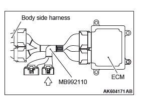
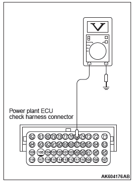
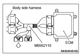
STEP 6. Measure the sensor output voltage at ECM connector B-11 by using power plant ECU check harness special tool MB992110.
- Disconnect all ECM connectors. Connect the power plant ECU check harness special tool MB992110 between the separated connectors.
- Start the engine.
- Measure the voltage between terminal No. 87 and ground.
- When the engine is revved, voltage should be increase in response to revving.
Q: Is the measured voltage normal?
YES : Go to Step 9.
NO : Go to Step 7.
STEP 7. Check for open circuit and short circuit to ground between mass airflow sensor connector A-07 (terminal No. 3) and ECM connector B-11 (terminal No. 87).
Q: Is the harness wire in good condition?
YES : Go to Step 8.
NO : Repair it. Then go to Step 10.
STEP 8. Replace the mass airflow sensor.
- Replace the mass airflow sensor.
- Carry out a test drive with the drive cycle pattern. Refer to Diagnostic Function − OBD-II Drive Cycle − Pattern 23.
- Check the diagnostic trouble code (DTC).
Q: Is DTC P0102 set?
YES : Replace the ECM. When the ECM is replaced, register the ID code. Refer to GROUP 42B, Diagnosis − ID Code Registration Judgment Table <Vehicles with KOS> or GROUP 42C, Diagnosis − ID Codes Registration Judgment Table <Vehicles with WCM>. Then go to Step 10.
NO : The inspection is complete.
STEP 9. Using scan tool MB991958, check data list item 10: Mass Airflow Sensor.
- Start the engine and run at idle.
- Set scan tool MB991958 to the data reading mode for item 10, Mass Airflow Sensor.
- Warm up the engine to normal operating temperature: 80ºC
to 95ºC (176ºF to 203ºF).
- The standard value during idling should be between 1,350 and 1,670 millivolts.
- When the engine is revved, the mass airflow rate should increase according to the increase in engine speed.
- Turn the ignition switch to the "LOCK" (OFF) position.
Q: Is the sensor operating properly?
YES : It can be assumed that this malfunction is intermittent.
Refer to GROUP 00, How to Use Troubleshooting/Inspection Service Points − How to Cope with Intermittent Malfunctions.
NO : Replace the ECM. When the ECM is replaced, register the ID code. Refer to GROUP 42B, Diagnosis − ID Code Registration Judgment Table <Vehicles with KOS> or GROUP 42C, Diagnosis − ID Codes Registration Judgment Table <Vehicles with WCM>. Then go to Step 10.
STEP 10. Test the OBD-II drive cycle.
- Carry out a test drive with the drive cycle pattern. Refer to Diagnostic Function − OBD-II Drive Cycle − Pattern 23.
- Check the diagnostic trouble code (DTC).
Q: Is DTC P0102 set?
YES : Retry the troubleshooting.
NO : The inspection is complete.
DTC P0103: Mass Airflow Circuit High Input
MASS AIRFLOW SENSOR CIRCUIT


CIRCUIT OPERATION
- The mass airflow sensor power is supplied from the MFI relay (terminal No. 2), and the ground is provided on the ECM (terminal No. 88).
- A voltage that is according to the mass airflow rate is sent to the ECM (terminal No. 87) from the mass airflow sensor output terminal (terminal No.3).
TECHNICAL DESCRIPTION
- While the engine is running, the mass airflow sensor outputs voltage which corresponds to the mass airflow rate.
- The ECM checks whether the voltage output by the mass airflow sensor while the engine is running is within a specified range.
DESCRIPTIONS OF MONITOR METHODS
Mass airflow sensor output voltage is out of specified range.
MONITOR EXECUTION
Continuous
MONITOR EXECUTION CONDITIONS (Other monitor and Sensor)
Other Monitor (There is no temporary DTC stored in memory for the item monitored below)
- Not applicable
Sensor (The sensor below is determined to be normal)
- Not applicable
DTC SET CONDITIONS
Logic Flow Chart
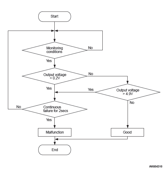
Check Condition
- 3 seconds or more have passed since the ignition switch was turned to "ON" position.
Judgement Criterion
- Mass airflow sensor output voltage has continued to be higher than 4.9 volts (corresponding to an air flow rate of 295 g/sec) for 2 seconds.
OBD-II DRIVE CYCLE PATTERN
- Refer to Diagnostic Function − OBD-II Drive Cycle − Pattern 23.
TROUBLESHOOTING HINTS (The most likely causes for this code to be set are:)
- Mass airflow sensor failed.
- Open mass airflow sensor circuit, or connector damage.
- ECM failed.
DIAGNOSIS
Required Special Tools:
- MB991958: Scan tool (M.U.T.-III Sub Assembly)
- MB991824: V.C.I.
- MB991827: USB Cable
- MB991910: Main Harness A
STEP 1. Using scan tool MB991958, check data list item 10: Mass Airflow Sensor.
CAUTION To prevent damage to scan tool MB991958, always turn the ignition switch to the "LOCK" (OFF) position before connecting or disconnecting scan tool MB991958.
- Connect scan tool MB991958 to the data link connector.
- Start the engine and run at idle.
- Set scan tool MB991958 to the data reading mode for item 10, Mass Airflow Sensor.
- Warm up the engine to normal operating temperature: 80ºC
to 95ºC (176ºF to 203ºF).
- The standard value during idling should be between 1,350 and 1,670 millivolts.
- When the engine is revved, the mass airflow rate should increase according to the increase in engine speed.
- Turn the ignition switch to the "LOCK" (OFF) position.
Q: Is the sensor operating properly?
YES : It can be assumed that this malfunction is intermittent.
Refer to GROUP 00, How to Use Troubleshooting/Inspection Service Points − How to Cope with Intermittent Malfunctions.
NO : Go to Step 2.
STEP 2. Check harness connector A-07 at mass airflow sensor for damage.
Q: Is the harness connector in good condition?
YES : Go to Step 3.
NO : Repair or replace it. Refer to GROUP 00E, Harness Connector Inspection. Then go to Step 8.
STEP 3. Check the continuity at mass airflow sensor harness side connector A-07.
- Disconnect the connector A-07 and measure at the harness side.
- Check for the continuity between terminal No. 4 and
ground.
- Continuity (2 ohms or less)
Q: Does continuity exist?
YES : Go to Step 7.
NO : Go to Step 4.
STEP 4. Check harness connector B-11 at ECM for damage.
Q: Is the harness connector in good condition?
YES : Go to Step 5.
NO : Repair or replace it. Refer to GROUP 00E, Harness Connector Inspection. Then go to Step 8.
STEP 5. Check for open circuit between mass airflow sensor connector A-07 (terminal No. 4) and ECM connector B-11 (terminal No. 88).
Q: Is the harness wire in good condition?
YES : Go to Step 6.
NO : Repair it. Then go to Step 8.
STEP 6. Using scan tool MB991958, check data list item 10: Mass Airflow Sensor.
- Start the engine and run at idle.
- Set scan tool MB991958 to the data reading mode for item 10, Mass Airflow Sensor.
- Warm up the engine to normal operating temperature: 80ºC
to 95ºC (176ºF to 203ºF).
- The standard value during idling should be between 1,350 and 1,670 millivolts.
- When the engine is revved, the mass airflow rate should increase according to the increase in engine speed.
- Turn the ignition switch to the "LOCK" (OFF) position.
Q: Is the sensor operating properly?
YES : It can be assumed that this malfunction is intermittent.
Refer to GROUP 00, How to Use Troubleshooting/Inspection Service Points − How to Cope with Intermittent Malfunctions.
NO : Replace the ECM. When the ECM is replaced, register the ID code. Refer to GROUP 42B, Diagnosis − ID Code Registration Judgment Table <Vehicles with KOS> or GROUP 42C, Diagnosis − ID Codes Registration Judgment Table <Vehicles with WCM>. Then go to Step 8.
STEP 7. Check harness connector B-11 at ECM for damage.
Q: Is the harness connector in good condition?
YES : Replace the mass airflow sensor. Then go to Step 8.
NO : Repair or replace it. Refer to GROUP 00E, Harness Connector Inspection. Then go to Step 8.
STEP 8. Test the OBD-II drive cycle.
- Carry out a test drive with the drive cycle pattern. Refer to Diagnostic Function − OBD-II Drive Cycle − Pattern 23.
- Check the diagnostic trouble code (DTC).
Q: Is DTC P0103 set?
YES : Retry the troubleshooting.
NO : The inspection is complete.
DTC P0106: Manifold Absolute Pressure Circuit Range/Performance Problem
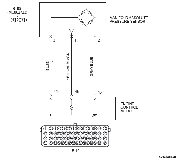
MANIFOLD ABSOLUTE PRESSURE SENSOR CIRCUIT
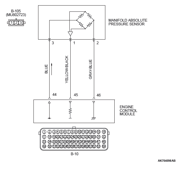
CIRCUIT OPERATION
- A 5-volt voltage is supplied to the manifold absolute pressure sensor power terminal (terminal No.3) from the ECM (terminal No. 44). The ground terminal (terminal No. 2) is grounded with ECM (terminal No. 46).
- A voltage that is proportional to the intake manifold pressure is sent to the ECM (terminal No. 45) from the manifold absolute pressure sensor output terminal (terminal No. 1).
TECHNICAL DESCRIPTION
- The manifold absolute pressure sensor outputs a voltage which corresponds to the intake manifold pressure.
- The ECM checks whether this voltage is within a specified range.
DESCRIPTIONS OF MONITOR METHODS
Compare load value with manifold absolute pressure sensor output voltage.
MONITOR EXECUTION
Continuous
MONITOR EXECUTION CONDITIONS (Other monitor and Sensor)
Other Monitor (There is no temporary DTC stored in memory for the item monitored below)
- Not applicable
Sensor (The sensor below is determined to be normal)
- Engine coolant temperature sensor
- Throttle position sensor
- Mass airflow sensor
- Intake air temperature sensor
- Barometric pressure sensor
DTC SET CONDITIONS <Range/Performance problem − high input>
Logic Flow Chart
Check Conditions
- 8 minutes or more have passed since the engine starting sequence was completed, when the engine coolant temperature at engine start is 0ºC (32ºF) or lower.
- Engine speed is between 500 r/min and 1,500 r/min.
- Throttle position sensor output voltage is 0.8 volt or lower.
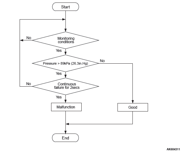
Judgement Criterion
- Manifold absolute pressure sensor output voltage has continued to be 3.5 volts [corresponding to a manifold absolute pressure of 89 kPa (26.3 in.Hg) ] or higher for 2 seconds.
DTC SET CONDITIONS <Range/Performance problem − low input>
Logic Flow Chart
Check Conditions
- 8 minutes or more have passed since the engine starting sequence was completed, when the engine coolant temperature at engine start is 0ºC (32ºF) or lower.
- Engine speed is 1,500 r/min or higher.
- Throttle position sensor output voltage is 3.5 volts or higher.
Judgement Criterion
- Manifold absolute pressure sensor output voltage has continued to be 1.8 volts [corresponding to a manifold absolute pressure of 45 kPa (13.3 in.Hg) ] or lower for 2 seconds.
OBD-II DRIVE CYCLE PATTERN
- Refer to Diagnostic Function − OBD-II Drive Cycle − Pattern 7.
TROUBLESHOOTING HINTS (The most likely causes for this code to be set are:)
- Manifold absolute pressure sensor failed.
- Mass airflow sensor circuit harness damage, or connector damage.
- ECM failed.
DIAGNOSIS
Required Special Tools:
- MB991958: Scan Tool (M.U.T.-III Sub Assembly)
- MB991824: V.C.I.
- MB991827: USB Cable
- MB991910: Main Harness A
- MB992110: Power Plant ECU Check Harness
STEP 1. Using scan tool MB991958, check data list item 8: Manifold Absolute Pressure Sensor.
CAUTION To prevent damage to scan tool MB991958, always turn the ignition switch to the "LOCK" (OFF) position before connecting or disconnecting scan tool MB991958.
- Connect scan tool MB991958 to the data link connector.
- Turn the ignition switch to the "ON" position.
- Set scan tool MB991958 to the data reading mode for item
8, Manifold Absolute Pressure Sensor.
- When altitude is 0 m (0 foot), 101 kPa (29.8 in.Hg).
- When altitude is 600 m (1,969 feet), 95 kPa (28.1 in.Hg).
- When altitude is 1,200 m (3,937 feet), 88 kPa (26.0 in.Hg).
- When altitude is 1,800 m (5,906 feet), 81 kPa (23.9 in.Hg).
- Start the engine.
- When the engine is idling, 16 − 36 kPa (4.7 − 10.6 in.Hg).
- When the engine is suddenly revved, manifold absolute pressure varies.
- Turn the ignition switch to the "LOCK" (OFF) position.
Q: Is the sensor operating properly?
YES : It can be assumed that this malfunction is intermittent.
Refer to GROUP 00, How to Use Troubleshooting/Inspection Service Points − How to Cope with Intermittent Malfunctions.
NO : Go to Step 2.
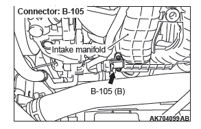
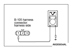
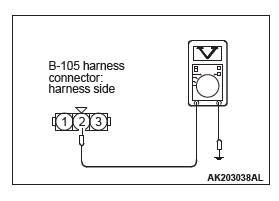
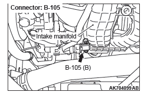
STEP 2. Measure the sensor output voltage at manifold absolute pressure sensor connector B-105 by backprobing.
- Do not disconnect the connector B-105.
- Turn the ignition switch to the "ON" position.
- Measure the voltage between terminal No. 1 and ground by
backprobing.
- When altitude is 0 m (0 foot), voltage should be between 3.8 and 4.2 volts.
- When altitude is 600 m (1,969 feet), voltage should be between 3.5 and 3.9 volts.
- When altitude is 1,200 m (3,937 feet), voltage should be between 3.3 and 3.7 volts.
- When altitude is 1,800 m (5,906 feet), voltage should be between 3.0 and 3.4 volts.
- Turn the ignition switch to the "LOCK" (OFF) position.
Q: Is the measured voltage normal?
YES : Go to Step 10.
NO : Go to Step 3.
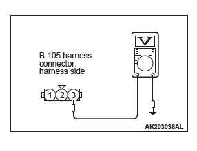
STEP 3. Measure the sensor supply voltage at manifold absolute pressure sensor connector B-105 by backprobing.
- Do not disconnect the connector B-105.
- Turn the ignition switch to the "ON" position.
- Measure the voltage between terminal No. 3 and ground by
backprobing.
- Voltage should be between 4.9 and 5.1 volts.
- Turn the ignition switch to the "LOCK" (OFF) position.
Q: Is the measured voltage between 4.9 and 5.1 volts?
YES : Go to Step 6.
NO : Go to Step 4.
STEP 4. Check harness connector B-105 at the manifold absolute pressure sensor and harness connector B-10 at ECM for damage.
Q: Is the harness connector in good condition?
YES : Go to step 5.
NO : Repair or replace it. Refer to GROUP 00E, Harness Connector Inspection. Then go to Step 13.
STEP 5. Check for harness damage between manifold absolute pressure sensor connector B-105 (terminal No. 3) and ECM connector B-10 (terminal No. 44).
Q: Is the harness wire in good condition?
YES : Go to Step 12.
NO : Repair it. Then go to Step 13.
STEP 6. Measure the ground voltage at manifold absolute pressure sensor connector B-105 by backprobing.
- Do not disconnect the connector B-105.
- Turn the ignition switch to the "ON" position.
- Measure the voltage between terminal No. 2 and ground by
backprobing.
- Voltage should be 0.5 volt or less.
- Turn the ignition switch to the "LOCK" (OFF) position.
Q: Is the measured voltage 0.5 volt or less?
YES : Go to Step 9.
NO : Go to Step 7.
STEP 7. Check harness connector B-105 at the manifold absolute pressure sensor and harness connector B-10 at ECM for damage.
Q: Is the harness connector in good condition?
YES : Go to Step 8.
NO : Repair or replace it. Refer to GROUP 00E, Harness Connector Inspection. Then go to Step 13.
STEP 8. Check for harness damage between manifold absolute pressure sensor connector B-105 (terminal No. 2) and ECM connector B-10 (terminal No. 46).
Q: Is the harness wire in good condition?
YES : Go to Step 12.
NO : Repair it. Then go to Step 13.
STEP 9. Check harness connector B-105 at manifold absolute pressure sensor for damage.
Q: Is the harness connector in good condition?
YES : Replace the manifold absolute pressure sensor. Then go to Step 13.
NO : Repair or replace it. Refer to GROUP 00E, Harness Connector Inspection. Then go to Step 13.
STEP 10. Check harness connector B-105 at the manifold absolute pressure sensor and harness connector B-10 at ECM for damage.
Q: Is the harness connector in good condition?
YES : Go to Step 11.
NO : Repair or replace it. Refer to GROUP 00E, Harness Connector Inspection. Then go to Step 13.
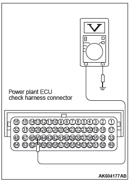
STEP 11. Measure the sensor output voltage at ECM connector B-10 by using power plant ECU check harness special tool MB992110.
- Disconnect all ECM connectors. Connect the power plant ECU check harness special tool MB992110 between the separated connectors.
- Turn the ignition switch to the "ON" position.
- Measure the voltage between terminal No. 45 and ground.
- When altitude is 0 m (0 foot), voltage should be between 3.8 and 4.2 volts.
- When altitude is 600 m (1,969 feet), voltage should be between 3.5 and 3.9 volts.
- When altitude is 1,200 m (3,937 feet), voltage should be between 3.3 and 3.7 volts.
- When altitude is 1,800 m (5,906 feet), voltage should be between 3.0 and 3.4 volts.
- Turn the ignition switch to the "LOCK" (OFF) position.
Q: Is the measured voltage normal?
YES : Go to Step 12.
NO : Repair harness wire between manifold absolute pressure sensor connector B-105 (terminal No. 1) and ECM connector B-10 (terminal No. 45) because of harness damage. Then go to Step 13.
STEP 12. Using scan tool MB991958, check data list item 8: Manifold Absolute Pressure Sensor.
- Turn the ignition switch to the "ON" position.
- Set scan tool MB991958 to the data reading mode for item
8, Manifold Absolute Pressure Sensor.
- When altitude is 0 m (0 foot), 101 kPa (29.8 in.Hg).
- When altitude is 600 m (1,969 feet), 95 kPa (28.1 in.Hg).
- When altitude is 1,200 m (3,937 feet), 88 kPa (26.0 in.Hg).
- When altitude is 1,800 m (5,906 feet), 81 kPa (23.9 in.Hg).
- Start the engine.
- When the engine is idling, 16 − 36 kPa (4.7 − 10.6 in.Hg).
- When the engine is suddenly revved, manifold absolute pressure varies.
- Turn the ignition switch to the "LOCK" (OFF) position.
Q: Is the sensor operating properly?
YES : It can be assumed that this malfunction is intermittent.
Refer to GROUP 00, How to Use Troubleshooting/Inspection Service Points − How to Cope with Intermittent Malfunctions.
NO : Replace the ECM. When the ECM is replaced, register the ID code. Refer to GROUP 42B, Diagnosis − ID Code Registration Judgment Table <Vehicles with KOS> or GROUP 42C, Diagnosis − ID Codes Registration Judgment Table <Vehicles with WCM>. Then go to Step 13.
STEP 13. Test the OBD-II drive cycle.
- Carry out a test drive with the drive cycle pattern. Refer to Diagnostic Function − OBD-II Drive Cycle − Pattern 7.
- Check the diagnostic trouble code (DTC).
Q: Is DTC P0106 set?
YES : Retry the troubleshooting.
NO : The inspection is complete.
DTC P0107: Manifold Absolute Pressure Circuit Low Input
MANIFOLD ABSOLUTE PRESSURE SENSOR CIRCUIT
CIRCUIT OPERATION
- A 5-volt voltage is supplied to the manifold absolute pressure sensor power terminal (terminal No.3) from the ECM (terminal No. 44). The ground terminal (terminal No. 2) is grounded with ECM (terminal No. 46).
- A voltage that is proportional to the intake manifold pressure is sent to the ECM (terminal No. 45) from the manifold absolute pressure sensor output terminal (terminal No. 1).
TECHNICAL DESCRIPTION
- The manifold absolute pressure sensor outputs a voltage which corresponds to the intake manifold pressure.
- The ECM checks whether this voltage is within a specified range.
DESCRIPTIONS OF MONITOR METHODS Manifold absolute pressure sensor output voltage is out of specified range.
MONITOR EXECUTION
Continuous
MONITOR EXECUTION CONDITIONS (Other monitor and Sensor)
Other Monitor (There is no temporary DTC stored in memory for the item monitored below)
- Not applicable
Sensor (The sensor below is determined to be normal)
- Engine coolant temperature sensor
- Throttle position sensor
- Mass airflow sensor
- Intake air temperature sensor
- Barometric pressure sensor
DTC SET CONDITIONS
Logic Flow Chart
Check Conditions
- 8 minutes or more have passed since the engine starting sequence was completed, when the engine coolant temperature at engine start is 0ºC (32ºF) or lower.
- Volumetric efficiency is higher than 20 percent.
Judgement Criterion
- Manifold absolute pressure sensor output voltage has continued to be 0.2 volt [corresponding to a manifold absolute pressure of 5 kPa (1.5 in.Hg) ] or lower for 2 seconds.
OBD-II DRIVE CYCLE PATTERN
- Refer to Diagnostic Function − OBD-II Drive Cycle − Pattern 7.
TROUBLESHOOTING HINTS (The most likely causes for this code to be set are:)
- Manifold absolute pressure sensor failed.
- Open or shorted manifold absolute pressure sensor circuit, or connector damage.
- ECM failed.
DIAGNOSIS
Required Special Tools:
- MB991958: Scan Tool (M.U.T.-III Sub Assembly)
- MB991824: V.C.I.
- MB991827: USB Cable
- MB991910: Main Harness A
- MB992110: Power Plant ECU Check Harness
STEP 1. Using scan tool MB991958, check data list item 8: Manifold Absolute Pressure Sensor.
CAUTION To prevent damage to scan tool MB991958, always turn the ignition switch to the "LOCK" (OFF) position before connecting or disconnecting scan tool MB991958.
- Connect scan tool MB991958 to the data link connector.
- Turn the ignition switch to the "ON" position.
- Set scan tool MB991958 to the data reading mode for item
8, Manifold Absolute Pressure Sensor.
- When altitude is 0 m (0 foot), 101 kPa (29.8 in.Hg).
- When altitude is 600 m (1,969 feet), 95 kPa (28.1 in.Hg).
- When altitude is 1,200 m (3,937 feet), 88 kPa (26.0 in.Hg).
- When altitude is 1,800 m (5,906 feet), 81 kPa (23.9 in.Hg).
- Start the engine.
- When the engine is idling, 16 − 36 kPa (4.7 − 10.6 in.Hg).
- When the engine is suddenly revved, manifold absolute pressure varies.
- Turn the ignition switch to the "LOCK" (OFF) position.
Q: Is the sensor operating properly?
YES : It can be assumed that this malfunction is intermittent.
Refer to GROUP 00, How to Use Troubleshooting/Inspection Service Points − How to
READ NEXT:
 DTC P0111, P0112, P0113, P0116, P0117, P0118, P0121, P0122, P0123, P0125, P0128,
P0130, P0131
DTC P0111, P0112, P0113, P0116, P0117, P0118, P0121, P0122, P0123, P0125, P0128,
P0130, P0131
DTC P0111: Intake Air Temperature Circuit Range/Performance Problem
INTAKE AIR TEMPERATURE SENSOR CIRCUIT
CIRCUIT OPERATION
Approximately 5 volts are applied to the intake air
temperature sensor
Fuel Supply
General Information
This fuel system is designed with consideration for
global environment protection to ensure safety at a
collision, reduce weight, and improve reliability and
quality. This system h
Intake and Exhaust
Service Specifications
Special Tools
Intake and Exhaust
Diagnosis
INTRODUCTION
Intake leaks usually create driveability issues that
are not obviously related to the intake system.
Exhaust leaks or
SEE MORE:
General Information
NOTE: In this manual, F.A.S.T.-key (Free-hand
Advanced Security Transmitter) is described as Keyless
Operation System (KOS).
The keyless operation system (KOS) enables the
driver to unlock all the doors and the liftgate by just
pulling the front door outside handle or operating the
liftgate lock rel
Cleaning the exterior of your vehicle
If the following is left on your vehicle, it may cause corrosion, discolouration
and stains, wash the vehicle as soon as possible.
● Seawater, road deicing products.
● Soot and dust, iron powder from factories, chemical substance (acids, alkalis,
coal-tar, etc.).
● Droppings
