Mitsubishi Outlander: DTC B1BBA, B1BBC, B1BBD, B1C23, B1C24, B1C25, B1C26, B1CB2, B210D, B210E, B2206, B2212, B2250, B2262
DTC B1BBA: Passenger Seat Weight Sensor Power Supply Circuit
CAUTION If DTC B1BBA is set in the occupant classification- ECU, always diagnose the CAN main bus lines.
CIRCUIT OPERATION
The load data from the weight sensor is classified with the occupant classification-ECU, and its classified information is send to SRS-ECU by CAN bus line. The SRS-ECU determines the air bag deployment based on this classified information, and controls the power supply circuit to the inflator.
DTC SET CONDITIONS
This DTC is set if the weight sensor power supply line is defective.
TROUBLESHOOTING HINTS
- The weight sensor may be defective.
- The occupant classification-ECU may be defective.
- The wiring harness or connectors may have loose, corroded, or damaged terminals, or terminals pushed back in the connector
DIAGNOSIS
Required Special Tools:
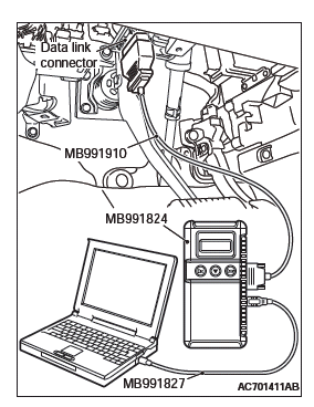
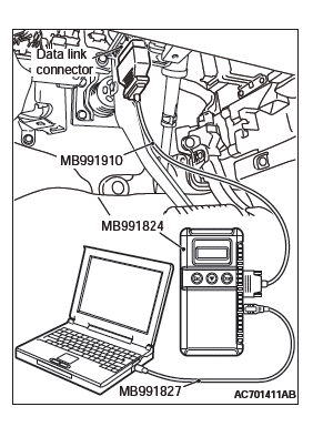
- MB991958 Scan Tool (M.U.T.-III Sub Assembly)
- MB991824: Vehicle Communication Interface (V.C.I.)
- MB991827 M.U.T.-III USB Cable
- MB991910 M.U.T.-III Main Harness A (Vehicles with CAN communication system)
STEP 1. Using scan tool MB991958, diagnose the CAN bus line.
CAUTION To prevent damage to scan tool MB991958, always turn the ignition switch to the "LOCK" (OFF) position before connecting or disconnecting scan tool MB991958.

- Connect scan tool MB991958. Refer to "How to connect the scan tool".
- Turn the ignition switch to the "ON" position.
- Diagnose the CAN bus line.
- Turn the ignition switch to the "LOCK" (OFF) position.
Q: Is the CAN bus line found to be normal?
YES : Go to Step 2.
NO : Repair the CAN bus line.
STEP 2. Recheck for diagnostic trouble code.
Check again if the DTC is set.
- Erase the DTC.
- Turn the ignition switch to the "ON" position.
- Check if the DTC is set.
- Turn the ignition switch to the "LOCK" (OFF) position.
Q: Is the DTC set?
YES : Go to Step 3.
NO : There is an intermittent malfunction such as poor engaged connector(s) or open circuit (Refer to GROUP 00, How to Cope with Intermittent Malfunction).
STEP 3. Using scan tool MB991958,read the occupant classification-ECU diagnostic trouble code.
Check if the DTC B210D or B210E is set the occupant classification- ECU.
Q: Is the DTC B1B78, B1B7D, B1B82 or B1B87 set?
YES : Diagnose the occupant classification-ECU.
NO : Replace the passenger seat cushion frame assembly.
DTC B1BBC: Occupant Classification System Negative System Weight
CAUTION If DTC B1BBC is set in the occupant classification- ECU, always diagnose the CAN main bus lines.
CIRCUIT OPERATION
The load data from the weight sensor is classified with the occupant classification-ECU, and its classified information is send to SRS-ECU by CAN bus line. The SRS-ECU determines the air bag deployment based on this classified information, and controls the power supply circuit to the inflator.
DTC SET CONDITION
This DTC is set if the passenger seat weight is −15 Kg (−35 pound) or less.
TROUBLESHOOTING HINTS
An object is caught in between the passenger seat and floor.
DIAGNOSIS
Required Special Tools:
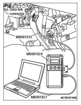
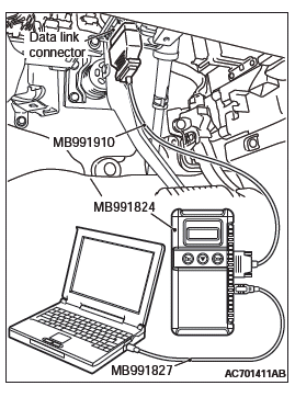
- MB991958 Scan Tool (M.U.T.-III Sub Assembly)
- MB991824: Vehicle Communication Interface (V.C.I.)
- MB991827 M.U.T.-III USB Cable
- MB991910 M.U.T.-III Main Harness A (Vehicles with CAN communication system)
STEP 1. Check for an object caught in between the passenger seat and floor.
Q: Is the check result normal?
YES : Go to Step 2.
NO : It corrects.
STEP 2. Using scan tool MB991958, diagnose the CAN bus line.
CAUTION To prevent damage to scan tool MB991958, always turn the ignition switch to the "LOCK" (OFF) position before connecting or disconnecting scan tool MB991958.
- Connect scan tool MB991958. Refer to "How to connect the scan tool".
- Turn the ignition switch to the "ON" position.
- Diagnose the CAN bus line.
- Turn the ignition switch to the "LOCK" (OFF) position.
Q: Is the CAN bus line found to be normal?
YES : Go to Step 3.
NO : Repair the CAN bus line.
STEP 3. Recheck for diagnostic trouble code.
Check again if the DTC is set.
- Erase the DTC.
- Turn the ignition switch to the "ON" position.
- Check if the DTC is set.
- Turn the ignition switch to the "LOCK" (OFF) position.
Q: Is the DTC B1BBC set?
YES : Replace the passenger seat cushion frame assembly.
NO : There is an intermittent malfunction such as poor engaged connector(s) or open circuit (Refer to GROUP 00, How to Cope with Intermittent Malfunction).
DTC B1BBD: Occupant Classification-ECU Current Configuration table Unprogrammed
CAUTION If DTC B1BBD is set in the occupant classification- ECU, always diagnose the CAN main bus lines.
DTC SET CONDITIONS
The DTC is set if the check error occurs in the coding data of the occupant classification-ECU.
TROUBLESHOOTING HINTS
- Zero calibration not executed
- The occupant Classification-ECU may be defective.
DIAGNOSIS
Required Special Tools:
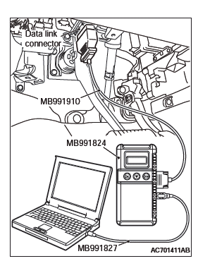
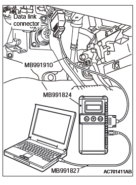
- MB991958 Scan Tool (M.U.T.-III Sub Assembly)
- MB991824: Vehicle Communication Interface (V.C.I.)
- MB991827 M.U.T.-III USB Cable
- MB991910 M.U.T.-III Main Harness A (Vehicles with CAN communication system)
STEP 1. Using scan tool MB991958, diagnose the CAN bus line.
CAUTION To prevent damage to scan tool MB991958, always turn the ignition switch to the "LOCK" (OFF) position before connecting or disconnecting scan tool MB991958.
- Connect scan tool MB991958. Refer to "How to connect the scan tool".
- Turn the ignition switch to the "ON" position.
- Diagnose the CAN bus line.
- Turn the ignition switch to the "LOCK" (OFF) position.
Q: Is the CAN bus line found to be normal?
YES : Go to Step 2.
NO : Repair the CAN bus line.
STEP 2. Recheck for diagnostic trouble code.
Check again if the DTC is set the occupant classification-ECU.
- Zero calibration of occupant classification -ECU
- Erase the DTC.
- Turn the ignition switch to the "ON" position.
- Check if the DTC is set.
- Turn the ignition switch to the "LOCK" (OFF) position.
Q: Is the DTC set?
YES : Replace the passenger seat cushion frame assembly (Refer to GROUP 52A, Front Seat Assembly).
NO : There is an intermittent malfunction such as poor engaged connector(s) or open circuit (Refer to GROUP 00, How to Cope with Intermittent Malfunction).
DTC B1C23: Passenger Seat Weight Sensor (front: LH) Configuration
Mismatch
DTC B1C24: Passenger Seat Weight Sensor (front: RH) Configuration Mismatch
DTC B1C25: Passenger Seat Weight Sensor (rear: LH) Configuration Mismatch
DTC B1C26: Passenger Seat Weight Sensor (rear: RH) Configuration Mismatch
CAUTION If DTC B1C23, B1C24 B1C25, B1C26 is set in the occupant classification-ECU, always diagnose the CAN main bus lines.
DTC SET CONDITIONS
The DTC is set if the weight sensor serial No. of the coding data in the occupant classification-ECU does not match the serial No. sent from the weight sensor.
TROUBLESHOOTING HINTS
- Zero calibration not executed
DIAGNOSIS
Required Special Tools:
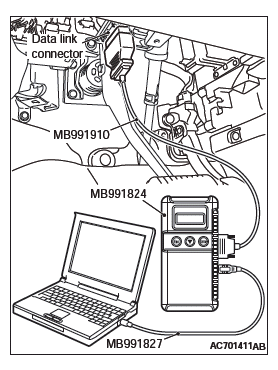
- MB991958 Scan Tool (M.U.T.-III Sub Assembly)
- MB991824: Vehicle Communication Interface (V.C.I.)
- MB991827 M.U.T.-III USB Cable
- MB991910 M.U.T.-III Main Harness A (Vehicles with CAN communication system)
STEP 1. Using scan tool MB991958, diagnose the CAN bus line.
CAUTION To prevent damage to scan tool MB991958, always turn the ignition switch to the "LOCK" (OFF) position before connecting or disconnecting scan tool MB991958.
- Connect scan tool MB991958. Refer to "How to connect the scan tool".
- Turn the ignition switch to the "ON" position.
- Diagnose the CAN bus line.
- Turn the ignition switch to the "LOCK" (OFF) position.
Q: Is the CAN bus line found to be normal?
YES : Go to Step 2.
NO : Repair the CAN bus line.
STEP 2. Recheck for diagnostic trouble code.
Check again if the DTC is set.
- Erase the DTC.
- Turn the ignition switch to the "ON" position.
- Check if the DTC is set.
- Turn the ignition switch to the "LOCK" (OFF) position.
Q: Is the DTC set?
YES : Perform the zero calibration, and check the DTC again. If the DTC is set, replace the front seat cushion frame (RH).
NO : There is an intermittent malfunction such as poor engaged connector(s) or open circuit (Refer to GROUP 00, How to Cope with Intermittent Malfunction).
DTC B1CB2: Occupant Classification-ECU Parameter Table Incompatible
DTC B2212: Occupant Classification-ECU Internal Failure
DTC B2250: Occupant Classification-ECU not Parameter Flash Required
DTC B2262: Occupant Classification-ECU Electrostatic Discharge Event Detected
CAUTION If DTC B1CB2, B2212, B2250, B2262 is set in the occupant classification-ECU, always diagnose the CAN main bus lines.
TROUBLE JUDGMENT
The above DTC is set if an abnormality is detected in the circuit inside the occupant classification-ECU.
TROUBLESHOOTING HINTS
Malfunction of the occupant classification-ECU
DIAGNOSIS
Required Special Tools:
- MB991958: Scan Tool (M.U.T.-III Sub Assembly)
- MB991824: Vehicles Communication Interface (V.C.I.)
- MB991827: M.U.T.-III USB Cable
- MB991910: M.U.T.-III Main Harness A (Vehicles with CAN communication system)
STEP 1. Using scan tool MB991958, diagnose the CAN bus line.
CAUTION To prevent damage to scan tool MB991958, always turn the ignition switch to the "LOCK" (OFF) position before connecting or disconnecting scan tool MB991958.
- Connect scan tool MB991958. Refer to "How to connect the scan tool".
- Turn the ignition switch to the "ON" position.
- Diagnose the CAN bus line.
- Turn the ignition switch to the "LOCK" (OFF) position.
Q: Is the CAN bus line found to be normal?
YES : Go to Step 2.
NO : Repair the CAN bus line.
STEP 2. Recheck for diagnostic trouble code.
Check again if the DTC is set.
- Erase the DTC.
- Turn the ignition switch from "LOCK" (OFF) position to "ON" position.
- Check if DTC is set.
- Turn the ignition switch to the "LOCK" (OFF) position.
Q: Is the DTC set?
YES : Replace the passenger seat cushion frame assembly.
NO : There is an intermittent malfunction such as poor engaged connector(s) or open circuit (Refer to GROUP 00, How to Cope with Intermittent Malfunction).
DTC B210D: Battery Voltage Low
DTC B210E: Battery Voltage High
Occupant Classification-ECU Power Supply Circuit
CAUTION If DTC B210D, B210E is set in the occupant classification- ECU, always diagnose the CAN main bus lines.
TROUBLE JUDGMENT
The occupant classification-ECU sets DTC B210D if the power supply fuse voltage decreases to the specified value or less, and sets DTC B210E if the power supply fuse voltage increases to the specified value or more.
TECHNICAL DESCRIPTION (COMMENT)
The power supply fuse or the occupant classification- ECU may have a problem.
TROUBLESHOOTING HINTS
- The power supply fuse may be defective.
- The occupant classification-ECU may be defective.
- The battery may be defective.
- The generator may be defective.
- The wiring harness or connectors may have loose, corroded, or damaged terminals, or terminals pushed back in the connector
DIAGNOSIS
Required Special Tools:
- MB991958: Scan Tool (M.U.T.-III Sub Assembly)
- MB991824: Vehicle Communication Interface (V.C.I.)
- MB991827: M.U.T.-III USB Cable
- MB991910: M.U.T.-III Main Harness A (Vehicles with CAN communication system)
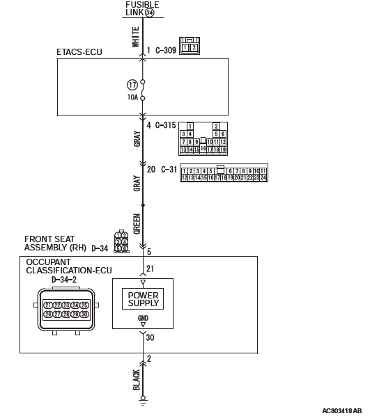
STEP 1. Measure the voltage at the occupant classification-ECU connector.
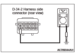
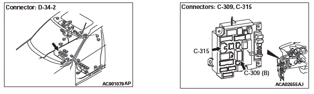
- Disconnect the D-34-2 occupant classification-ECU connector.
- Measure the voltage between the D-34-2 harness side connector terminal No. 21 and the body ground.
- The voltage should measure 12 volts (battery positive voltage).
Q: Is the measured voltage approximately 12 volts (battery positive voltage)?
YES : Go to Step 10.
NO : Go to Step 2.
STEP 2. Power supply fuse No.17 check.
Q: Is the fuse in good condition?
YES : Go to Step 4.
NO : Go to Step 3.
STEP 3. Wiring harness check between the C-315 ETACS-ECU connector terminal No.4 and the D-34-2 occupant classification-ECU connector terminal No. 21.
- Short circuit check for SRS-ECU power supply wire
Q: Is the check result normal?
YES : Replace the power supply fuse.
NO : Repair the wiring harness. And then replace the power supply fuse.
STEP 4. Battery check.
Refer to GROUP 54A, Battery Test.
Q: Is the check result normal?
YES : Go to Step 5.
NO : Charge (B210D only) or replace the battery.
STEP 5. Measure the voltage at the ETACS-ECU connector.
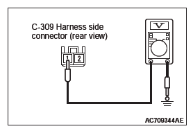
- Disconnect the C-309 ETACS-ECU connector.
- Measure the voltage between the C-309 harness side connector terminal No. 1 and the body ground.
- The voltage should measure 12 volts (battery positive voltage).
Q: Is the measured voltage approximately 12 volts (battery positive voltage)?
YES : Go to Step 7.
NO : Go to Step 6.
STEP 6. Wiring harness check between the fusible link (34) and the C-309 ETACS-ECU connector terminal No. 1.
- Open circuit check for ETACS-ECU power supply wire
Q: Is the check result normal?
YES : Go to Step 10.
NO : Repair the wiring harness.
STEP 7. Using scan tool MB991958, diagnose the ETACS.
CAUTION To prevent damage to scan tool MB991958, always turn the ignition switch to the "LOCK" (OFF) position before connecting or disconnecting scan tool MB991958.
- Connect scan tool MB991958. Refer to "How to connect the scan tool".
- Erase the DTC.
- Turn the ignition switch to the "ON" position.
- Diagnose the CAN bus line.
- Turn the ignition switch to the "LOCK" (OFF) position.
Q: Is the CAN bus line found to be normal?
YES : Diagnose the ETACS.
NO : Check the input signal of ETACS-ECU ignition switch (IG1) (Refer to GROUP 54A − ETACS, Symptom procedures P.54A-789). Than go to step 8.
STEP 8. Using scan tool MB991958, diagnose the CAN bus line.
CAUTION To prevent damage to scan tool MB991958, always turn the ignition switch to the "LOCK" (OFF) position before connecting or disconnecting scan tool MB991958.
- Connect scan tool MB991958. Refer to "How to connect the scan tool".
- Turn the ignition switch to the "ON" position.
- Diagnose the CAN bus line.
- Turn the ignition switch to the "LOCK" (OFF) position.
Q: Is the CAN bus line found to be normal?
YES : Go to Step 9.
NO : Repair the CAN bus line (Refer to GROUP 54C, Diagnosis P.54C-17).
STEP 9. Recheck for diagnostic trouble code.
Check again if the DTC is set.
- Erase the DTC.
- Turn the ignition switch to "ON" position.
- Check if the DTC is set.
- Turn the ignition switch to the "LOCK" (OFF) position.
Q: Is the DTC set?
YES : Go to Step 10.
NO : There is an intermittent malfunction such as poor engaged connector(s) or open circuit (Refer to GROUP 00, How to Cope with Intermittent Malfunction).
STEP 10. Recheck for diagnostic trouble code.
Check again if the DTC is set.
- Erase the DTC.
- Turn the ignition switch to the "ON" position.
- Check if the DTC is set.
- Turn the ignition switch to the "LOCK" (OFF) position.
Q: Is DTC B210D or B210E set?
YES : Replace the passenger seat cushion frame assembly (Refer to GROUP 52A, Front Seat Assembly P.52A-19).
NO : There is an intermittent malfunction such as poor engaged connector(s) or open circuit (Refer to GROUP 00, How to Cope with Intermittent Malfunction).
DTC B2206: Chassis number does not match
CAUTION If DTC B2206 is set in the occupant classification- ECU, always diagnose the CAN bus line.
TROUBLE JUDGMENT
If the registered chassis number is different from the chassis number transmitted on the CAN bus lines, the occupant classification-ECU sets the DTC B2206.
JUDGMENT CRITERIA
If the chassis number registered to occupant classification- ECU and the chassis number on CAN bus lines do not match, the occupant classification-ECU determines that a problem has occurred.
TROUBLESHOOTING HINTS
- Chassis number not written
- The occupant classification-ECU may be defective.
- The CAN bus line may be defective.
DIAGNOSIS
Required Special Tools:
- MB991958: Scan Tool (M.U.T.-III Sub Assembly)
- MB991824: Vehicle Communication Interface (V.C.I.)
- MB991827: M.U.T.-III USB Cable
- MB991910: M.U.T.-III Main Harness A (Vehicles with CAN communication system)
STEP 1. Using scan tool MB991958, diagnose the CAN bus line.
CAUTION To prevent damage to scan tool MB991958, always turn the ignition switch to the "LOCK" (OFF) position before connecting or disconnecting scan tool MB991958.
- Connect scan tool MB991958. Refer to "How to connect the Scan Tool (M.U.T.-III)".
- Turn the ignition switch to the "ON" position.
- Diagnose the CAN bus line.
- Turn the ignition switch to the "LOCK" (OFF) position.
Q: Is the CAN bus line found to be normal?
YES : Accuracy check is performed. Then go to Step 2.
NO : Repair the CAN bus line.
STEP 2. Recheck for diagnostic trouble code.
Check again if the DTC is set to the occupant classification- ECU.
- Zero calibration of occupant classification-ECU.
- Erase the DTC.
- Turn the ignition switch from "LOCK" (OFF) position to "ON" position.
- Check if DTC is set.
- Turn the ignition switch to the "LOCK" (OFF) position.
Q: Is the DTC set?
YES : Replace the passenger seat cushion frame assembly (Refer to GROUP 52A, Front Seat Assembly).
NO : There is an intermittent malfunction such as poor engaged connector(s) or open circuit (Refer to GROUP 00, How to Cope with Intermittent Malfunction).
READ NEXT:
 DTC U0020, U0021, U0022, U0023, U0024, U0025, U0026, U0141, U0151, U0155, U0164,
U0168, U0184, U0195, U0245, U1419, U141A, U141B, U141C, U1423
DTC U0020, U0021, U0022, U0023, U0024, U0025, U0026, U0141, U0151, U0155, U0164,
U0168, U0184, U0195, U0245, U1419, U141A, U141B, U141C, U1423
DTC U0020: CAN-B Bus Off Performance
DTC U0021: CAN-B Bus(H1) Circuit Open
DTC U0022: CAN-B Bus(H1) Shorted to Circuit Ground
DTC U0023: CAN-B Bus(H1) Shorted to Circuit Power Supply
DTC U0024: CAN-B
Post-collision Diagnosis
To inspect and service the SRS after a collision (whether or not
the air bags have deployed), perform the following steps.
SRS-ECU MEMORY CHECK
Required Special Tool:
MB991958: Scan Tool (M.U.T.-III
Air Bag Module(s) and Clock Spring
REMOVAL AND INSTALLATION
WARNING
Never attempt to disassemble or repair the air bag modules or
clock spring. If faulty,
replace it.
Do not drop the air bag modules or clock spring or allow conta
SEE MORE:
DTC U1415, U0019, U0141, U0151, U0154, U0155, U0168, U0184, U0195
DTC U1415:Coding Not Completed
CAUTION
If DTC U1415 is set in the A/C-ECU, diagnose the
CAN main bus line.
CAUTION
Whenever the ECU is replaced, ensure that the
communication circuit is normal.
TROUBLE JUDGMENT
The A/C-ECU receives the vehicle information signals
from the ETACS-ECU via the CAN bus
Information screen display
Brake warning display
When “RELEASE PARKING BRAKE” is displayed This warning is displayed if you drive
with the parking brake still applied. The warning lamp in the instrument cluster
only illuminates when the parking brake is applied.
CAUTION:
● If a vehicle is driven without rel
