Mitsubishi Outlander: Engine Control
GENERAL INFORMATION
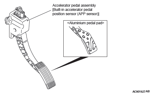
For the accelerator system, the electronic throttle valve control system, disposing of the accelerator cable, is adopted.
This system determines the amount of pressure applied to the accelerator pedal using the built-in accelerator pedal position sensor of the accelerator pedal assembly to control the throttle valve angle electrically.
- A resin arm is employed to reduce weight.
- The aluminum pedal pad has been adopted to enhance the sporty image <some models>.
CONSTRUCTION DIAGRAM
ENGINE CONTROL SYSTEM DIAGNOSIS
INTRODUCTION
If there is a malfunction in the engine control system, the accelerator pedal or throttle body may be faulty.
TROUBLESHOOTING STRATEGY
Use these steps to plan your diagnostic strategy.
If you follow them carefully, you will be sure that you have exhausted most of the possible ways to find an engine control system fault.
1. Gather information from the customer.
2. Verify that the condition described by the customer exists.
3. Find the malfunction by following the Symptom Chart.
4. Verify that the malfunction is eliminated.
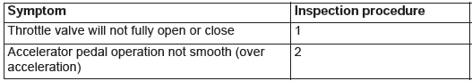
SYMPTOM CHART
SYMPTOM PROCEDURES
Inspection Procedure 1: Throttle Valve will not Fully Open or Close
COMMENT
The throttle body or accelerator pedal position sensor (APP sensor) is suspected.
TROUBLESHOOTING HINTS (The most likely causes for this case:)
- Malfunction of the throttle body.
- Malfunction of the APP sensor.
- Malfunction of the engine control module (ECM).
DIAGNOSIS
Required Special Tools:
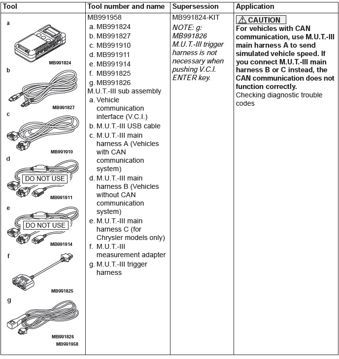
- MB991958: Scan Tool (M.U.T.-III Sub Assembly)
- MB991824: Vehicle Communication Interface (V.C.I.)
- MB991827: M.U.T.-III USB Cable
- MB991910: M.U.T.-III Main Harness A
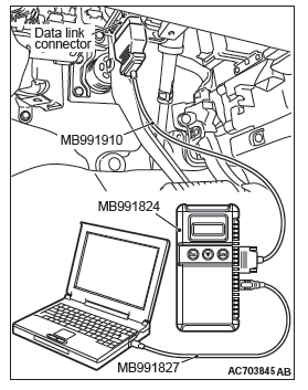
STEP 1. Using scan tool MB991958, read the MFI system diagnostic trouble code.
CAUTION
To prevent damage to scan tool MB991958, always turn the ignition switch to the "LOCK" (OFF) position before connecting or disconnecting scan tool MB991958.
- Ensure that the ignition switch is at the "LOCK" (OFF) position.
- Start up the personal computer.
- Connect special tool MB991827 to special tool MB991824 and the personal computer.
- Connect special tool MB991910 to special tool MB991824.
- Connect special tool MB991910 to the data link connector.
- Turn the power switch of special tool MB991824 to the "ON" position.
NOTE: When special tool MB991824 is energized, special tool MB991824 indicator light will be illuminated in a green color.
- Start the M.U.T.-III system on the personal computer.
- Turn the ignition switch to the "ON" position.
- Check for MFI system diagnostic trouble code (Refer to GROUP 13A, Diagnostic Function − How to Read and Erase Diagnostic Trouble Codes) <2.4L Engine> or (Refer to GROUP 13B, Diagnostic Function − How to Read and Erase Diagnostic Trouble Codes) <3.0L Engine>.
- Turn the ignition switch to the "LOCK" (OFF) position, and then remove scan tool MB991958 in the reverse order of installation.

Q: Is any DTC set?
YES : Repair MFI system.
NO : Go to Step 2.
STEP 2. Retest the system.
Q: Does the throttle valve fully open and close?
YES : The procedure is complete.
NO : Return to Step 1.
Inspection Procedure 2: Accelerator Pedal Operation not Smooth (Over Acceleration)
COMMENT
The accelerator pedal, its installation condition or the APP sensor is suspected.
TROUBLESHOOTING HINTS (The most likely causes for this case:)
- Malfunction of the accelerator pedal.
- Incorrectly installed accelerator pedal.
- Malfunction of the APP sensor.
DIAGNOSIS
Required Special Tools:
- MB991958: Scan Tool (M.U.T.-III Sub Assembly)
- MB991824: V.C.I.
- MB991827: M.U.T.-III USB Cable
- MB991910: M.U.T.-III Main Harness A
STEP 1. Check if the accelerator pedal is installed correctly.
Q: Is the accelerator pedal installed correctly?
YES : Go to Step 2.
NO : Remove and reinstall the accelerator pedal. Then go to Step 3.
STEP 2. Using scan tool MB991958, read the MFI system diagnostic trouble code.
CAUTION
To prevent damage to scan tool MB991958, always turn the ignition switch to the "LOCK" (OFF) position before connecting or disconnecting scan tool MB991958.
- Ensure that the ignition switch is at the "LOCK" (OFF) position.
- Start up the personal computer.
- Connect special tool MB991827 to special tool MB991824 and the personal computer.
- Connect special tool MB991910 to special tool MB991824.
- Connect special tool MB991910 to the data link connector.
- Turn the power switch of special tool MB991824 to the "ON" position.
NOTE: When special tool MB991824 is energized, special tool MB991824 indicator light will be illuminated in a green color.
- Start the M.U.T.-III system on the personal computer.
- Turn the ignition switch to the "ON" position.
- Check for MFI system diagnostic trouble code (Refer to GROUP 13A, Diagnostic Function − How to Read and Erase Diagnostic Trouble Codes) <2.4L Engine> or (Refer to GROUP 13B, Diagnostic Function − How to Read and Erase Diagnostic Trouble Codes) <3.0L Engine>.
- Turn the ignition switch to the "LOCK" (OFF) position, and then remove scan tool MB991958 in the reverse order of installation.
Q: Is any DTC set?
YES : Repair MFI system. Then go to Step 3.
NO : Go to Step 3.
STEP 3. Retest the system.
Q: Does the accelerator pedal work normally?
YES : The procedure is complete.
NO : Return to Step 1.
SPECIAL TOOL
ACCELERATOR PEDAL
REMOVAL AND INSTALLATION
Pre-removal and Post-installation Operation
- Bottom Cover Assembly (driver's seat) Removal and Installation.
<Vehicles without aluminum pedal pad>
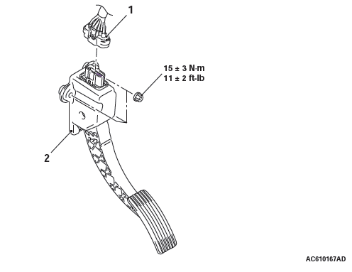
Removal steps
- Accelerator pedal position sensor connector
- Accelerator pedal assembly
<Vehicles with aluminum pedal pad>
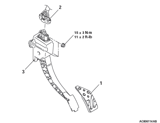
Removal steps
- Accelerator pedal pad
- Accelerator pedal position sensor connector
- Accelerator pedal assembly
READ NEXT:
 General Information
By using the cruise control system, the driver can
drive at preferred speeds in a range of approximately
40 to 160 km/h (25 to 100 mph) without depressing
the accelerator pedal.
For this cruise contr
Diagnostic Trouble Code Procedures
DTC 15: Cruise Control Switch System
Cruise Control Switch Circuit
CIRCUIT OPERATION
This circuit judges the signals of each switch
("ON/OFF", "CANCEL", "COAST/SET" and
"ACC/RES") of the cruise cont
SEE MORE:
Automatic Transaxle Diagnosis (A/T)
DIAGNOSTIC TROUBLESHOOTING FLOW
INTRODUCTION TO A/T DIAGNOSIS
When the A/T is failed, have an interview with the
user to gather precise information on the failure status.
After that, perform on-board test to check if the
failure is reproduced, and then start repair work. If
the repair work is sta
KOS-ECU, Keyless Operation Key, TPMS Transmitter
KOS-ECU
REMOVAL AND INSTALLATION
CAUTION
If KOS-ECU is replaced, refer to ID code registration
need judgment table P.42B to complete
the registration of each ID code.
Removal
KOS-ECU
Exterior Transmitter Antenna
Assembly, Interior Transmitter
Antenna Assembly, Receiver
Antenna Module
REMOVAL AN
