Mitsubishi Outlander: Diagnostic Trouble Code Procedures
DTC 15: Cruise Control Switch System
Cruise Control Switch Circuit
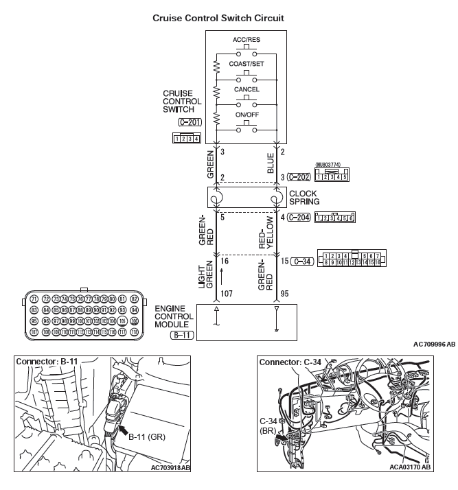
CIRCUIT OPERATION
This circuit judges the signals of each switch ("ON/OFF", "CANCEL", "COAST/SET" and "ACC/RES") of the cruise control switch. The ECM detects the state of the cruise control switch by sensing the voltages shown below.
- When all switches are released: 4.7 − 5.0 volts
- When the "ON/OFF" switch is pressed: 0 − 0.5 volt
- When the "CANCEL" switch is pressed: 1.0 − 1.8 volts
- When the "COAST/SET" switch is pressed: 2.3 − 3.0 volts
- When the "ACC/RES" switch is pressed: 3.5 − 4.2 volts
DTC SET CONDITIONS
Check Condition
- The "CRUISE" indicator light illuminates.
Judgment Criteria
- This DTC is set when the ECM terminal voltage is different from the standard value.
- Or, this DTC is set when the "COAST/SET" switch or "ACC/RES" switch is stuck to ON.
ROUBLESHOOTING HINTS (THE MOST LIKELY CAUSES FOR THIS CASE:)
- Damaged harness or connector.
- Malfunction of the cruise control switch.
- Malfunction of the clock spring.
- Malfunction of the ECM.
DIAGNOSTIC PROCEDURE
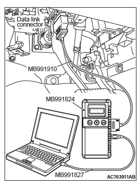
Required Special Tools:
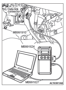
- MB991958: Scan Tool (M.U.T.-III Sub Assembly)
- MB991824: V.C.I.
- MB991827: M.U.T.-III USB Cable
- MB991910: M.U.T.-III Main Harness A
- MB991223: Harness Set
- MB992006: Extra Fine Probe
- MB992110: Power Plant ECU Check Harness
STEP 1. Using scan tool MB991958, check the data list item 86: Main switch, item 92: Set switch, item 91: Resume switch and item 75: Cancel switch.
CAUTION
To prevent damage to scan tool MB991958, always turn the ignition switch to the "LOCK" (OFF) position before connecting or disconnecting scan tool MB991958.
- Connect scan tool MB991958 to the data link connector
- Turn the ignition switch to the "ON" position.
- Set scan tool MB991958 to data reading mode for cruise control system
- Item 75: Cancel switch.
- When "CANCEL" switch is pressed, the display on scan tool MB991958 should be "ON".
- When "CANCEL" switch is released, the display on scan tool MB991958 should be "OFF".
- Item 86: Main switch.
- When "ON/OFF" switch is pressed, the display on scan tool MB991958 should be "ON".
- When "ON/OFF" switch is pressed again, the display on scan tool MB991958 should be "OFF".
- Item 91: Resume switch.
- When "ACC/RES" switch is pressed, the display on scan tool MB991958 should be "ON".
- When "ACC/RES" switch is released, the display on scan tool MB991958 should be "OFF".
- Item 92: Set switch.
- When "COAST/SET" switch is pressed, the display on scan tool MB991958 should be "ON".
- When "COAST/SET" switch is released, the display on scan tool MB991958 should be "OFF".
Q: Is the switch operating properly?
YES : Go to Step 25.
NO : Go to Step 2.
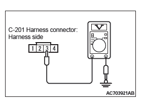
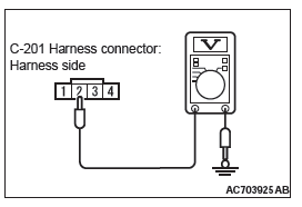
STEP 2. Measure the power supply voltage at cruise control switch connector C-201 by backprobing.
- Remove the cruise control switch from the steering wheel with the cruise control switch connector connected.
- Connect the negative (−) battery terminal that was disconnected when the driver's air bag module was removed.
- Do not disconnect cruise control switch connector C-201.
- Turn the ignition switch to the "ON" position.
- Do not operate the cruise control switch.
- Measure the power supply voltage between cruise control switch connector C-201 terminal number 3 and body ground by backprobing.
Q: Is the measured voltage between 4.7 and 5.0 volts?
YES : Go to Step 14.
NO : Go to Step 3.
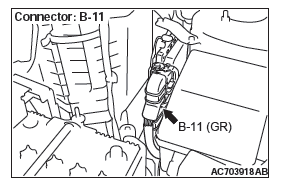
STEP 3. Measure the power supply voltage at ECM connector B-11.
- Disconnect all the connectors from the ECM [Refer to GROUP 13A, Engine Control Module (ECM) ] <2.4L Engine> or [Refer to GROUP 13B, Engine Control Module (ECM) ] <3.0L Engine>.
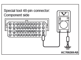
- Connect special tool MB992110 between the ECM and the body-side harness connector.
- Turn the ignition switch to the "ON" position.
- Do not operate the cruise control switch.
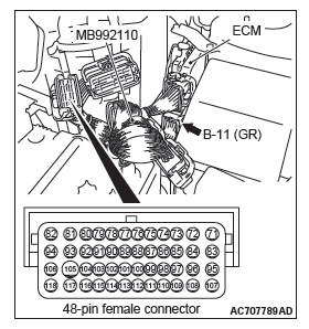
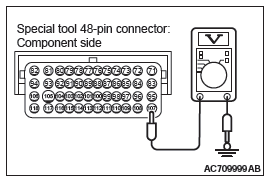
- Measure the power supply voltage between special tool 48-pin connector terminal number 107 (ECM connector B-11 terminal number 107) and body ground.
Q: Is the measured voltage between 4.7 and 5.0 volts?
YES : Go to Step 10.
NO : Go to Step 4.
STEP 4. Check ECM connector B-11 for loose, corroded or damaged terminals, or terminals pushed back in the connector.
Q: Are the connector and terminals in good condition?
YES : Go to Step 5.
NO : Repair or replace the damaged connector. Then go to Step 26.
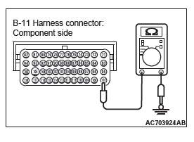
STEP 5. Check the harness wire for short circuit to body ground between the ECM connector B-11 terminal number 107 and the cruise control switch connector C-201 terminal number 3.
- Disconnect ECM connector B-11 and measure at the harness connector side [Refer to GROUP 13A, Engine Control Module (ECM) ] <2.4L Engine> or [Refer to GROUP 13B, Engine Control Module (ECM) ] <3.0L Engine>.
- Turn the ignition switch to the "LOCK" (OFF) position.
- Measure the continuity between ECM connector B-11 terminal number 107 and body ground.
Q: Is the measured continuity open circuit?
YES : Go to Step 24.
NO : Go to Step 6.
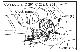
STEP 6. Check intermediate connector C-34, cruise control switch connector C-201 ,and clock spring connectors C-202 and C-204, for loose, corroded or damaged terminals, or terminals pushed back in the connector.
Q: Are the connectors and terminals in good condition?
YES : Go to Step 7.
NO : Repair or replace the damaged connector. Then go to Step 26.
STEP 7. Check the harness wire between ECM connector B-11 terminal number 107 and clock spring connector C-204 terminal number 5, and between clock spring connector C-202 terminal number 2 and cruise control switch connector C-201 terminal number 3, for damage.
Check harness wire for short circuit and damage.
Q: Are the harness wires in good condition?
YES : Go to Step 8.
NO : Repair or replace the damaged harness wire. Then go to Step 26.
STEP 8. Check the clock spring.
Q: Is the clock spring in good condition?
YES : Go to Step 9.
NO : Replace the clock spring. Then go to Step 26.
STEP 9. Check the cruise control switch.
Q: Is the cruise control switch operating properly?
YES : Go to Step 13.
NO : Replace the cruise control switch. Then go to Step 26.
STEP 10. Check ECM connector B-11, intermediate connector C-34, cruise control switch connector C-201, and clock spring connectors C-202 and C-204, for loose, corroded or damaged terminals, or terminals pushed back in the connector.
Q: Are the connectors and terminals in good condition?
YES : Go to Step 11.
NO : Repair or replace the damaged connector. Then go to Step 26.
STEP 11. Check the harness wire between ECM connector B-11 terminal number 107 and clock spring connector C-204 terminal number 5, and between clock spring connector C-202 terminal number 2 and cruise control switch connector C-201 terminal number 3, for damage.
Check harness wire for open circuit and damage.
Q: Are the harness wires in good condition?
YES : Go to Step 12.
NO : Repair or replace the damaged harness wire. Then go to Step 26.
STEP 12. Check the clock spring.
Q: Is the clock spring in good condition?
YES : Go to Step 13.
NO : Replace the clock spring. Then go to Step 26.
STEP 13. Using scan tool MB991958, check data list item 75: Cancel switch, item 86: Main switch, item 91: Resume switch and item 92: Set switch.
- Connect scan tool MB991958 to the data link connector.
- Turn the ignition switch to the "ON" position.
- Set scan tool MB991958 to data reading mode for cruise control system.
- Item 75: Cancel switch.
- When "CANCEL" switch is pressed, the display on scan tool MB991958 should be "ON".
- When "CANCEL" switch is released, the display on scan tool MB991958 should be "OFF".
- Item 86: Main switch.
- When "ON/OFF" switch is pressed, the display on scan tool MB991958 should be "ON".
- When "ON/OFF" switch is pressed again, the display on scan tool MB991958 should be "OFF".
- Item 91: Resume switch.
- When "ACC/RES" switch is pressed, the display on scan tool MB991958 should be "ON".
- When "ACC/RES" switch is released, the display on scan tool MB991958 should be "OFF".
- Item 92: Set switch.
- When "COAST/SET" switch is pressed, the display on scan tool MB991958 should be "ON".
- When "COAST/SET" switch is released, the display on scan tool MB991958 should be "OFF".
Q: Is the switch operating properly?
YES : Go to Step 25.
NO : Go to Step 14.
STEP 14. Measure the ground voltage at cruise control switch connector C-201 by backprobing.
- Remove the cruise control switch from the steering wheel with the cruise control switch connector connected.
- Connect the negative (−) battery terminal that was disconnected when the driver's air bag module was removed.
- Do not disconnect cruise control switch connector C-201.
- Turn the ignition switch to the "ON" position.
- Press and hold the "ON/OFF" switch, and measure the ground voltage between cruise control switch connector C-201 terminal number 2 and body ground by backprobing.
Q: Is the measured voltage 0.5 volt or less?
YES : Go to Step 20.
NO : Go to Step 15.
STEP 15. Measure the ground voltage at ECM connector B-11.
- Disconnect all the connectors from the ECM [Refer to GROUP 13A, Engine Control Module (ECM) ] <2.4L Engine> or [Refer to GROUP 13B, Engine Control Module (ECM) ] <3.0L Engine>.
- Connect special tool MB992110 between the ECM and the body-side harness connector.
- Turn the ignition switch to the "ON" position.
- Press and hold the "ON/OFF" switch, and measure the ground voltage between special tool 48-pin connector terminal number 95 (ECM connector B-11 terminal number 95) and body ground.
Q: Is the measured voltage 0.5 volt or less?
YES : Go to Step 17.
NO : Go to Step 16.
STEP 16. Check ECM connector B-11 for loose, corroded or damaged terminals, or terminals pushed back in the connector.
Q: Are the connector and terminals in good condition?
YES : Go to Step 24.
NO : Repair or replace the damaged connector. Then go to Step 26.
STEP 17. Check intermediate connector C-34, cruise control switch connector C-201, and clock spring connectors C-202 and C-204, for loose, corroded or damaged terminals, or terminals pushed back in the connector.
Q: Are the connectors and terminals in good condition?
YES : Go to Step 18.
NO : Repair or replace the damaged connector. Then go to Step 26.
STEP 18. Check the harness wire between cruise control switch connector C-201 terminal number 2 and clock spring connector C-202 terminal number 3, and between clock spring connector C-204 terminal number 4 and ECM connector B-11 terminal number 95, for damage.
Check harness wire for open circuit and damage.
Q: Are the harness wires in good condition?
YES : Go to Step 19.
NO : Repair or replace the damaged harness wire. Then go to Step 26.
STEP 19. Check the clock spring.
Q: Is the clock spring in good condition?
YES : Go to Step 24.
NO : Replace the clock spring. Then go to Step 26.
STEP 20. Check ECM connector B-11, intermediate connector C-34, cruise control switch connector C-201, and clock spring connectors C-202 and C-204, for loose, corroded or damaged terminals, or terminals pushed back in the connector.
Q: Are the connectors and terminals in good condition?
YES : Go to Step 21.
NO : Repair or replace the damaged connector. Then go to Step 26.
STEP 21. Check the harness wire between cruise control switch connector C-201 terminal number 2 and clock spring connector C-202 terminal number 3, and between clock spring connector C-204 terminal number 4 and ECM connector B-11 terminal number 95, for damage.
Check harness wire for short circuit and damage.
Q: Are the harness wires in good condition?
YES : Go to Step 22.
NO : Repair or replace the damaged harness wire. Then go to Step 26.
STEP 23. Check the cruise control switch.
Q: Is the cruise control switch operating properly?
YES : Go to Step 24.
NO : Replace the cruise control switch.
Then go to Step 26.
STEP 24. Using scan tool MB991958, check data list item 75: Cancel switch, item 86: Main switch, item 91: Resume switch and item 92: Set switch.
- Connect scan tool MB991958 to the data link connector.
- Turn the ignition switch to the "ON" position.
- Set scan tool MB991958 to data reading mode for cruise control system.
- Item 75: Cancel switch.
- When "CANCEL" switch is pressed, the display on scan tool MB991958 should be "ON".
- When "CANCEL" switch is released, the display on scan tool MB991958 should be "OFF".
- Item 86: Main switch.
- When "ON/OFF" switch is pressed, the display on scan tool MB991958 should be "ON".
- When "ON/OFF" switch is pressed again, the display on scan tool MB991958 should be "OFF".
- Item 91: Resume switch.
- When "ACC/RES" switch is pressed, the display on scan tool MB991958 should be "ON".
- When "ACC/RES" switch is released, the display on scan tool MB991958 should be "OFF".
- Item 92: Set switch.
- When "COAST/SET" switch is pressed, the display on scan tool MB991958 should be "ON".
- When "COAST/SET" switch is released, the display on scan tool MB991958 should be "OFF".
Q: Is the switch operating properly?
YES : Go to Step 25.
NO : Replace the ECM [Refer to GROUP 13A, Engine Control Module (ECM) ] <2.4L Engine> or [Refer to GROUP 13B, Engine Control Module (ECM] <3.0L Engine>. Then go to Step 26.
STEP 25. Read the cruise control system DTC.
- Disconnect the negative (−) battery terminal, to erase the DTC of the cruise control system.
- Connect the negative (−) battery terminal.
- Turn the ignition switch to the "ON" position, and press the "ON/OFF" switch to turn the cruise control system to ON (turn on the "CRUISE" indicator light.)
- After turning the cruise control system to ON, when 2 minutes or more has elapsed without operating the cruise control switches, read the DTC of the cruise control system.
Q: Is DTC 15 set?
YES : Replace the ECM [Refer to GROUP 13A, Engine Control Module (ECM) ] <2.4L Engine> or [Refer to GROUP 13B, Engine Control Module (ECM) ] <3.0L Engine>. Then go to Step 26.
NO : It can be assumed that this malfunction is intermittent (Refer to GROUP 00, How to Use Troubleshooting/Inspection Service Points − How to Cope with Intermittent Malfunction)
STEP 26. Using scan tool MB991958, check data list item 75: Cancel switch, item 86: Main switch, item 91: Resume switch and item 92: Set switch.
- Connect scan tool MB991958 to the data link connector.
- Turn the ignition switch to the "ON" position.
- Set scan tool MB991958 to data reading mode for cruise control system.
- Item 75: Cancel switch.
- When "CANCEL" switch is pressed, the display on scan tool MB991958 should be "ON".
- When "CANCEL" switch is released, the display on scan tool MB991958 should be "OFF".
- Item 86: Main switch.
- When "ON/OFF" switch is pressed, the display on scan tool MB991958 should be "ON".
- When "ON/OFF" switch is pressed again, the display on scan tool MB991958 should be "OFF".
- Item 91: Resume switch.
- When "ACC/RES" switch is pressed, the display on scan tool MB991958 should be "ON".
- When "ACC/RES" switch is released, the display on scan tool MB991958 should be "OFF".
- Item 92: Set switch.
- When "COAST/SET" switch is pressed, the display on scan tool MB991958 should be "ON".
- When "COAST/SET" switch is released, the display on scan tool MB991958 should be "OFF".
Q: Is the switch operating properly?
YES : Go to Step 27.
NO : Return to Step 2.
STEP 27. Read the cruise control system DTC.
- Disconnect the negative (−) battery terminal, to erase the DTC of the cruise control system.
- Connect the negative (−) battery terminal.
- Turn the ignition switch to the "ON" position, and press the "ON/OFF" switch to turn the cruise control system to ON (turn on the "CRUISE" indicator light.)
- After turning the cruise control system to ON, when 2 minutes or more has elapsed without operating the cruise control switches, read the DTC of the cruise control system.
Q: Is DTC 15 set?
YES : Return to Step 1.
NO : The procedure is complete.
DTC 22: Stoplight Switch System
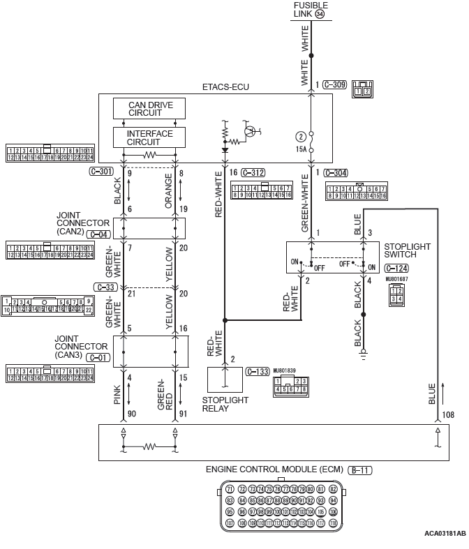
Stoplight Switch System Circuit
CIRCUIT OPERATION
- For the stoplight switch, two switches, a stoplight switch for the stoplight illumination and a brake switch exclusively for the cruise control system, are incorporated to improve the reliability.
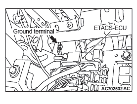
- As for the stoplight switch, when the brake pedal is depressed/released, the stoplight switch ON/OFF signal is transmitted from the ETACS-ECU to the ECM via CAN bus line.
- As for the brake switch, the ECM connector B-11 terminal number 108 monitor the state of the brake switch. The brake switch turn ON/OFF when the brake pedal is depressed/released, and the input signal to the ECM connector B-11 terminal number 108 changes. According to this change, the ECM judges the state of the brake switch.
DTC SET CONDITIONS
Check Condition
- The "CRUISE" indicator light illuminates.
Judgment Criteria
- Open/short in stoplight switch circuit.
- Open circuit in the brake switch circuit (between ECM connector B-11 terminal number 108 and body ground.)
- Malfunction of CAN bus line.
TROUBLESHOOTING HINTS (THE MOST LIKELY CAUSES FOR THIS CASE:)
- Malfunction of CAN bus system.
- Damaged harness or connector.
- Malfunction of the fuse No.2 at the ETACS-ECU.
- Malfunction of the stoplight switch.
- Malfunction of the stoplight relay.
- Malfunction of the ETACS-ECU.
- Malfunction of the ECM.
DIAGNOSTIC PROCEDURE
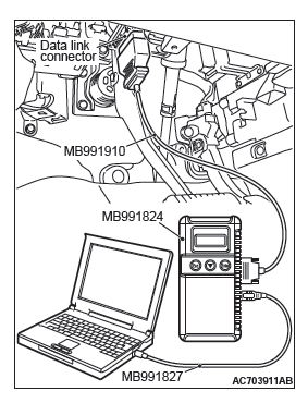
Required Special Tools:
- MB991958: Scan Tool (M.U.T.-III Sub Assembly)
- MB991824: V.C.I.
- MB991827: M.U.T.-III USB Cable
- MB991910: M.U.T.-III Main Harness A
- MB991223: Harness Set
- MB992006: Extra Fine Probe
CAUTION
If there is any problem in the CAN bus lines, an incorrect DTC may be set. Prior to this diagnosis, diagnose the CAN bus lines.
STEP 1. Using scan tool MB991958, diagnose the CAN bus line.
CAUTION
To prevent damage to scan tool MB991958, always turn the ignition switch to the "LOCK" (OFF) position before connecting or disconnecting scan tool MB991958.
- Connect scan tool MB991958 to the data link connector.
- Turn the ignition switch to the "ON" position.
- Set scan tool MB991958 to diagnose the CAN bus line.
Q: Is the check result satisfactory?
YES : Go to Step 2.
NO : Repair the CAN bus lines.
Then go to Step 12.
STEP 2. Using scan tool MB991958, check the data list item 74: Brake light switch.
- Connect scan tool MB991958 to the data link connector.
- Turn the ignition switch to the "ON" position.
- Set scan tool MB991958 to data reading mode for cruise control system.
- Item 74: Brake light switch.
- When the brake pedal is depressed, the display on scan tool MB991958 should be "ON".
- When the brake pedal is released, the display on scan tool MB991958 should be "OFF".
Q: Is the switch operating properly?
YES : Go to Step 6.
NO : Go to Step 3.
STEP 3. Check the stoplight operation.
Check the stoplight operation.
OK:
Brake pedal depressed: Stoplight will illuminate
Brake pedal not depressed: Stoplight does not illuminate
Q: Is the stoplight operating properly?
YES : Go to Step 4.
NO : Check the stoplight system. Then go to Step 12.
STEP 4. Using scan tool MB991958, check the ETACS system data list item 290: Brake light switch.
- Connect scan tool MB991958 to the data link connector.
- Turn the ignition switch to the "ON" position.
- Set scan tool MB991958 to data reading mode for ETACS system.
- Item 290: Brake light switch.
- When the brake pedal is depressed, the display on scan tool MB991958 should be "ON".
- When the brake pedal is released, the display on scan tool MB991958 should be "OFF".
Q: Is the switch operating properly?
YES : Go to Step 5.
NO : Replace the ETACS-ECU. Then go to Step 12.
STEP 5. Using scan tool MB991958, check the data list item 74: Brake light switch.
- Connect scan tool MB991958 to the data link connector.
- Turn the ignition switch to the "ON" position.
- Set scan tool MB991958 to data reading mode for cruise control system.
- Item 74: Brake light switch.
- When the brake pedal is depressed, the display on scan tool MB991958 should be "ON".
- When the brake pedal is released, the display on scan tool MB991958 should be "OFF".
Q: Is the switch operating properly?
YES : Go to Step 6.
YES : Replace the ECM [Refer to GROUP 13A, Engine Control Module (ECM) ] <2.4L Engine> or [Refer to GROUP 13B, Engine Control Module (ECM) ] <3.0L Engine>. Then go to Step 12.
STEP 6. Using scan tool MB991958, check the data list item 89: Normally closed brake switch.
- Connect scan tool MB991958 to the data link connector.
- Turn the ignition switch to the "ON" position.
- Set scan tool MB991958 to data reading mode for cruise control system.
- Item 89: Normally closed brake switch.
- When the brake pedal is depressed, the display on scan tool MB991958 should be "ON".
- When the brake pedal is released, the display on scan tool MB991958 should be "OFF".
Q: Is the switch operating properly?
YES : Go to Step 11.
NO : Go to Step 7.
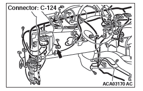
STEP 7. Check ECM connector B-11 and stoplight switch connector C-124 for loose, corroded or damaged terminals, or terminals pushed back in the connector.
Q: Are the connectors and terminals in good condition?
YES : Go to Step 8.
NO : Repair or replace the damaged connector. Then go to Step 12.
STEP 8. Check the harness wire between ECM connector B-11 terminal number 108 and stoplight switch connector C-124 terminal number 3, and between stoplight switch connector C-124 terminal number 4 and body ground, for damage.
Check harness wire for open/short circuit and damage.
Q: Are the harness wires in good condition?
YES : Go to Step 9.
NO : Repair or replace the damaged harness wire. Then go to Step 12.
STEP 9. Check the stoplight switch.
Refer to GROUP 35A, Brake Pedal, Inspection − Stoplight Switch Check.
Q: Is the stoplight switch operating properly?
YES : Go to Step 10.
NO : Replace the stoplight switch. Then go to Step 12.
STEP 10. Using scan tool MB991958, check the data list item 89: Normally closed brake switch.
- Connect scan tool MB991958 to the data link connector.
- Turn the ignition switch to the "ON" position.
- Set scan tool MB991958 to data reading mode for cruise control system.
- Item 89: Normally closed brake switch.
- When the brake pedal is depressed, the display on scan tool MB991958 should be "ON".
- When the brake pedal is released, the display on scan tool MB991958 should be "OFF".
Q: Is the switch operating properly?
YES : Go to Step 11.
NO : Replace the ECM [Refer to GROUP 13A, Engine Control Module (ECM) ] <2.4L Engine> or [Refer to GROUP 13B, Engine Control Module (ECM) ] <3.0L Engine>. Then go to Step 12.
STEP 11. Read the cruise control system DTC.
- Disconnect the negative (−) battery terminal, to erase the DTC of the cruise control system.
- Connect the negative (−) battery terminal.
- Turn the ignition switch to the "ON" position, and press the "ON/OFF" switch to turn the cruise control system to ON (turn on the "CRUISE" indicator light.)
- With the cruise control switches not operated, depress the brake pedal for several seconds, and then read the DTC of the cruise control system.
Q: Is DTC 22 set?
YES : Replace the ECM [Refer to GROUP 13A, Engine Control Module (ECM) ] <2.4L Engine> or [Refer to GROUP 13B, Engine Control Module (ECM) ] <3.0L Engine>. Then go to Step 12.
NO : It can be assumed that this malfunction is intermittent (Refer to GROUP 00, How to Use Troubleshooting/Inspection Service Points − How to Cope with Intermittent Malfunction.)
STEP 12. Using scan tool MB991958, check the data list item 74: Brake light switch, item 89: Normally closed brake switch.
- Connect scan tool MB991958 to the data link connector.
- Turn the ignition switch to the "ON" position.
- Set scan tool MB991958 to data reading mode for cruise control system.
- Item 74: Brake light switch.
- When the brake pedal is depressed, the display on scan tool MB991958 should be "ON".
- When the brake pedal is released, the display on scan tool MB991958 should be "OFF".
- Item 89: Normally closed brake switch.
- When the brake pedal is depressed, the display on scan tool MB991958 should be "ON".
- When the brake pedal is released, the display on scan tool MB991958 should be "OFF".
Q: Is the switch operating properly?
YES : Go to Step 13.
NO : Return to Step 2.
STEP 13. Read the cruise control system DTC.
- Disconnect the negative (−) battery terminal, to erase the DTC of the cruise control system.
- Connect the negative (−) battery terminal.
- Turn the ignition switch to the "ON" position, and press the "ON/OFF" switch to turn the cruise control system to ON (turn on the "CRUISE" indicator light.)
- With the cruise control switches not operated, depress the brake pedal for several seconds, and then read the DTC of the cruise control system.
Q: Is DTC P22 set?
YES : Return to Step 1.
NO : The procedure is complete.
DTC 23: ECM and Its Related Component
DTC SET CONDITIONS
This DTC is set when there is failure in the ECM and its related components.
TROUBLESHOOTING HINTS (THE MOST LIKELY CAUSES FOR THIS CASE:)
- Malfunction of the MFI system.
- Malfunction of the ECM.
DIAGNOSIS
Required Special Tools:
- MB991958: Scan Tool (M.U.T.-III Sub Assembly)
- MB991824: V.C.I.
- MB991827: M.U.T.-III USB Cable
- MB991910: M.U.T.-III Main Harness A
STEP 1. Using scan tool MB991958, read the MFI system diagnostic trouble code.
CAUTION
To prevent damage to scan tool MB991958, always turn the ignition switch to the "LOCK" (OFF) position before connecting or disconnecting scan tool MB991958.
- Connect scan tool MB991958 to the data link connector.
- Turn the ignition switch to the "ON" position.
- Check for MFI system diagnostic trouble code (Refer to GROUP 13A, Diagnostic Function − How to Read and Erase Diagnostic Trouble Codes) <2.4L Engine> or (Refer to GROUP 13B, Diagnostic Function − How to Read and Erase Diagnostic Trouble Codes) <3.0L Engine>.
- Turn the ignition switch to the "LOCK" (OFF) position.
- Disconnect scan tool MB991958.
Q: Is any DTC set?
YES : Diagnose the MFI system (Refer to GROUP 13A, Diagnostic Trouble Code Chart) <2.4L Engine> or (Refer to GROUP 13B, Diagnostic Trouble Code Chart) <3.0L Engine>. Then go to Step 3.
NO : Go to Step 2.
STEP 2. Read the cruise control system diagnostic trouble code.
- Erase diagnostic trouble code.
- Turn the ignition switch to the "ON" position, and press the "ON/OFF" switch to turn the cruise control system to ON (turn on the "CRUISE" indicator light).
- After turning the cruise control system to ON, when 2 minutes or more has elapsed without operating the cruise control switches, read the diagnostic trouble code of the cruise control system.
Q: Is DTC 23 set?
YES : Replace the ECM [Refer to GROUP 13A, Engine Control Module (ECM) ] <2.4L Engine> or [Refer to GROUP 13B, Engine Control Module (ECM) ] <3.0L Engine>. Then go to Step 3.
NO : It can be assumed that this malfunction is intermittent (Refer to GROUP 00, How to Use Troubleshooting/Inspection Service Points − How to Cope with Intermittent Malfunctions).
STEP 3. Read the cruise control system diagnostic trouble code.
- Erase diagnostic trouble code.
- Turn the ignition switch to the "ON" position, and press the "ON/OFF" switch to turn the cruise control system to ON (turn on the "CRUISE" indicator light).
- After turning the cruise control system to ON, when 2 minutes or more has elapsed without operating the cruise control switches, read the diagnostic trouble code of the cruise control system.
Q: Is DTC 23 set?
YES : Return to Step 1.
NO : The procedure is complete.
READ NEXT:
 Symptom Chart, Symptom Procedures
SYMPTOM CHART
SYMPTOM PROCEDURES
Inspection Procedure 1: When the Brake Pedal is Depressed, Cruise
Control System is not Cancelled.
COMMENT
Malfunction of CAN bus line.
The stoplight switch circ
Emission Control MFI
GENERAL INFORMATION
The emission control system consists of the following
subsystems:
Positive crankcase ventilation system
Evaporative emission system
Exhaust emission control system
SERVICE SP
Multiport Fuel Injection (MFI) - 2.4L Engine
General Information
The Multiport Fuel Injection System consists of sensors
which detect the engine conditions, the ENGINE
CONTROL MODULE (ECM) which controls the system
based on signals from these se
SEE MORE:
Driveshaft Assembly
REMOVAL AND INSTALLATION
CAUTION
The magnetic encoder collects metallic particles easily, because it
is magnetized. Make sure that
the magnetic encoder should not collect metallic particles. Check that there
is not any trouble
prior to reassembling it.
When removing and installing the driv
Safe driving techniques
Driving safety and protection against injury cannot be fully ensured. However,
we recommend that you pay extra attention to the following:
Seat belts
Before starting the vehicle, make sure that you and your passengers have fastened
your seat belts.
Floor mats
WARNING:
● Keep floor m
