Mitsubishi Outlander: Ignition System
GENERAL INFORMATION
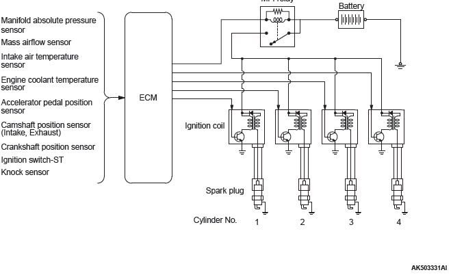
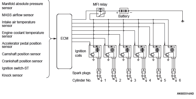
This system is equipped with four <2.4L> or six <3.0L> ignition coils with built-in power transistors for each of the cylinders.
Interruption of the primary current flowing in the primary side of an ignition coil generates a high voltage in the secondary side of ignition coil. The high voltage thus generated is applied to the spark plugs to generate sparks. The engine control module (ECM) turns the power transistors inside the ignition coils alternately on and off. This causes the primary currents in the ignition coils to be alternately interrupted and allowed to flow to fire the cylinders in the order 1-3-4-2 <2.4L> or 1-2-3-4-5-6 <3.0L>.
The ECM determines which ignition coil should be controlled by means of the signals from the camshaft position sensor and the crank angle sensor. It also detects the crankshaft position, in order to provide ignition at the most appropriate timing in response to the engine operation conditions.
When the engine is cold or running at high altitudes, the ignition timing is slightly advanced to provide optimum performance. Furthermore, if knocking occurs, the ignition timing is gradually retarded until knocking ceases.
SYSTEM DIAGRAM
<2.4L>
<3.0L>
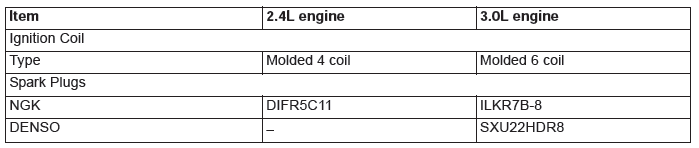
GENERAL SPECIFICATIONS
SERVICE SPECIFICATIONS
SPECIAL TOOL
ON-VEHICLE SERVICE
KNOCK CONTROL SYSTEM CHECK
Check the knock sensor circuit if diagnostic trouble code, No. P0326, P0327, P0328, P0331, P0332 or P0333 is shown.
IGNITION COIL CHECK
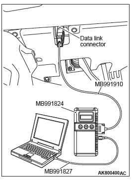
Required Special Tool:
MB991958: Scan Tool (M.U.T-III Sub Assembly)
- MB991824: V.C.I.
- MB991827: M.U.T.-III USB Cable
- MB991910: M.U.T.-III Main Harness A
CAUTION
To prevent damage to scan tool MB991958, always turn the ignition switch to the "LOCK" (OFF) position before connecting or disconnecting scan tool MB991958.
NOTE: It is impossible to carry out an easy check using a circuit tester because a diode and so on are integrated into the inside circuit of this ignition coil. Accordingly, check the ignition coil in the following procedure.
1. Make sure the diagnosis codes are not stored using scan tool MB991958. If stored, record the code No. Carry out the troubleshooting for the stored codes and solve the problems even if not related to the ignition.
2. Disconnect the injector connectors on all of the cylinders.
3. Disconnect the ignition coil connector.
4. Remove the ignition coil and install a good spark plug to the ignition coil.
5. Connect the ignition coil connector.
6. Ground the side electrode of the spark plug and crank the engine.
7. Check that spark is produced between the electrodes of the spark plug.
8. If the spark plug has weak spark or no spark, carry out the same check using a good ignition coil. If there is strong spark on this check with a good ignition coil, it becomes clear there is a problem with the ignition coil. Replace the ignition coil with a new one. If there is no spark on this check with a good ignition coil, there is probably a problem with the ignition circuit. Check the ignition circuit.
9. Using scan tool MB991958, make sure whether the diagnosis codes are stored due to the check, or not. Except the codes stored in Step 1, clear the codes all together if they are present. And then, carry out the troubleshooting about the codes recorded.
10.Select "Mode $0A" from "Special Function" of Scan tool MB991958. Check whether the permanent-DTC (PDTC) is stored or not. <3.0 L Engine> If stored, clear the PDTC.
CAUTION
To prevent damage to scan tool MB991958, always turn the ignition switch to the "LOCK" (OFF) position before connecting or disconnecting scan tool MB991958.
11.Disconnect scan tool MB991958 to the data link connector.
SPARK PLUG TEST
1. Remove the spark plug and connect to the ignition coil.
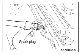
2. Ground the spark plug outer electrode (body), and crank the engine.
Check that there is an electrical discharge between the electrodes at this time.
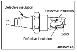
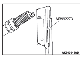
SPARK PLUG CHECK AND CLEANING
Required Special Tool
MB992273: Spark Plug Brush
CAUTION
- Never attempt to adjust the gap of the iridium plug.
- Do not attempt to clean the iridium plug using a wire
brush because it may result in damage to the electrode.
When the iridium plug is cleaned, use a plug cleaner, sand blast type, or special tool MB992273.
NOTE: Obey the maintenance interval of the vehicle for the spark plug replacement. If the plug gap and insulation resistance are normal, check the plug state and clean it if necessary.
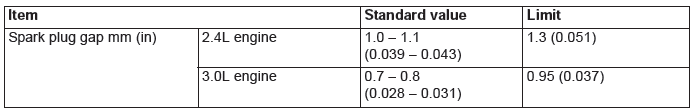
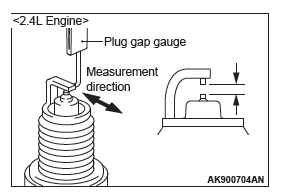
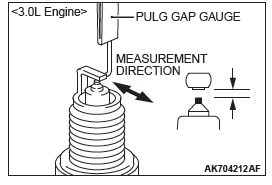
SPARK PLUG GAP CHECK
Check the plug gap with the wire type plug gauge. Replace it if the limit is exceeded.
Standard value:
1.0 − 1.1 mm (0.039 − 0.043 inch) <2.4L Engine>
0.7 − 0.8 mm (0.028 − 0.031 inch) <3.0L Engine>
Limit:
1.3 mm (0.051 inch) <2.4L Engine>
0.95 mm (0.037 inch) <3.0L Engine>
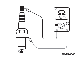
SPARK PLUG INSULATION RESISTANCE CHECK
1. Measure the insulation resistance of the spark plug. If the insulation resistance of the spark plug is under the limited value, clean the spark plug.
2. After cleaning, measure the insulation resistance again.
Replace the plug unless it is within the limited value.
Limit: Minimum 10 MΩ
SPARK PLUG CLEANING
NOTE: Using a sand blast type plug cleaner, is recommended for the spark plug cleaning.
<When a sand blast type plug cleaner is used>
Cleaning must be carried out within 20 seconds to protect the electrode.
<When special tool MB992273 is used>
1. Sufficiently apply the brake cleaner to the plug end.
NOTE: Repeatedly applying the brake cleaner is acceptable during the cleaning.
2. Using special tool MB992273, intensively clean the electrode for 1 to 2 minutes.
NOTE: Even if using strong force, the electrode is not damaged.
NOTE: In case of insufficient cleaning, it is permissible to take longer than 2 minutes for cleaning.
3. After the cleaning, sufficiently remove and then dry both of the carbon and the brake cleaner on the plug, using a waste cloth or air blowing.
CAMSHAFT POSITION SENSOR CHECK
Refer to GROUP 13A, Multiport Fuel Injection (MFI) <2.4L Engine> − Multiport Fuel Injection (MFI) Diagnosis − Diagnostic Trouble Code Procedures − DTC P0340: Camshaft Position Sensor Circuit. <2.4L> Refer to GROUP 13B, Multiport Fuel Injection (MFI) <3.0L Engine> − Multiport Fuel Injection (MFI) Diagnosis − Diagnostic Trouble Code Procedures − DTC P0340: Camshaft Position Sensor Circuit. <3.0L>
CRANKSHAFT POSITION SENSOR CHECK
Refer to GROUP 13A, Multiport Fuel Injection (MFI) <2.4L Engine> − Multiport Fuel Injection (MFI) Diagnosis − Diagnostic Trouble Code Procedures − DTC P0335: Crankshaft Position Sensor Circuit. <2.4L> Refer to GROUP 13B, Multiport Fuel Injection (MFI) <3.0L Engine> − Multiport Fuel Injection (MFI) Diagnosis − Diagnostic Trouble Code Procedures − DTC P0335: Crankshaft Position Sensor Circuit. <3.0L>
IGNITION COIL
REMOVAL AND INSTALLATION <2.4L ENGINE>
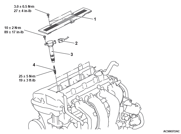
Removal steps
- Cylinder head cover center cover
- Ignition coil connector connection
- Ignition coil
- Spark plug
REMOVAL AND INSTALLATION <3.0L ENGINE>
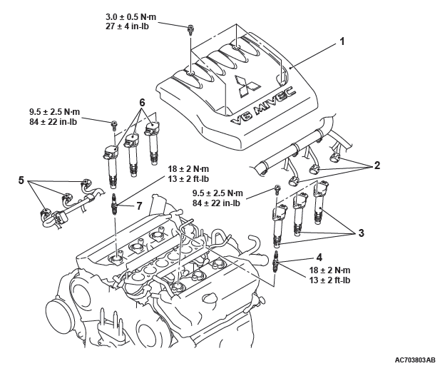
Removal steps
- Engine cover
- Ignition coil connector connection (Left bank)
- Ignition coil (Left bank)
- Spark plug (Left bank)
- Intake manifold plenum
- Ignition coil connector connection (Right bank)
- Ignition coil (Right bank)
- Spark plug (Right bank)
CAMSHAFT POSITION SENSOR
REMOVAL AND INSTALLATION <2.4L ENGINE>
Removal steps <Exhaust side>
- Engine hanger
- Exhaust camshaft position sensor connector connection
- Exhaust camshaft position sensor
- O-ring
Removal steps <Intake side>
- Air cleaner cover and air cleaner intake hose
- Control harness clamp
- Emission vacuum hose and pipe assembly mounting bolt
- Intake camshaft position sensor connector connection
- Intake camshaft position sensor
- O-ring
REMOVAL AND INSTALLATION <3.0L ENGINE>
Pre-removal Operation
- Engine Coolant Draining
- Battery and Battery Tray Removal
Post-installation Operation
- Battery and Battery Tray Installation
- Engine Coolant Refilling
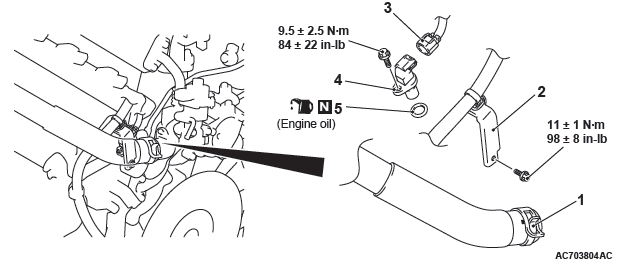
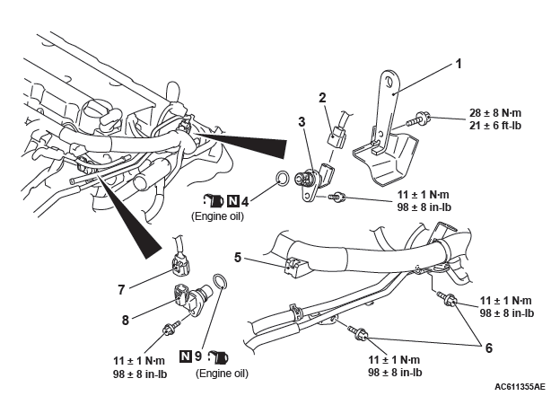
Removal steps
- Radiator upper hose connection
- Harness bracket
- Camshaft position sensor connector connection
- Camshaft position sensor
- O-ring
REMOVAL SERVICE POINT
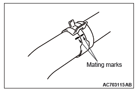
RADIATOR UPPER HOSE DISCONNECTION
Make mating marks on the radiator upper hose and the hose clamp. Disconnect the radiator upper hose.
INSTALLATION SERVICE POINT
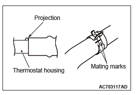
RADIATOR UPPER HOSE CONNECTION
1. Insert radiator upper hose as far as the projection of the thermostat housing.
2. Align the mating marks on the radiator upper hose and hose clamp, and then connect the radiator upper hose.
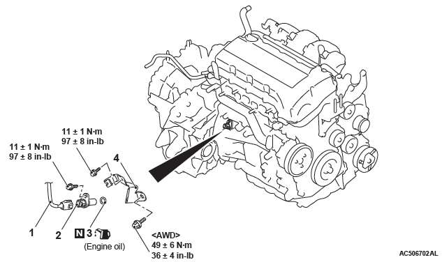
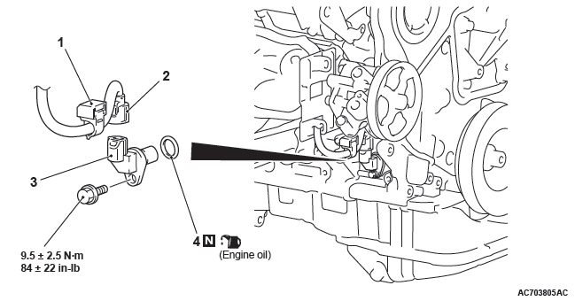
CRANKSHAFT POSITION SENSOR
REMOVAL AND INSTALLATION <2.4L ENGINE>
Pre-removal and post-installation operation
- Air Cleaner Assembly Removal and Installation
Removal steps
- Crankshaft position sensor connector connection
- Crankshaft position sensor
- O-ring
- Exhaust manifold bracket
- Crankshaft position sensor cover
REMOVAL AND INSTALLATION <3.0L ENGINE>
Pre-removal operation
- Engine Room Side Cover (RH) Removal
- Driveshaft Assembly (RH) Removal <Vehicles with S-AWC>
Post-installation operation
- Driveshaft Assembly (RH) Installation <Vehicles with S-AWC>
- Engine Room Side Cover (RH) Installation
Removal steps
- Harness clamp
- Crankshaft position sensor connector connection
- Crankshaft position sensor
- O-ring
KNOCK SENSOR
REMOVAL AND INSTALLATION <2.4L ENGINE>
CAUTION
- When the knock sensor replacement is performed, use scan tool MB991958 to initialize the learning value.
- Do not drop or hit the knock sensor against other components. Internal damage may result, and the knock sensor will need to be replaced.
Pre-removal and post-installation operation
- Intake Manifold Assembly Removal and Installation.
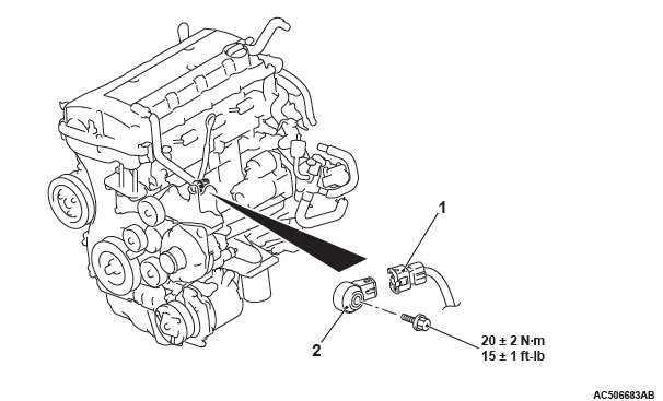
Removal steps
- Knock sensor connector connection
- Knock sensor
REMOVAL AND INSTALLATION <3.0L ENGINE>
CAUTION
- When the knock sensor replacement is performed, use scan tool MB991958 to initialize the learning value.
- Do not drop or hit the knock sensor against other components. Internal damage may result, and the knock sensor will need to be replaced.
Pre-removal and Post-installation Operation
- Intake Manifold Removal and Installation.
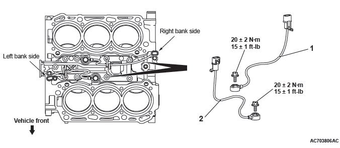
Removal steps
- Right bank knock sensor
- Left bank knock sensor
READ NEXT:
 Engine Control
GENERAL INFORMATION
For the accelerator system, the electronic throttle
valve control system, disposing of the accelerator
cable, is adopted.
This system determines the amount of pressure
applied to
SEE MORE:
Diagnostic Item 24-25
DIAGNOSTIC ITEM 24: Short to power supply or ground in both CAN_H and
CAN_L lines of the
CAN-B bus lines.
CAUTION
When servicing a CAN bus line, ground yourself
by touching a metal object such as an unpainted
water pipe. If you fail to do so, a component connected
to the CAN bus line may be damage
Valve Stem Seal
REMOVAL AND INSTALLATION
CAUTION
*Remove and assemble the marked parts in each cylinder unit.
Pre-removal operation
Engine Room Under Cover Front B and Engine Room Side
Cover (RH) Removal
Engine Oil Draining
Rocker Cover Assembly Removal
Engine Oil Pan Removal
Timing Chain Removal
Post-in
