Mitsubishi Outlander: Power Steering Oil Pump Assembly
REMOVAL AND INSTALLATION
Pre-removal operation
- Power Steering Fluid Draining
- Engine Upper Cover Removal
- Engine Room Side Cover (RH) Removal
- Generator and Others Belt Removal
Post-installation operation
- Generator and Others Belt Installation
- Generator and Others Belt Tension Check
- Engine Upper Cover Installation
- Engine Room Side Cover (RH) Installation
- Power Steering Fluid Refilling and Bleeding
<2.4L Engine>
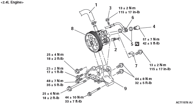
Removal steps
- Suction hose connection
- Pressure switch connector connection
- Clamp bolt
- Eye bolt
- Gasket
- Pressure hose assembly connection
- Harness bracket
- Oil pump assembly
- Oil pump bracket
<3.0L Engine>
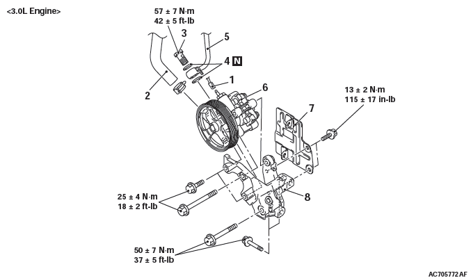
Removal steps
- Pressure switch connector connection
- Suction hose connection
- Eye bolt
- Gasket
- Pressure hose assembly connection
- Oil pump assembly
- Heat protector
- Power steering pump bracket
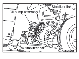
REMOVAL SERVICE POINT
OIL PUMP ASSEMBLY REMOVAL
When removing the oil pump assembly, remove the stabilizer link and stabilizer bar bracket, shift the stabilizer bar to the left of the vehicle, and then remove the assembly from the front wheel house (right side).
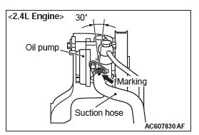
INSTALLATION SERVICE POINT
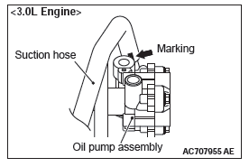
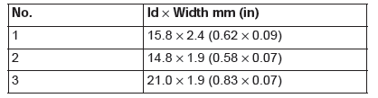
SUCTION HOSE CONNECTION
Align the suction hose marking within the area shown in the figure and connect the suction hose.
INSPECTION
- Check the drive belt for cracks.
- Check the pulley for uneven rotation.
DISASSEMBLY AND ASSEMBLY
CAUTION Do not use ATF-SP II M and ATF-SP III for the power steering fluid.
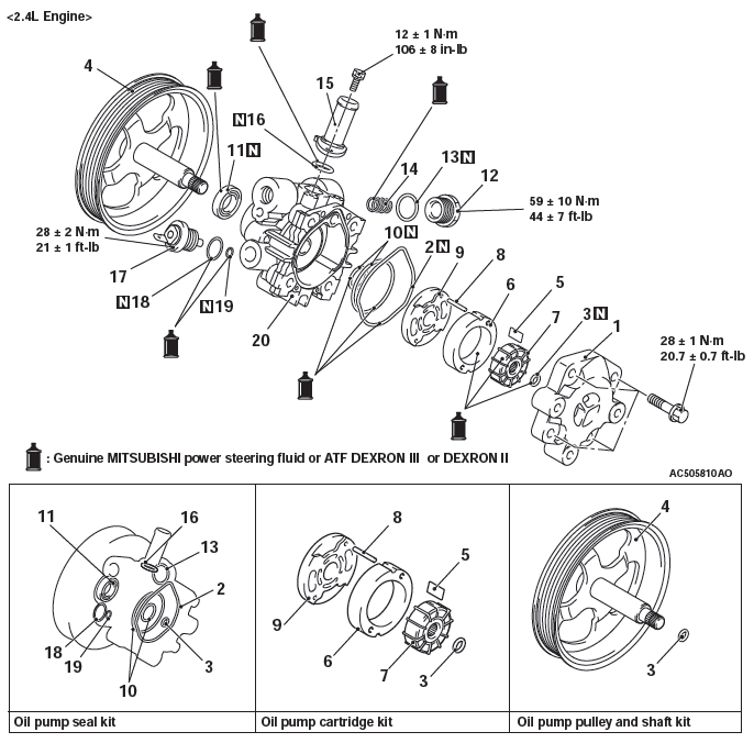
<2.4L Engine>
<3.0L Engine>
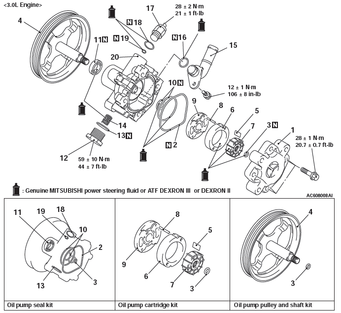
Disassembly steps
- Pump cover
- O-ring
- Snap ring
- Pulley and shaft
- Vane
- Cam ring
- Rotor
- Pin
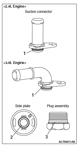
- Side plate
- O-ring
- Oil seal
- Plug assembly
- O-ring
- Flow control spring
- Suction connector
- O-ring
- Terminal assembly
- O-ring
- O-ring
- Oil pump case
Required Special Tools:
- MB990938: Bar (Snap-in type)
- MB991203: Oil Seal and Bearing Installer
ASSEMBLY SERVICE POINTS
O-RING INSTALLATION
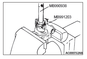
OIL SEAL INSTALLATION
Use the following special tools to install the oil seal.
- Installer special tool bar (MB990938) [Including in the special tool bearing and oil seal installer set (MB990925) ]
- Special tool oil seal and bearing installer (MB991203)
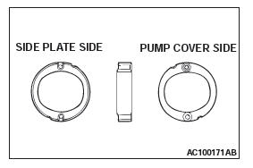
CAM RING INSTALLATION
CAUTION Be sure to install the cam ring in the correct direction as shown.
Install the cam ring as shown in the illustration.
INSPECTION
- Check the pulley and shaft for wear or damage.
- Check the rotor and vane groove for "stepped" wear.
- Check the contact surface of cam ring and vanes for "stepped" wear.
- Check the vanes for damage.
READ NEXT:
 Power Steering Hoses
REMOVAL AND INSTALLATION
Pre-removal operation
Power Steering Fluid Draining
Engine room Under Cover Front (A,B,C), Engine room
Side Cover, Engine room Under Cover Rear Removal
Propeller Shaft A
CVT
General Information
F1CJA, W1CJA model has been established.
TRANSAXLE
The transaxle consists of the torque converter and
gear train. The three-element, one-stage, two-phase
type torque converter wit
SEE MORE:
Camshaft
REMOVAL AND INSTALLATION
Pre-removal Operation
Engine Room Under Cover Front A, B and Engine Room
Side Cover (RH) Removal.
Air Cleaner Assembly Removal.
Strut Tower Bar Removal.
Post-installation Operation
Strut Tower Bar Installation.
Air Cleaner Assembly Installation.
Engine Room Under C
Parking brake
To park the vehicle, first bring in to a complete stop, fully engage the parking
brake.
To apply
1- Pull the lever up without pushing the button at the end of hand grip.
To release
1- Pull the lever up slightly.
2- Push the button at the end of hand grip.
3- Push the lever downward.
C
