Mitsubishi Outlander: CVT
General Information
F1CJA, W1CJA model has been established.
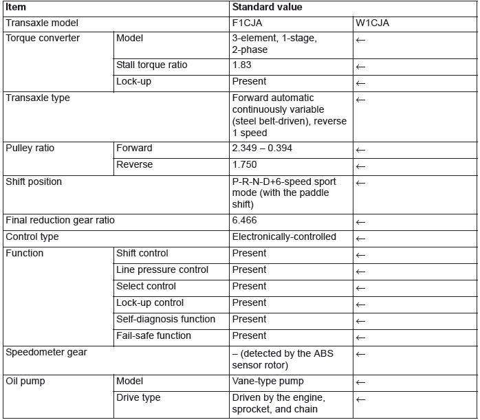
TRANSAXLE
The transaxle consists of the torque converter and gear train. The three-element, one-stage, two-phase type torque converter with a built-in torque converter clutch has been adopted. The gear train of F1CJA, W1CJA transaxle consists of 1 set of multi-disc type clutches, 1 set of multi-disc type brakes, and 1 set of planetary gears which are composed of a sun gear, carrier, annulus gear, 2 sets of pulleys and 1 set of steel belts.
TRANSAXLE CONFIGURATION DRAWING
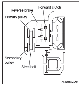
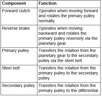
COMPONENTS AND FUNCTIONS
SECTIONAL VIEW
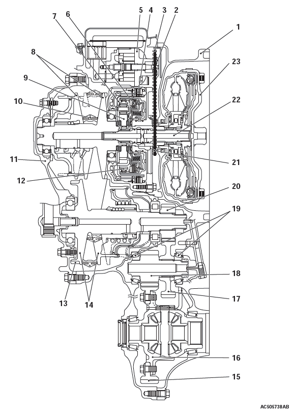
- Converter housing
- Driven sprocket
- Chain
- Reverse brake
- Oil pump
- Forward clutch
- Planet carrier
- Primary pulley
- Sun gear
- Steel belt
- Side cover
- Internal gear
- Parking gear
- Secondary pulley
- Final gear
- Differential case
- Idler gear
- Reduction gear
- Taper roller bearing
- Output gear
- Drive sprocket
- Input shaft
- Torque converter
ELECTRONICALLY-CONTROLLED SYSTEM
INVECS-III CONTROL
INVECS-III has been newly developed based on INVECS-II utilizing continuous variable characteristics of CVT.
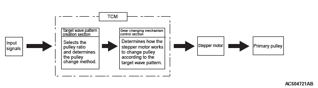
To select the pulley ratio which can provide the driving force corresponding to the driver's intention and vehicle conditions, TCM selects the optimal pulley ratio and determines the shift strategy to obtain it by detecting the vehicle driving conditions such as the vehicle speed, accelerator angle. Then, it outputs the command to the stepper motor, controls in/out flow of the line pressure to/from the primary pulley, positions the movable pulley of the primary pulley, and controls the gear ratio.
ENGINE BRAKE FEATURE ON THE DESCENDING SLOPE
Pulley ratio is controlled to obtain the engine brake suitable for the driver's feelings.
Engine brake learning feature on the descending slope
Learning compensation is made to meet the tastes of a driver by judging the amount of the engine brake from the application of the accelerator or the brake.
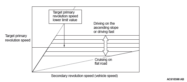
DRIVING FEATURE ON THE ASCENDING SLOPE
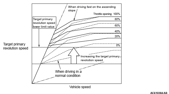
If the foot leaves the accelerator pedal during driving on the ascending slope (called lift foot), driving capability is secured by preventing excessive upshifting.
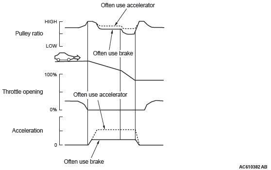
Learning feature corresponding to tastes and habits of drivers
Ratio patterns are continuously switched according to the driving method of a driver.
SYSTEM CONSTRUCTION DIAGRAM
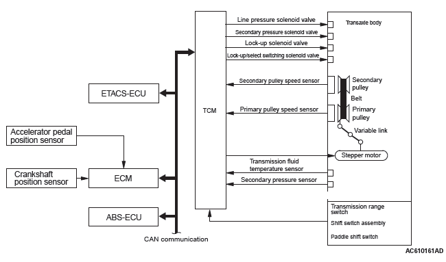
RATIO PATTERN
<D RANGE>
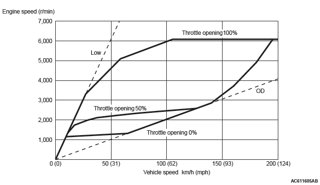
The shift change is performed in the entire shift range from the lowest to the highest pulley ratio.
<SPORT MODE>
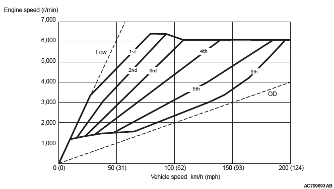
When the sport mode is switched ON with the selector lever or paddle shift, the fixed shifting line is determined. The upshift/downshift operation enables to shift in steps according to the predetermined shifting line, providing M/T-like shifting. The 6-speed transmission which is suitable for sporty driving is adopted.
DIRECT CONTROL (TORQUE CONVERTER CLUTCH CONTROL)
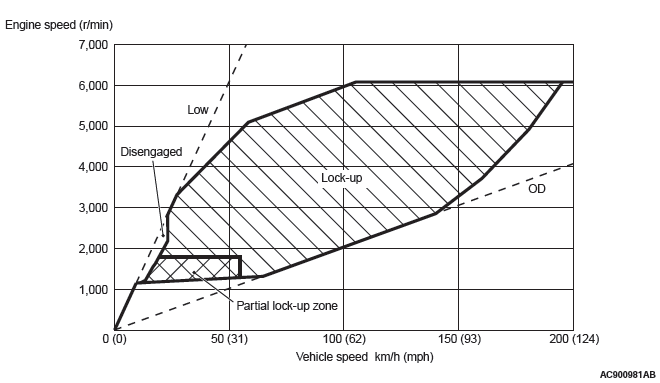
By carefully controlling the direct operating pressure depending on the driving conditions, the shock-free direct operation from low speed has been achieved.
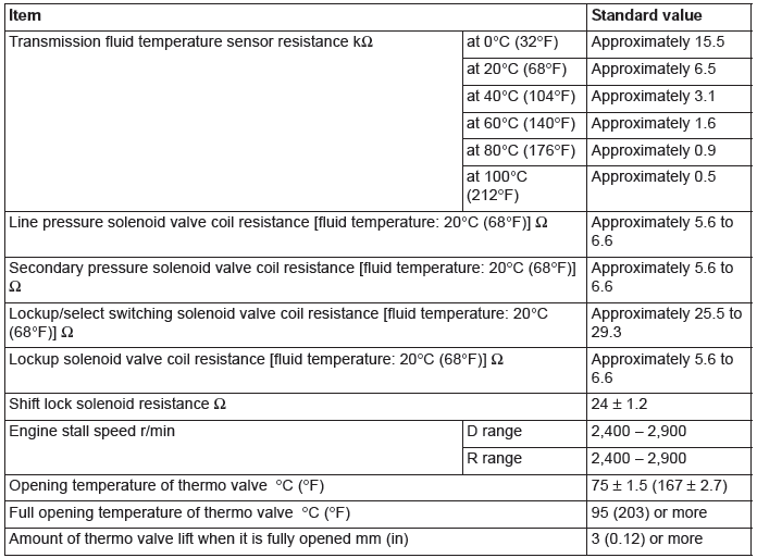
Service Specifications
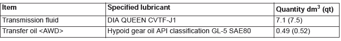
Lubricants
Diagnosis
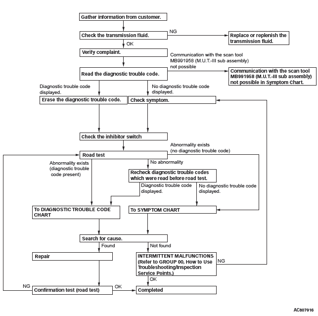
DIAGNOSTIC TROUBLESHOOTING FLOW
INTRODUCTION TO CVT DIAGNOSIS
The CVT can exhibit any of the following symptoms: noise or vibration is generated, Transmission fluid leaks, the vehicle does not move forward or backward.
The causes of these symptoms could come from: Incorrect mounting, the Transmission fluid may be low, or a component of the transaxle may be faulty.
The following items are suspected as causes for the INVECS-III troubles: malfunction of the TCM, the sensors, the switches, the harness or connectors.
CVT DIAGNOSTIC TROUBLESHOOTING STRATEGY
Use these steps to plan your diagnostic strategy. If you follow them carefully, you will find most CVT malfunctions.
1. Gather as much information as possible about the complaint from the customer.
2. Verify that the condition described by the customer exists.
3. Check the vehicle for any CVT Diagnostic Trouble Codes (DTCs).
4. If you can not verify the condition and there are no DTCs, the malfunction is intermittent. For information on how to cope with intermittent malfunctions, refer to GROUP 00, How to Use Troubleshooting/Inspection Service Points − How to Cope with Intermittent Malfunction.
5. If you can verify the condition but there are no DTCs, or the system can not communicate with scan tool, refer to the Symptom Chart.
6. If there is a DTC, record the number of the code, then erase the code from memory using scan tool.
7. Reconfirm the symptom with a Road Test.
8. If a DTC is set again, go to the Inspection Chart for Diagnostic Trouble Codes.
9. If a DTC is not set again, the malfunction is intermittent. For information on how to cope with intermittent malfunctions, refer to GROUP 00, How to Use Troubleshooting/Inspection Service Points − How to Cope with Intermittent Malfunction.
10.After repairs are completed, conduct a Road Test duplicating the complaint conditions to confirm the malfunction has been eliminated.
- Diagnostic Function
- Diagnostic Trouble Code Procedures
- Symptom Procedures
- On-vehicle Service
- Transaxle Control
- Transaxle Assembly
READ NEXT:
 Diagnostic Function
WARNING INDICATOR
When any malfunction occurs in the items related to the CVT
system, which are described below, the symbol (A) continues
being displayed in the information screen in the multi informa
DTC P0703, P0705, P0711, P0712, P0713, P0715, P0720, P0725, P0740,
P0741, P0745
DTC P0703: Malfunction of Stoplight Switch
Stoplight switch system circuit
DIAGNOSTIC FUNCTION
TCM detects malfunction using the stoplight switch
signal sent from the ETACS-ECU.
DESCRIPTIONS OF MON
SEE MORE:
On-vehicle Service
ID CODES REGISTRATION PROCEDURE
REGISTRATION USING SCAN TOOL MB991958 (M.U.T.-III SUB ASSEMBLY)
Required Special Tools:
MB991958 Scan Tool (M.U.T.-III Sub Assembly)
MB991824: Vehicle Communication Interface (V.C.I.)
MB991827 M.U.T.-III USB Cable
MB991910 M.U.T.-III Main Harness A
By operating
Installation of accessories
We recommend you to consult your MITSUBISHI MOTORS Authorised Service Point.
● The installation of accessories, optional components, etc., should only be
carried out within the limits prescribed by law in your country, and in accordance
with the guidelines and warnings contained within th
