Mitsubishi Outlander: Transaxle Assembly
REMOVAL AND INSTALLATION
CAUTION The parts indicated by the * are the bolts with friction coefficient stabilizer. In removal, ensure there is no damage, clean dust and soiling from bearing and thread surfaces, and tighten them to the specified torque.
Pre-removal operation
- Engine compartment under cover front A, B and side cover removal
- Transmission fluid draining
- Air cleaner bracket removal
- Battery and Battery Tray Removal
- ECM removal
- Wiper arm blade assembly and front deck garnish removal
- Strut Tower Bar Removal
- Drive shaft removal
Post-installation operation
- Drive shaft installation
- Strut Tower Bar Installation
- Wiper arm and blade assembly and front deck garnish installation
- Battery and battery tray installation
- ECM installation
- Air cleaner assembly installation
- Engine compartment under cover and side cover installation
- Transmission fluid refilling
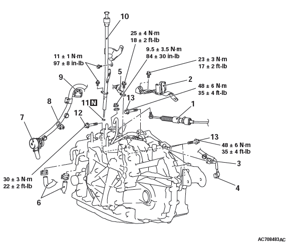
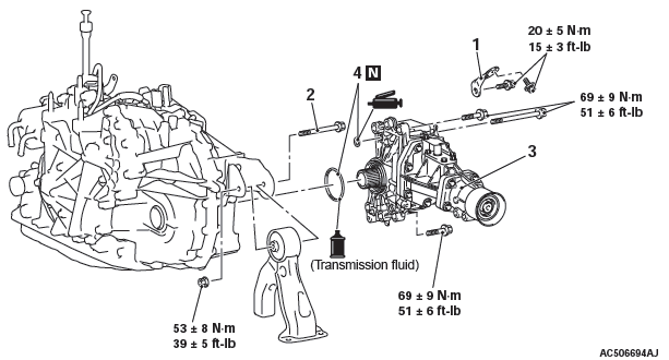
Removal steps
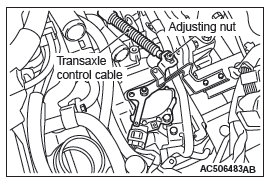
- Transaxle control cable connection
- Transaxle control bracket
- Secondary pulley rotation sensor harness connector
- Crank angle sensor harness connector
- Battery ground
- Transmission fluid cooler hose
- Transmission fluid cooler hose assembly A connection.
- CVT assembly connector
- Primary pulley rotation sensor connector
- Transmission range switch connector
- Oil filler tube assembly
- Water tube assembly
- O-ring
- Starter mounting bolt
- Transaxle assembly upper part coupling bolt
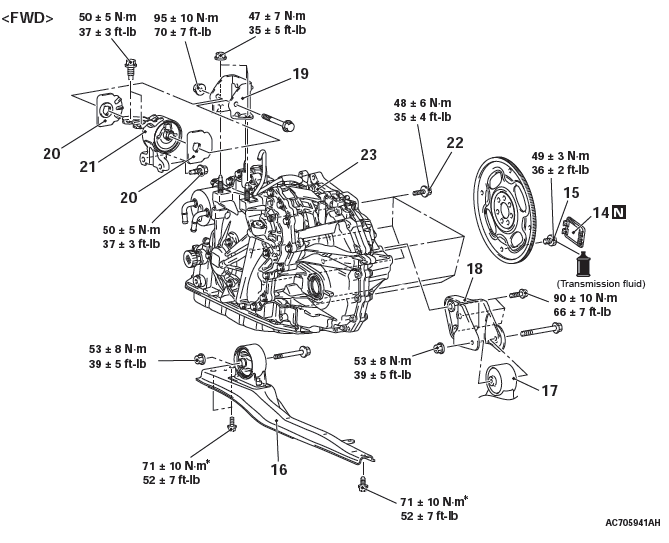
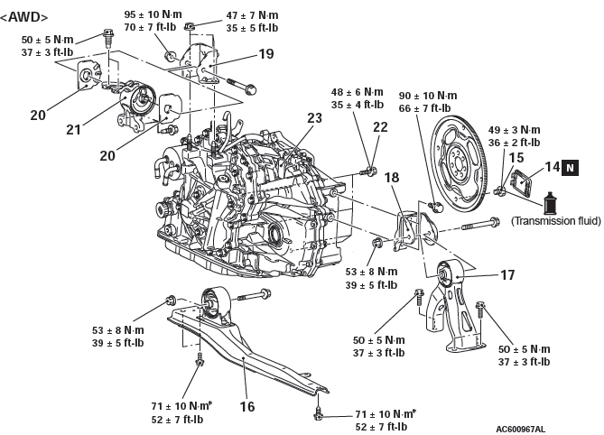
Removal steps
- Cover
- Torque converter and drive plate coupling bolt
- Center member assembly
- Transfer assembly <AWD>
- Rear rolling stopper connection <FWD>, Rear rolling stopper <AWD>
- Transaxle case rear roll stopper bracket
- Transaxle mounting bracket
- Transaxle mounting insulator stopper
- Transaxle mounting insulator
- Engine assembly holding
- Transaxle assembly lower part coupling bolt
- Transaxle assembly
REMOVAL SERVICE POINTS
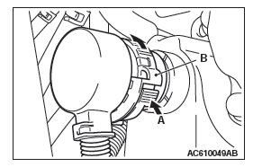
CVT ASSEMBLY CONNECTOR REMOVAL
While pushing the part A shown in the figure, and turn the part B counterclockwise to disconnect the CVT assembly connector.
TRANSAXLE ASSEMBLY UPPER PART COUPLING BOLT REMOVAL
Only loosen the bolts from the engine and transaxle assembly (do not remove).
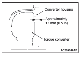
TORQUE CONVERTER AND DRIVE PLATE COUPLING BOLT REMOVAL
1. Remove the coupling bolts while turning the crankshaft.
2. Fully push the torque converter into the transaxle side so that it does not remain on the engine side.
TRANSAXLE MOUNTING BRACKET REMOVAL
1. Place a garage jack against the transaxle case with a piece of wood in between to support the engine and transaxle assembly.
2. Operate a garage jack so that the weight of the engine and transaxle assembly is not applied to the transaxle mounting insulator, and remove the transaxle mounting bracket.
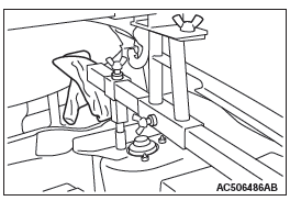
ENGINE ASSEMBLY HOLDING
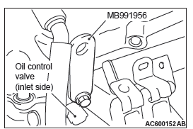
1. Install special tool engine hanger plate (MB991956) to the cylinder head.
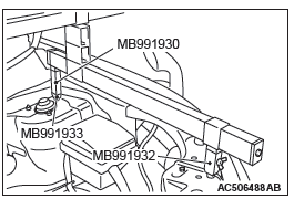
2. <When special tool engine hanger (MB991928) is used>
- Assemble the engine hanger (Special tool: MB991928).
(Set the components below to the base hanger.)
- Slide bracket (HI)
- Foot x 2 (standard) (MB991932)
- Foot x 2 (short) (MB991933)
- Joint x 2 (90) (MB991930)
- Set the feet of the special tool as shown in the figure.
NOTE: Adjust the engine hanger balance by sliding the slide bracket (HI).
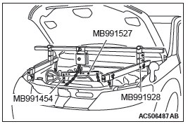
- Set the chains of special tool engine hanger (MB991527) and special tool engine hanger balancer (MB991454) to support the engine and transaxle assembly. Remove the garage jack and then remove the transaxle assembly upper part coupling bolts that have been loosened previously.
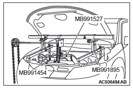
3. <When using special tool engine mechanical hanger (MB991895)>
- Set the foot of special tool engine mechanical hanger
(MB991895) as shown in the figure.
NOTE: Slide the front foot of special tool engine mechanical hanger (MB991895) to balance the engine hanger.
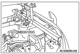
CAUTION Place rag between special tool engine mechanical hanger (MB991895) and the windshield to prevent the special tool from interfering with the windshield.
- Set the chains of special tool engine hanger (MB991527) and special tool engine hanger balancer (MB991454) to support the engine and transaxle assembly. Remove the garage jack and then remove the transaxle assembly upper part coupling bolts that have been loosened previously.
INSTALLATION SERVICE POINTS
TRANSAXLE ASSEMBLY INSTALLATION
Fully push the torque converter into the transaxle side, and then assemble the transaxle assembly to the engine.
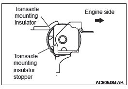
TRANSAXLE MOUNTING INSULATOR
STOPPER INSTALLATION
Install the transaxle mounting insulator stopper as shown in the figure.
TRANSAXLE CONTROL CABLE (TRANSAXLE SIDE) INSTALLATION
1. Move the selector lever to the "N" range.
2. Move the manual control lever to Neutral position.
3. Align the hole at the end of the manual control lever and the hole in the inhibitor switch body flange (section A − A).
NOTE: Insert a φ5 mm (0.2 inch) bar into the aligned holes in the transmission range switch body flange and on the tip of the manual control lever to position the transmission range switch body.
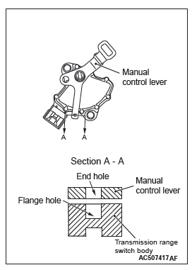
4. Use the adjusting nut to tighten the transmission control cable to the specified torque.
Tightening torque: 9.5 +- 3.5 N*m (84 +- 31 in-lb)
5. Make sure that the transmission-side ranges that are corresponding to the transmission range operate and function without fail.
Transfer Assembly <AWD>
REMOVAL AND INSTALLATION
Pre-removal and post-installation operation
- Under cover removal and installation
- Transmission fluid draining and refilling
- Transfer oil draining and refilling
- Front exhaust pipe removal and installation
- Propeller shaft removal and installation
- Center member removal and installation
- Drive shaft <RH> and output shaft removal and installation
Removal steps
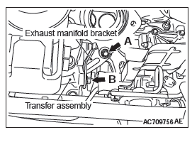
- Exhaust manifold bracket B
- Rear roll stopper center bolt
- Transfer assembly
- O-ring
REMOVAL SERVICE POINT
TRANSFER ASSEMBLY REMOVAL
Move the engine and transaxle assembly toward the front of the vehicle to make a gap between the engine/transaxle assembly and the crossmember. Pull out the transfer assembly through this gap.
INSTALLATION SERVICE POINT
EXHAUST MANIFOLD BRACKET B INSTALLATION
1. Make sure that the exhaust manifold bracket is closely contacted with the exhaust manifold and transfer assembly, and then temporarily tighten the bolts.
2. Tighten bolt A on the exhaust manifold side in the figure to the specified torque.
Tightening torque: 20 +- 5 N*m (15 +- 3 ft-lb)
3. Tighten bolt B on the transfer assembly side in the figure to the specified torque.
Tightening torque: 20 +- 5 N*m (15 +- 3 ft-lb)
Transaxle Control Module (TCM)
REMOVAL AND INSTALLATION
CAUTION To store the change gear ratio status of the CVT assembly in the TCM memory, drive the vehicle at 3 km/h or faster after replacing the TCM.
Pre-removal and post-installation operation
- Bottom cover assembly (passenger side) removal and installation
- Glove box assembly removal and installation
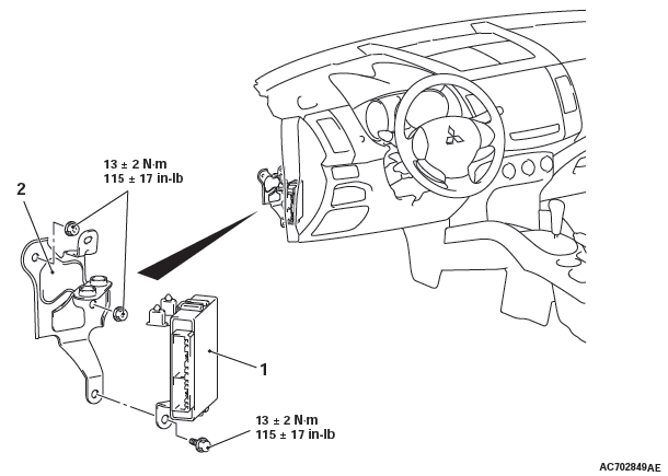
- TCM
- TCM bracket
Transmission Fluid Cooler and Cooler Line
REMOVAL AND INSTALLATION
Pre-removal and post-installation operation
- Engine room under cover front, engine room side cover
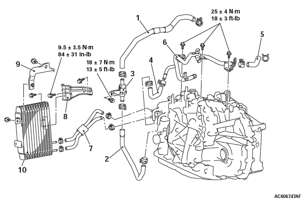
CVT fluid cooler line removal steps
- Water feed hose B
- Water feed hose A
- Thermo valve assembly
- Water return hose A
- Water return hose B
- Water tube assembly
- CVT fluid cooler hose assembly
- CVT fluid cooler bracket A
- CVT fluid cooler bracket B
- CVT fluid cooler assembly
THERMO VALVE CHECK
.1. Obtain a container filled with water and place the thermo valve in it with a stick [approximately 6 mm (0.24 inch) in diameter] inserted. Gradually warm up the water while stirring, and check that the thermo valve opening temperature is within the standard value. The stick rises when the thermo valve opens.
Standard value:
75 +- 1.5ºC (167 +- 2.7ºF)
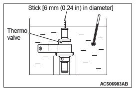
2. Warm up the water to the full-open temperature of the thermo valve, and check that the valve lift amount is within the standard value.
Standard value:
Full-open temperature 95ºC (203ºF) or more
Valve lift amount when it is fully opened:
3 mm (0.12 inch) or more
NOTE: Measure the height of the fully closed valve in advance, and then measure the valve height at fully open temperature to calculate the lift amount.
READ NEXT:
 Continuously
Variable
Transaxle
Overhaul
Continuously
Variable
Transaxle
Overhaul
General Information
TRANSAXLE MODELS
SECTIONAL VIEW <TRANSAXLE>
<F1CJA>
<W1CJA>
SECTIONAL VIEW <TRANSFER>
General Specifications
Service Specifications
Fastener Tightenin
Transaxle
DISASSEMBLY AND ASSEMBLY
CAUTION
Only use transmission fluid of the specified brand. Use of
transmission fluid other than specified
will impair driveability and CVT endurance, and may lead to bre
Forward Clutch
DISASSEMBLY AND ASSEMBLY
Disassembly steps
Snap ring
Internal gear
Snap ring
Snap ring
Seal ring (small)
Seal ring (big)
Input shaft
Forward clutch sub-assembly
DISASSEMBLY SERVICE POINT
SN
SEE MORE:
Manual transmission
The shift pattern is shown on the gearshift lever knob. Be sure to always fully
depress the clutch pedal before attempting to shift the lever.
CAUTION:
● Do not put the gearshift lever into the reverse position while the vehicle
is moving forward. Doing so could damage the transmission
Running-in recommendations
During the running-in period for the first 1,000 km (600 miles), it is advisable
to drive your new vehicle using the following precautions as a guideline to aid
long life as well as future economy and performance.
● Do not race the engine at high speeds.
● Avoid rapid starting, a
