Mitsubishi Outlander: DTC P0703, P0705, P0711, P0712, P0713, P0715, P0720, P0725, P0740, P0741, P0745
DTC P0703: Malfunction of Stoplight Switch
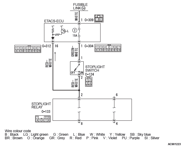
Stoplight switch system circuit
DIAGNOSTIC FUNCTION
TCM detects malfunction using the stoplight switch signal sent from the ETACS-ECU.
DESCRIPTIONS OF MONITOR METHODS
- Drive the vehicle at 30 km/h (19 mph) or more for 10 seconds, and then turn the ignition switch to the "LOCK" (OFF) position. In this sequential operation, no variation has been found in the stoplight switch input signal in two consecutive times.
MONITOR EXECUTION
- Continuous
MONITOR EXECUTION CONDITIONS (OTHER MONITOR AND SENSOR)
Other Monitor (There is no temporary DTC stored in memory for the item monitored below)
- Not applicable
Sensor (The sensor below is determined to be normal)
- Not applicable
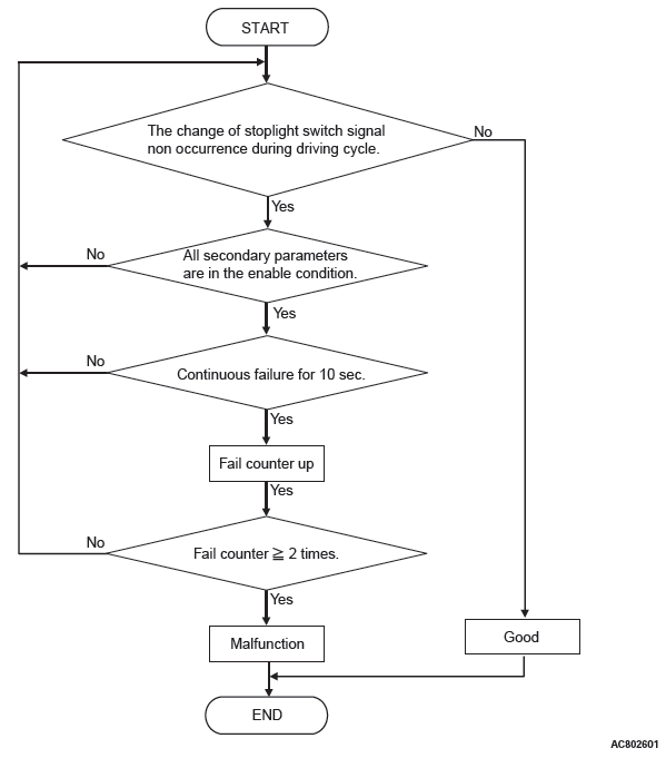
LOGIC FLOW CHARTS (Monitor Sequence)
DTC SET CONDITIONS
Check Conditions
- Vehicle speed: 30 km/h (19 mph) or more.
- Voltage of battery: 9 volts or more.
- Voltage of battery: 16 volts or less.
JUDGMENT CRITERIA
- The change of stoplight switch signal during driving cycle: no occurrence (10 seconds × 2 times).
OBD-II DRIVE CYCLE PATTERN
Drive the vehicle for 10 seconds or more at 30 km/h (19 mph) or higher (2 drive cycle)
PROBABLE CAUSES
- Malfunction of the CAN bus
- Malfunction of the stoplight switch
- Damaged wiring harness and connectors
- Malfunction of TCM
- Malfunction of ETACS-ECU
DIAGNOSTIC PROCEDURE
STEP 1. Using scan tool MB991958, diagnose the CAN bus line.
Use scan tool to perform the CAN bus diagnosis.
Q: Is the check result normal?
YES : Go to Step 2.
NO : Repair the CAN bus lines.
STEP 2. M.U.T.-III data list
Item 50: Brake switch
OK: The service data changes in response to the brake operation.
Q: Is the check result normal?
YES : Intermittent malfunction NO : Go to Step 3.
STEP 3. Check the following connector:
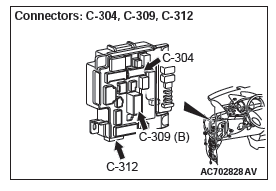
- C-304 ETACS-ECU connector
- C-312 ETACS-ECU connector
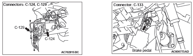
- C-124 Stoplight switch connector
- C-133 Stoplight relay connector
Check the contact status of the terminals.
Q: Is the check result normal?
YES : Go to Step 4.
NO : Repair the defective connector.
STEP 4. Stoplight Switch Check
Q: Is the check result normal?
YES : Go to Step 5.
NO : Replace the stoplight switch.
STEP 5. Check for open circuit in the wiring harness between the stoplight switch connector and the ETACS-ECU connector.
Between C-124 Stoplight switch connector (terminal No.1) and C-304 ETACS-ECU harness-side connector (terminal No.1)
Q: Is the check result normal?
YES : Go to Step 6.
NO : Repair the wiring harness.
STEP 6. Check for open circuit or short to ground in wiring harness between the stoplight switch connector and the ETACS-ECU
Between C-124 Stoplight switch connector (terminal No. 2) and C-312 ETACS-ECU harness-side connector (terminal No. 16)
Q: Is the check result normal?
YES : Go to Step 7.
NO : Repair the wiring harness.
STEP 7. Symptom recheck after erasing diagnostic trouble code
Q: Is the check result normal?
YES : Intermittent malfunction NO : Replace the ETACS-ECU, and then go to Step 8.
STEP 8. Symptom recheck after erasing diagnostic trouble code
Q: Is the check result normal?
YES : Intermittent malfunction NO : Replace TCM.
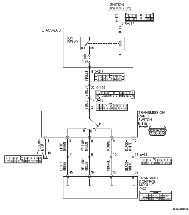
DTC P0705: Malfunction of Transmission Range Switch
Transmission range switch system circuit
DIAGNOSTIC FUNCTION
TCM monitors the signal from the transmission range switch, and determines if the abnormal input is present or not.
DESCRIPTIONS OF MONITOR METHODS
- TCM does not detects the inhibitor switch input signal for 5 seconds when the vehicle speed is 1 km/h (0.6 mph) or more for 10 seconds continuously.
- TCM detects the multiple inputs from the transmission range switch for 2 seconds.
MONITOR EXECUTION
- Vehicle speed (no-transmission range switch signal input):1km/h (0.6 mph) or more for 10 seconds continuously
- Vehicle speed (transmission range switch signal multiple input) : No conditions
- Throttle valve opening : 1/8 or more
- Engine speed : 450 r/min or more
MONITOR EXECUTION CONDITIONS (OTHER MONITOR AND SENSOR)
Other Monitor (There is no temporary DTC stored in memory for the item monitored below)
- P0715: Malfunction of primary pulley speed sensor
- P0720: Malfunction of secondary pulley speed sensor
- P0725: Malfunction of engine speed
- P0741: Abnormality in lockup function
- P0746: Abnormality in hydraulic control system function
- P0841: Abnormality in line pressure sensor function
- P1706: Malfunction of throttle signal
Sensor (The sensor below is determined to be normal)
- Primary pulley speed sensor
- Secondary pulley speed sensor
- Accelerator pedal position sensor
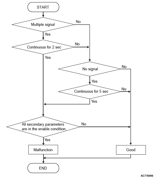
LOGIC FLOW CHARTS (Monitor Sequence)
DTC SET CONDITIONS
Check Conditions
- Vehicle speed over 1 km/h (0.6 mph): 10 seconds or more.
- Throttle position sensor voltage: 1.37 volts or more.
- Engine speed: 450 r/min or more.
- Voltage of battery: 9 volts or more.
- Voltage of battery: 16 volts or less.
JUDGMENT CRITERIA
- Transmission range switch: multiple signal. (2 seconds)
- Transmission range switch: no signal. (5 seconds)
OBD-II DRIVE CYCLE PATTERN
Transmission range: D (Drive the vehicle for 10 seconds or more while the accelerator opening angle is 20% or more)
PROBABLE CAUSES
- Malfunction of the transmission range switch
- Improper adjustment of transaxle control cable
- Damaged wiring harness and connectors
- Malfunction of TCM
DIAGNOSTIC PROCEDURE
STEP 1. M.U.T.-III data list
Item 49: Transmission range switch
Check that the service data changes when the selector lever is moved to all ranges.
OK: The service data changes in response to the selector lever operation.
Q: Is the check result normal?
YES : Intermittent malfunction
NO : Go to Step 2.
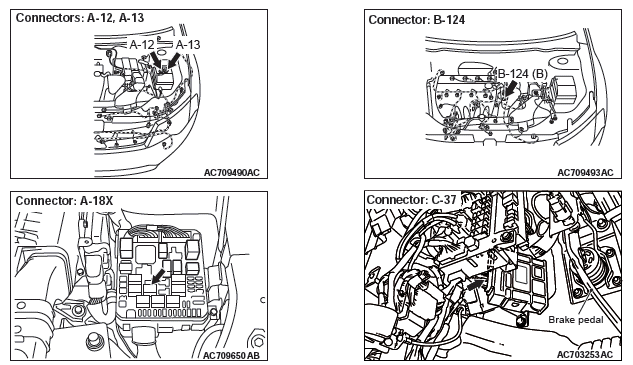
STEP 2. Check the following connector:
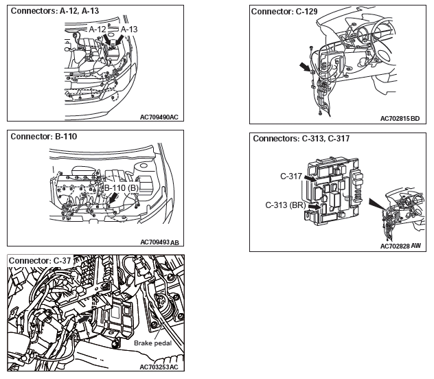
- B-110 transmission range switch connector
- C-37 TCM connector
Check the terminals for a contact status problem and internal short circuit.
Q: Is the check result normal?
YES : Go to Step 3.
NO : Repair the defective connector.
STEP 3. Check for open circuit in wiring harness between the ETACS-ECU connector and the transmission range switch connector
Between the C-313 ETACS-ECU connector (terminal No.4) and the B-110 transmission range switch connector (terminal No.3)
NOTE: Prior to the wiring harness inspection, check the intermediate connectors C-129 and A-13, and repair that if necessary.
Q: Is the check result normal?
YES : Go to Step 4.
NO : Repair the wiring harness.
STEP 4. Check for open circuit in the wiring harness between the transmission range switch connector and the TCM connector
- Between B-110 transmission range switch connector (terminal No.2) and C-37 TCM connector (terminal No.32)
- Between B-110 transmission range switch connector (terminal No.5) and C-37 TCM connector (terminal No.45)
- Between B-110 transmission range switch connector (terminal No.8) and C-37 TCM connector (terminal No.34)
- Between B-110 transmission range switch connector (terminal No.9) and C-37 TCM connector (terminal No.33)
Q: Is the check result normal?
YES : Go to Step 5.
NO : Repair the wiring harness.
STEP 5. Transmission range switch and control cable adjustment
Q: Is the check result normal?
YES : Go to Step 6.
NO : Adjust the transmission range switch and control cable.
STEP 6. Transmission range switch continuity check
Q: Is the check result normal?
YES : Go to Step 7.
NO : Replace the transmission range switch.
STEP 7. Symptom recheck after erasing diagnostic trouble code
Q: Is the check result normal? YES : Intermittent malfunction NO : Replace TCM.
DTC P0711: Malfunction of Transmission Fluid Temperature Sensor
DIAGNOSTIC FUNCTION
TCM conducts fault detection by monitoring the terminal voltage of the transmission fluid temperature sensor.
DESCRIPTIONS OF MONITOR METHODS
- Field A : Transmission fluid temperature is less
than -20ºC (-4ºF)
Field B : Transmission fluid temperature is -20ºC (-4ºF) or more and less than 0ºC (32ºF)
Field C : Transmission fluid temperature is 0ºC (32ºF) or more and less than 20ºC (68ºF)
When the transmission fluid temperature is kept at one of fields A, B and C above for 10 minutes.
MONITOR EXECUTION
- Transmission range: D
- Vehicle speed : 10 km (6.2 mph) or more
- Throttle valve opening : 1/8 or more
- Engine speed : 450 r/min or more
MONITOR EXECUTION CONDITIONS (OTHER MONITOR AND SENSOR)
Other Monitor (There is no temporary DTC stored in memory for the item monitored below)
- Not applicable
Sensor (The sensor below is determined to be normal)
- Not applicable
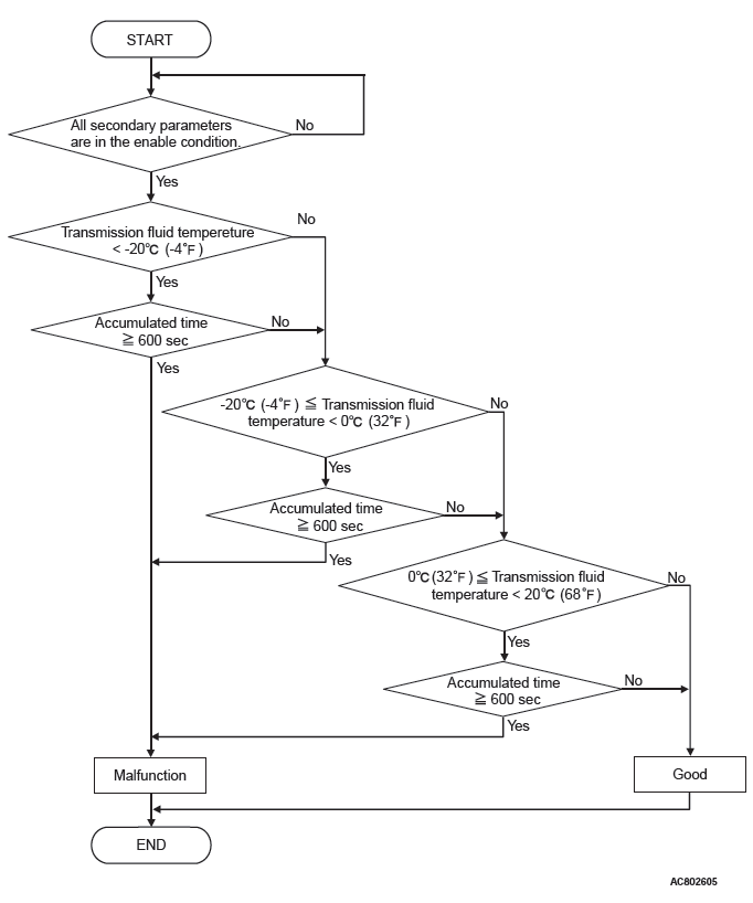
LOGIC FLOW CHARTS (Monitor Sequence)
DTC SET CONDITIONS
Check Conditions
- Transmission range switch position: D.
- Vehicle speed: 10 km/h (6.2 mph) or more.
- Throttle position sensor voltage: 1.37 volts or more.
- Engine speed: 450 r/min or more.
Judgment Criteria
- Transmission fluid temperature is less than -20ºC (-4ºF) for 600 seconds or more
- Transmission fluid temperature is -20ºC (-4ºF) or more and less than 0ºC (32ºF)for 600 seconds or more
- Transmission fluid temperature is 0ºC (32ºF) or more and less than 20ºC (68ºF) for 600 seconds or more
OBD-II DRIVE CYCLE PATTERN
Transmission range: D (Drive the vehicle for 20 seconds or more while the accelerator opening angle is 20% or more)
PROBABLE CAUSES
- Malfunction of transmission fluid temperature sensor
- Malfunction of transmission fluid cooler piping and oil pump
- Malfunction of TCM
DIAGNOSTIC PROCEDURE
STEP 1. Transmission fluid cooler piping and oil pump check
Q: Is the check result normal?
YES : Go to Step 2.
NO : Repair the failure sections.
STEP 2. Transmission fluid temperature sensor check
Q: Is the check result normal?
YES : Go to Step 3.
NO : Replace the valve body assembly.
STEP 3. Symptom recheck after erasing diagnosis code
Q: Is the check result normal?
YES : Intermittent malfunction NO : Replace TCM.
DTC P0712: Malfunction of Transmission Fluid Temperature Sensor
(Short)
DTC P0713: Malfunction of Transmission Fluid Temperature Sensor (Open)
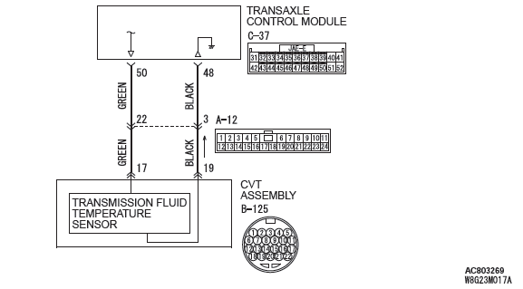
Transmission fluid temperature sensor system circuit
DIAGNOSTIC FUNCTION
TCM conducts fault detection by monitoring the terminal voltage of the transmission fluid temperature sensor.
- <P0712>: If transmission fluid temperature equals or exceeds specified value, TCM judges that transmission fluid temperature sensor has a failure.
- <P0713>: If transmission fluid temperature is below specified value even after test driving for more than the specified period, the TCM judges that the transmission fluid temperature sensor has a failure.
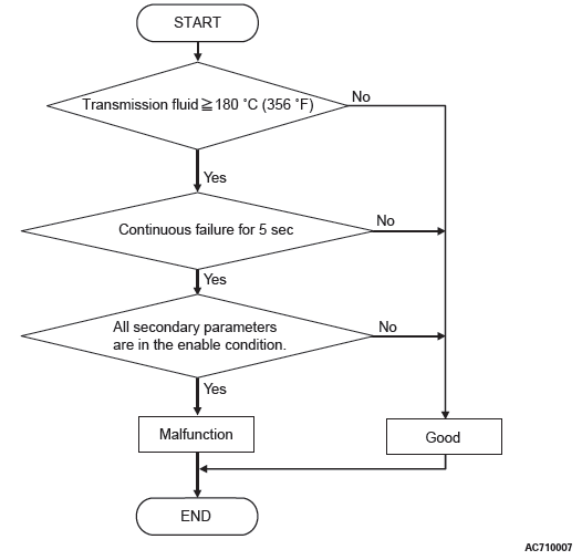
DESCRIPTIONS OF MONITOR METHODS <P0712>
- TCM detects the fluid temperature 180ºC (356ºF) or more for 5 seconds.
MONITOR EXECUTION <P0712>
- Continuous
MONITOR EXECUTION CONDITIONS (OTHER MONITOR AND SENSOR) <P0712>
Other Monitor (There is no temporary DTC stored in memory for the item monitored below)
- P0741: Abnormality in lockup function
- P0746: Abnormality in hydraulic control system function
- P0841: Abnormality in line pressure sensor function
Sensor (The sensor below is determined to be normal)
- Not applicable
LOGIC FLOW CHARTS (Monitor Sequence) <P0712>
DTC SET CONDITIONS <P0712>
Check Conditions
- Voltage of battery: 9 volts or more.
- Voltage of battery: 16 volts or less.
JUDGMENT CRITERIA
- Value of temperature of transmission fluid: 180ºC (356ºF) or more. (5 seconds)
OBD-II DRIVE CYCLE PATTERN <P0712>
Ignition switch : ON (start the engine and keep it for 10 seconds or more)
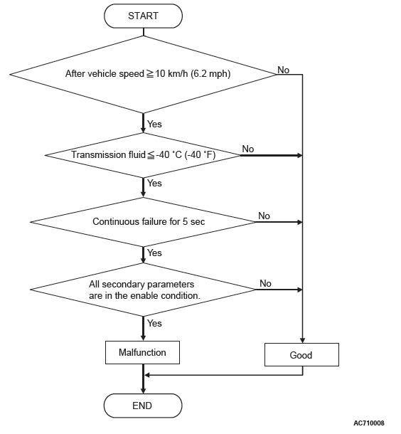
DESCRIPTIONS OF MONITOR METHODS <P0713>
- TCM detects the fluid temperature −40ºC (−40ºF) or less for 5 seconds.
MONITOR EXECUTION <P0713>
- Vehicle speed 10 km/h or more has been detected during 1 drive cycle
MONITOR EXECUTION CONDITIONS (OTHER MONITOR AND SENSOR) <P0713>
Other Monitor (There is no temporary DTC stored in memory for the item monitored below)
- P0741: Abnormality in lockup function
- P0746: Abnormality in hydraulic control system function
- P0841: Abnormality in line pressure sensor function
Sensor (The sensor below is determined to be normal)
- Not applicable
LOGIC FLOW CHARTS (Monitor Sequence) <P0713>
DTC SET CONDITIONS <P0713>
Check Conditions
- After vehicle speed: 10 km/h (6.2 mph) or more.
- Voltage of battery: 9 volts or more.
- Voltage of battery: 16 volts or less.
JUDGMENT CRITERIA
- Value of temperature of transmission fluid: −40ºC (-40ºF) or less. (5 seconds)
OBD-II DRIVE CYCLE PATTERN <P0713>
transmission range: D (Drive the vehicle for 10 seconds or more while the accelerator opening angle is 20% or more)
PROBABLE CAUSES
- Malfunction of the valve body assembly (Faulty transmission fluid temperature sensor)
- Damaged wiring harness and connectors
- Malfunction of TCM
DIAGNOSTIC PROCEDURE
STEP 1. M.U.T.-III data list
Item 5: Transmission fluid temperature sensor signal.
Q: Is the check result normal?
YES : Intermittent malfunction NO : Go to Step 2.
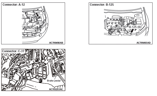
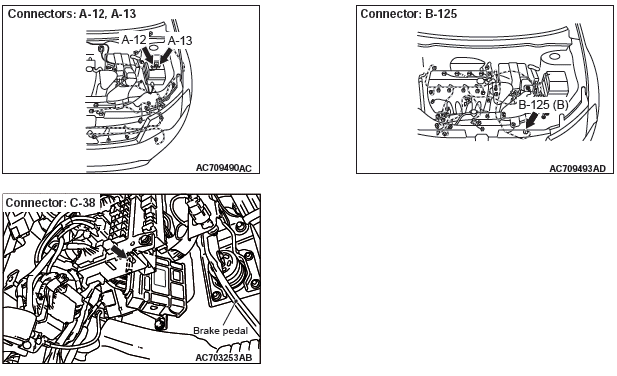
STEP 2. Check the following connector:
- B-125 Transaxle assembly connector
- C-37 TCM connector
- A-12 Intermediate connector
Check the terminals for a contact status problem and internal short circuit.
Q: Is the check result normal?
YES : Go to Step 3.
NO : Repair the defective connector.
STEP 3. Check for open circuit and short to ground in the wiring harness between the CVT assembly connector and the TCM connector
Between B-125 CVT assembly connector (terminal No.17) and C-37 TCM connector (terminal No.50)
Q: Is the check result normal?
YES : Go to Step 4.
NO : Repair the wiring harness.
STEP 4. Check for open circuit in the wiring harness between the CVT assembly connector and the TCM connector
Between B-125 CVT assembly connector (terminal No.19) and C-37 TCM connector (terminal No.48)
Q: Is the check result normal?
YES : Go to Step 5.
NO : Repair the wiring harness.
STEP 5. Transmission fluid temperature sensor check
Q: Is the check result normal?
YES : Go to Step 6.
NO : Replace the valve body assembly.
STEP 6. Symptom recheck after erasing diagnostic trouble code
Q: Is the check result normal?
YES : Intermittent malfunction NO : Replace TCM.
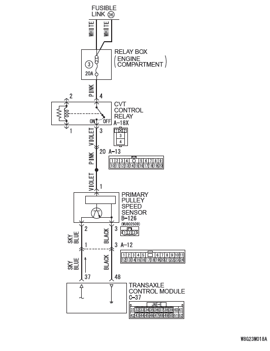
DTC P0715: Malfunction of Primary Pulley Speed Sensor
Primary pulley speed sensor switch system circuit
DIAGNOSTIC FUNCTION
TCM determines that the malfunction is present when the primary pulley speed sensor value changes abruptly or when there is a discrepancy between this sensor and other sensors in sensor reading.
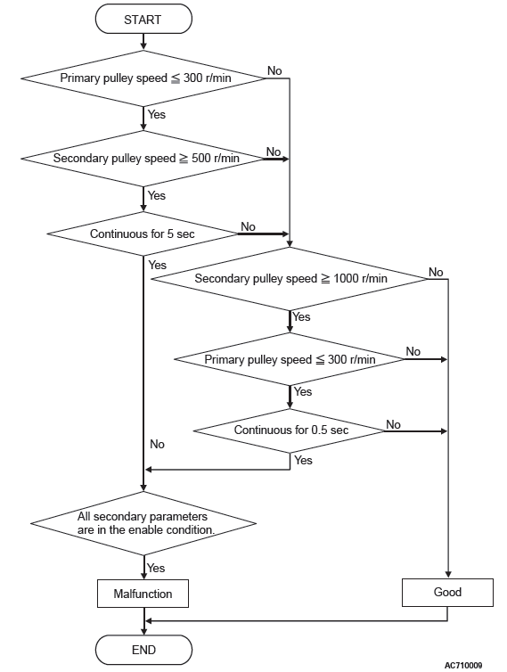
DESCRIPTIONS OF MONITOR METHODS
- The status with the secondary pulley speed of 500 r/min or more and with the primary pulley speed of 150 r/min or less continues for 5 seconds.
- When the primary pulley speed has dropped abruptly from 1,000 r/min or more to 300 r/min or less, and then it keeps 300 r/min or less for 0.5 seconds continuously.
MONITOR EXECUTION
- Transmission range: D
- Throttle valve opening : 1/8 or more
- Engine speed : 450 r/min or more
MONITOR EXECUTION CONDITIONS (OTHER MONITOR AND SENSOR)
Other Monitor (There is no temporary DTC stored in memory for the item monitored below)
- P0712, P0713: Malfunction of the transmission fluid temperature sensor
- P0720: Malfunction of secondary pulley speed sensor
- P0725: Malfunction of engine speed
- P0741: Abnormality in lockup function
- P0746: Abnormality in hydraulic control system function
- P0841: Abnormality in line pressure sensor function
- P0868: Secondary pressure drop
- P1723: Abnormality in speed sensor system function
Sensor (The sensor below is determined to be normal)
- Transmission fluid temperature sensor
- Secondary pulley speed sensor
LOGIC FLOW CHARTS (Monitor Sequence)
DTC SET CONDITIONS
Check Conditions
- Transmission range switch position: D.
- Secondary pulley speed: 500 r/min or more.
- Primary pulley speed at 10 millisecond before: 1,000 r/min or more.
- Throttle position sensor voltage: 1.37 volts or more.
- Engine speed: 450 r/min or more.
- Voltage of battery: 9 volts or more.
- Voltage of battery: 16 volts or less.
JUDGMENT CRITERIA
- Primary pulley speed [secondary pulley speed: 1000 r/min or more]: 300 r/min or less. (5 seconds)
- Primary pulley speed [Primary pulley speed at 10 millisecond before: 1,000 r/min or more]: 300 r/min or less. (0.5 second)
OBD-II DRIVE CYCLE PATTERN
Transmission range: D (Drive the vehicle for 20 seconds or more while the accelerator opening angle is 20% or more)
PROBABLE CAUSES
- Malfunction of primary pulley speed sensor
- Damaged wiring harness and connectors
- Malfunction of TCM
DIAGNOSTIC PROCEDURE
STEP 1. M.U.T.-III data list
Item 1: Primary speed sensor signal.
Q: Is the check result normal?
YES : Intermittent malfunction
NO : Go to Step 2.
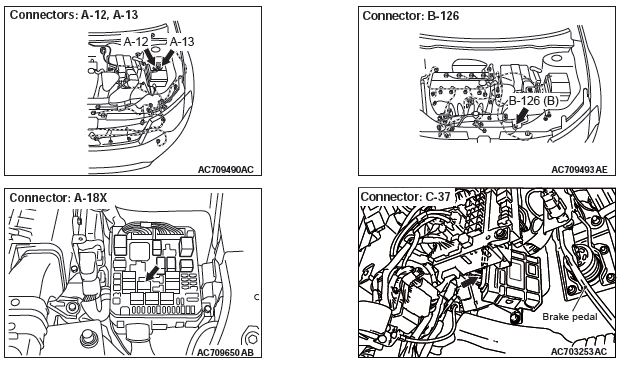
STEP 2. Check the following connector:
- B-126 Primary pulley speed sensor connector
- C-37 TCM connector
- A-12 Intermediate connector
Check the terminals for a contact status problem and internal short circuit.
Q: Is the check result normal?
YES : Go to Step 3.
NO : Repair the defective connector.
STEP 3. Check for open circuit in the wiring harness between the primary pulley speed sensor connector and the TCM connector
Between B-126 primary pulley speed sensor connector (terminal No.3) and C-37 TCM connector (terminal No.48)
Q: Is the check result normal?
YES : Go to Step 4.
NO : Repair the wiring harness.
STEP 4. Check for open circuit and short to ground in wiring harness between the primary pulley speed sensor connector and the TCM connector
Between B-126 primary pulley speed sensor connector (terminal No.2) and C-37 TCM connector (terminal No.37)
Q: Is the check result normal?
YES : Go to Step 5.
NO : Repair the wiring harness.
STEP 5. Check for open circuit in the wiring harness between the CVT control relay and the primary pulley speed sensor connector.
Between A-18X CVT control relay (terminal No.3) and B-126 primary pulley speed sensor connector (terminal No.1)
Q: Is the check result normal?
YES : Go to Step 6.
NO : Repair the wiring harness.
STEP 6. Primary pulley speed sensor check
Visually check the tip of the sensor for foreign materials or damage.
Q: Is the check result normal?
YES : Go to Step 7.
NO : Repair.
STEP 7. Diagnostic trouble code recheck after replacing the primary pulley speed sensor
Q: Is the check result normal?
YES : The procedure is complete.
NO : Replace TCM.
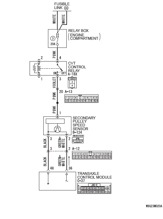
DTC P0720: Malfunction of Secondary Pulley Speed Sensor
Secondary pully speed sensor system circuit
DIAGNOSTIC FUNCTION
TCM determines that the malfunction is present when the secondary pulley speed sensor value changes abruptly or when there is a discrepancy between this sensor and other sensors in sensor reading.
DESCRIPTIONS OF MONITOR METHODS
- The status with the primary pulley speed of 1,000 r/min or more and with the secondary pulley speed of 150 r/min or less continues for 5 seconds.
- When the vehicle speed computed by CVT has dropped abruptly from 10 km/h (6.2 mph) or more to 5 km/h (3.1 mph) or less, and then the computing value keeps 5 km/h (3.1 mph) or less for 0.5 seconds continuously.
MONITOR EXECUTION
- Transmission range: D
- Throttle valve opening : 1/8 or more
MONITOR EXECUTION CONDITIONS (OTHER MONITOR AND SENSOR)
Other Monitor (There is no temporary DTC stored in memory for the item monitored below)
- P0705: Malfunction of transmission range switch
- P0712, P0713: Malfunction of the transmission fluid temperature sensor
- P0715: Malfunction of primary pulley speed sensor
- P0725: Malfunction of engine speed
- P0741: Abnormality in lockup function
- P0746: Abnormality in hydraulic control system function
- P0841: Abnormality in line pressure sensor function
- P0868: Secondary pressure drop
- P1706: Malfunction of throttle signal
- P1723: Abnormality in speed sensor system function
Sensor (The sensor below is determined to be normal)
- Transmission range switch
- Transmission fluid temperature sensor
- Primary pulley speed sensor
- Accelerator pedal position sensor
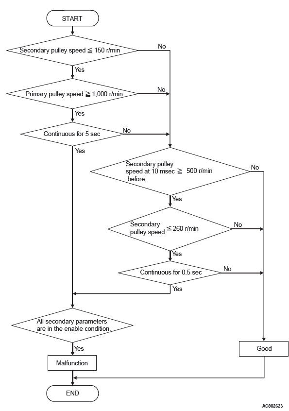
LOGIC FLOW CHARTS (Monitor Sequence)
DTC SET CONDITIONS
Check Conditions
- Transmission range switch position: D.
- Throttle position sensor voltage: 1.37 volts or more.
- Primary pulley speed: 1,000 r/min or more.
- Secondary pulley speed at 10 millisecond before: 500 r/min or more.
- Voltage of battery: 9 volts or more.
- Voltage of battery: 16 volts or less.
JUDGMENT CRITERIA
- Secondary pulley speed [primary pulley speed: 1,000 r/min or more]: 150 r/min or less. (5 seconds)
- Secondary pulley speed [secondary speed at 10 millisecond before: 500 r/min or more]: 260 r/min or less. (0.5 second)
OBD-II DRIVE CYCLE PATTERN
Transmission range: D (Drive the vehicle for 10 seconds or more while the accelerator opening angle is 20% or more)
PROBABLE CAUSES
- Malfunction of secondary pulley speed sensor
- Damaged wiring harness and connectors
- Malfunction of TCM
DIAGNOSTIC PROCEDURE
STEP 1. M.U.T.-III data list
Item 2: Secondary speed sensor signal.
Q: Is the check result normal?
YES : Intermittent malfunction NO : Go to Step 2.
STEP 2. Check the following connector:
- C-37 TCM connector
- B-124 Secondary pulley speed sensor connector
- B-13 Intermediate connector
Check the terminals for a contact status problem and internal short circuit.
Q: Is the check result normal?
YES : Go to Step 3.
NO : Repair the defective connector.
STEP 3. Check for open circuit in the wiring harness between the secondary pulley speed sensor connector and the TCM connector.
Between B-124 secondary pulley speed sensor connector (terminal No.3) and C-37 TCM connector (terminal No.48)
Q: Is the check result normal?
YES : Go to Step 4.
NO : Repair the wiring harness.
STEP 4. Check for open circuit and short to ground in the wiring harness between the secondary pulley speed sensor connector and the TCM connector
Between B-124 secondary pulley speed sensor connector (terminal No.2) and C-37 TCM connector (terminal No.36)
Q: Is the check result normal?
YES : Go to Step 5.
NO : Repair the wiring harness.
STEP 5. Check for open circuit in the wiring harness between the CVT control relay and the secondary pulley speed sensor connector.
Between A-18X CVT control relay (terminal No.3) and B-124 secondary pulley speed sensor connector (terminal No.1)
Q: Is the check result normal?
YES : Go to Step 6.
NO : Repair the wiring harness.
STEP 6. Secondary pulley speed sensor check
Visually check the tip of the sensor for foreign materials or damage.
Q: Is the check result normal?
YES : Go to Step 7.
NO : Repair.
STEP 7. Diagnostic trouble code recheck after replacing the secondary pulley speed sensor
Q: Is the check result normal?
YES : The inspection is complete.
NO : Replace TCM.
DTC P0725: Malfunction of Engine Speed
DIAGNOSTIC FUNCTION
TCM detects malfunction of engine speed received from the ECM by comparing the primary pulley speed with the secondary pulley speed.
DESCRIPTIONS OF MONITOR METHODS
- Primary pulley speed of 1,000 r/min or more and with the engine speed of 450 r/min or less
- When the differences in rotation between the engine and the primary pulley, and between the engine and the secondary pulley are 1,000 r/min or more during direct-coupled operating
- CAN communication error occurs between ECM and TCM.
MONITOR EXECUTION
- Transmission range: D
- Throttle valve opening : 1/8 or more
MONITOR EXECUTION CONDITIONS (OTHER MONITOR AND SENSOR)
Other Monitor (There is no temporary DTC stored in memory for the item monitored below)
- P0705: Malfunction of transmission range switch
- P0715: Malfunction of primary pulley speed sensor
- P0741: Abnormality in lockup function
- P0746: Abnormality in hydraulic control system function
- P0841: Abnormality in line pressure sensor function
- P1706: Malfunction of throttle signal
Sensor (The sensor below is determined to be normal)
- Transmission range switch
- Primary pulley speed sensor
- Accelerator pedal position sensor
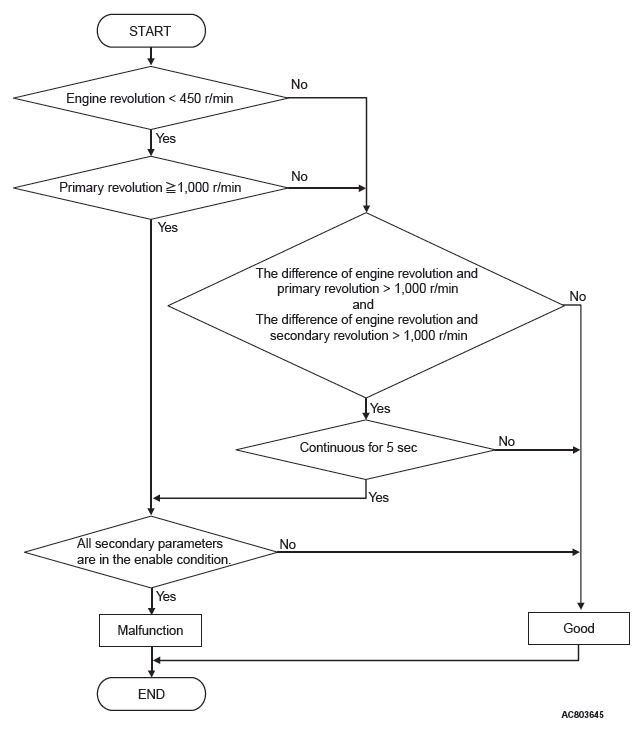
LOGIC FLOW CHARTS (Monitor Sequence)
DTC SET CONDITIONS
Check Conditions
- Transmission range switch position: D.
- Throttle position sensor voltage: 1.37 volts or more.
- Primary pulley speed: 1,000 r/min or more.
- The absolute value of the Primary pulley speed - secondary pulley speed: 1,000 r/min or less.
- Voltage of battery: 9 volts or more.
- Voltage of battery: 16 volts or less.
JUDGMENT CRITERIA
- Engine revolution [primary pulley speed: 1,000 r/min or more]: less than 450 r/min.
- The difference of engine speed and primary speed: more than 1,000 r/min. (5 seconds)
- The difference of engine speed and secondary speed: more than 1,000 r/min. (5 seconds)
OBD-II DRIVE CYCLE PATTERN
Transmission range: D (Drive the vehicle for 10 seconds or more while the accelerator opening angle is 20% or more)
PROBABLE CAUSES
- Malfunction of the CAN bus
- Malfunction of the engine system
- Malfunction of TCM
DIAGNOSTIC PROCEDURE
STEP 1. Using scan tool MB991958, diagnose the CAN bus line.
Use scan tool MB991958 to perform the CAN bus diagnosis.
Q: Is the check result normal?
YES : Go to Step 2.
NO : Go to "CAN Troubleshooting".
STEP 2. Scan tool MB991958 diagnostic trouble code
Check if the engine-related diagnostic trouble code is set.
Q: Is the check result normal?
YES : Go to Step 3.
NO : Go to "Engine Troubleshooting". STEP 3. Symptom recheck after erasing diagnostic trouble code
Q: Is the check result normal?
YES : Intermittent malfunction NO : Replace TCM.
DTC P0740: Malfunction of Lockup Solenoid Valve
Solenoid valve system circuit
DIAGNOSTIC FUNCTION
TCM determines malfunction by detecting the abnormality in the lockup solenoid valve.
DESCRIPTIONS OF MONITOR METHODS
- Specified amount of current is not flown to the lockup solenoid valve because of an open or short circuit.
MONITOR EXECUTION
- Continuous
MONITOR EXECUTION CONDITIONS (OTHER MONITOR AND SENSOR)
Other Monitor (There is no temporary DTC stored in memory for the item monitored below)
- P0741: Abnormality in lockup function
- P0746: Abnormality in hydraulic control system function
- P0841: Abnormality in line pressure sensor function
Sensor (The sensor below is determined to be normal)
- Not applicable
LOGIC FLOW CHARTS (Monitor Sequence)
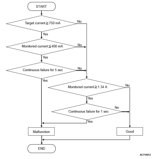
DTC SET CONDITIONS
JUDGMENT CRITERIA
- Monitored current [target current: 750 mA or more]: 400 mA or less. (5 seconds)
- Monitored current: 1.34 A or more. (1 second)
OBD-II DRIVE CYCLE PATTERN
Ignition switch : ON (start the engine and keep it for 10 seconds or more)
PROBABLE CAUSES
- Malfunction of valve body assembly (Faulty lockup solenoid valve)
- Damaged wiring harness and connectors
- Malfunction of TCM
DIAGNOSTIC PROCEDURE
STEP 1. M.U.T.-III data list
- Item 31: LU solenoid output current
- Item 30: LU solenoid monitor current
OK: Check if the output current and monitoring current differ largely.
Q: Is the check result normal?
YES : Intermittent malfunction
NO : Go to Step 2.
STEP 2. Check the following connector:
- C-38 TCM connector
- B-125 CVT assembly connector
Check the terminals for a contact status problem and internal short circuit.
Q: Is the check result normal?
YES : Go to Step 3.
NO : Repair the defective connector.
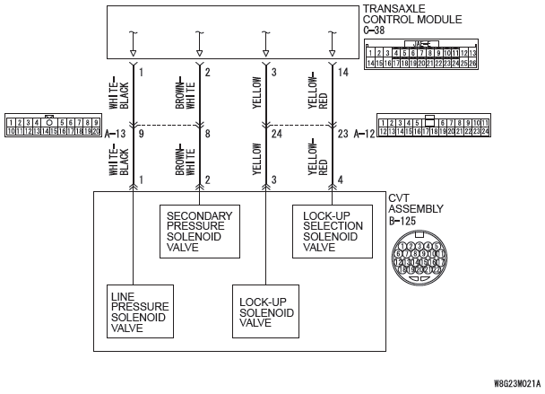
STEP 3. Check for open circuit and short to ground in the wiring harness between the TCM connector and the CVT assembly connector.
Between C-38 TCM connector (terminal No.3) and B-125 CVT assembly connector (terminal No.3)
Q: Is the check result normal?
YES : Go to Step 4.
NO : Repair the wiring harness.
STEP 4. Lockup solenoid valve single unit check
Q: Is the check result normal?
YES : Go to Step 5.
NO : Replace the valve body assembly.
STEP 5. Symptom recheck after erasing diagnostic trouble code
Q: Is the check result normal?
YES : Intermittent malfunction NO : Replace TCM.
DTC P0741: Abnormality in Lock-up Function
DIAGNOSTIC FUNCTION
Abnormality is detected by the TCM when the torque converter slip speed is high during lockup control.
DESCRIPTIONS OF MONITOR METHODS
- The status with the high torque converter slip speed continues for 30 seconds during lockup control [Primary pulley speed and engine speed are normal, and lockup differential pressure is 0.2 MPa (29 psi) or more].
MONITOR EXECUTION
- Transmission range: D
- Throttle valve opening : 1/8 or more
- Engine speed : 450 r/min or more
- CVT fluid temperature : from 20 to 180ºC (68~356ºF)
MONITOR EXECUTION CONDITIONS (OTHER MONITOR AND SENSOR)
Other Monitor (There is no temporary DTC stored in memory for the item monitored below)
- P0746: Abnormality in hydraulic control system function
- P0841: Abnormality in line pressure sensor function
- P0868: Secondary pressure drop
Sensor (The sensor below is determined to be normal)
- Not applicable
LOGIC FLOW CHARTS (Monitor Sequence)
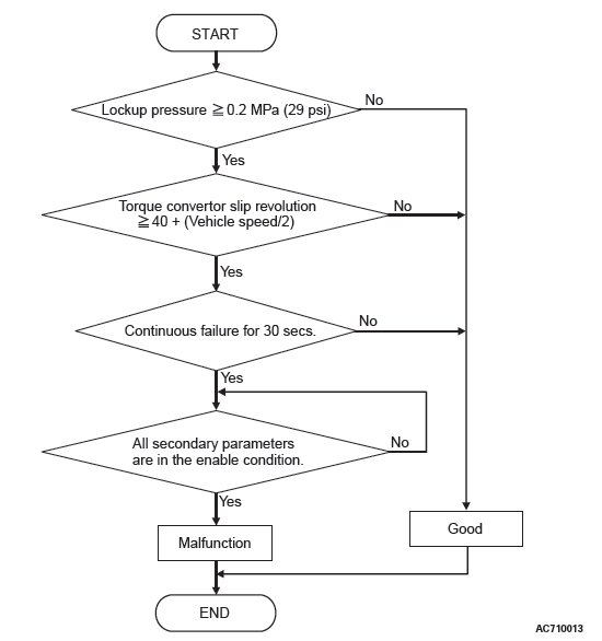
DTC SET CONDITIONS
Check Conditions
- Transmission range switch position: D.
- Throttle position sensor voltage: 1.37 volts or more.
- Engine speed: 450 r/min or more.
- Transmission fluid temperature: 20ºC (68ºF) or more.
- Transmission fluid temperature: 180ºC (356ºF) or less.
- Voltage of battery: 9 volts or more.
- Voltage of battery: 16 volts or less.
JUDGMENT CRITERIA
- Lock-up pressure: 0.2 MPa (29 psi) or more. (30 seconds)
- Torque converter slip revolution: 40+(vehicle speed/2) or more. (30 seconds)
OBD-II DRIVE CYCLE PATTERN
Transmission range: D (Drive the vehicle for 30 seconds or more while the accelerator opening angle is 20% or more)
PROBABLE CAUSES
- Abnormal line pressure
- Malfunction of TCM
DIAGNOSTIC PROCEDURE
STEP 1. Check other diagnostic trouble codes.
Q: Are other diagnostic trouble codes set?
YES : Carry out the appropriate troubleshooting.
NO : Go to Step 2.
STEP 2. M.U.T.-III data list
- Item 7: Primary speed
- Item 9: Engine revolution
OK: No considerable difference is observed between the primary pulley speed and the engine speed.
Q: Is the check result normal?
YES : Intermittent malfunction
NO : Go to Step 3.
STEP 3. Line Pressure Check
Carry out "hydraulic test".
Q: Is the check result normal?
YES : Go to Step 4.
NO : Repair according to the hydraulic pressure test diagnosis table.
STEP 4. Symptom recheck after erasing diagnostic trouble code
Q: Is the check result normal?
YES : Intermittent malfunction
NO : Replace TCM.
DTC P0745: Malfunction of Line Pressure Solenoid Valve
DIAGNOSTIC FUNCTION
TCM determines malfunction by detecting the abnormality in the line pressure solenoid valve.
DESCRIPTIONS OF MONITOR METHODS
- Specified amount of current is not flown to the line pressure solenoid valve because of an open or short circuit.
MONITOR EXECUTION
- Continuous
MONITOR EXECUTION CONDITIONS (OTHER MONITOR AND SENSOR)
Other Monitor (There is no temporary DTC stored in memory for the item monitored below)
- P0741: Abnormality in lockup function
- P0746: Abnormality in hydraulic control system function
- P0841: Abnormality in line pressure sensor function
- P0868: Secondary pressure drop
Sensor (The sensor below is determined to be normal)
- Not applicable
LOGIC FLOW CHARTS (Monitor Sequence)
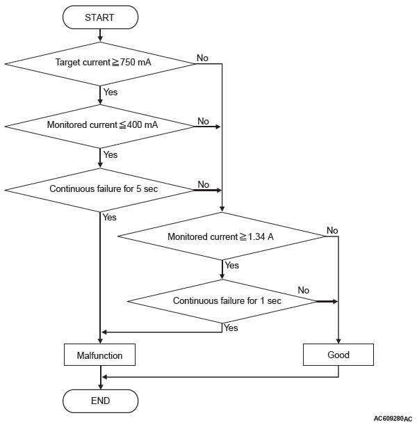
DTC SET CONDITIONS
JUDGMENT CRITERIA
- Monitored current [target current: 750 mA or more]: 400 mA or less. (5 seconds)
- Monitored current: 1.34 A or more. (1 second)
OBD-II DRIVE CYCLE PATTERN
Ignition switch : ON (start the engine and keep it for 10 seconds or more)
PROBABLE CAUSES
- Malfunction of valve body assembly (Faulty line pressure solenoid valve)
- Damaged wiring harness and connectors
- Malfunction of TCM
DIAGNOSTIC PROCEDURE
STEP 1. M.U.T.-III data list
- Item 33: Line pressure SOL. output current
- Item 32: Line pressure SOL. monitor current
OK: Check if the output current and monitoring current differ largely.
Q: Is the check result normal?
YES : Intermittent malfunction
NO : Go to Step 2.
STEP 2. Check the following connector:
- C-38 TCM connector
- B-125 CVT assembly connector
Check the terminals for a contact status problem and internal short circuit.
Q: Is the check result normal?
YES : Go to Step 3.
NO : Repair the defective connector.
STEP 3. Check for open circuit and short to ground in the wiring harness between the TCM connector and the CVT assembly connector.
Between C-38 TCM connector (terminal No.1) and B-125 CVT assembly connector (terminal No.1)
Q: Is the check result normal?
YES : Go to Step 4.
NO : Repair the wiring harness.
STEP 4. Line pressure solenoid valve single unit check
Q: Is the check result normal?
YES : Go to Step 5.
NO : Replace the valve body assembly.
STEP 5. Symptom recheck after erasing diagnostic trouble code
Q: Is the check result normal?
YES : Intermittent malfunction
NO : Replace TCM.
READ NEXT:
 DTC P0746, P0776, P0778, P0815, P0816, P0826, P0840, P0841, P0868,
P0882, P0883
DTC P0746, P0776, P0778, P0815, P0816, P0826, P0840, P0841, P0868,
P0882, P0883
DTC P0746: Abnormality in Hydraulic Control System Function
DIAGNOSTIC FUNCTION
TCM determines that the malfunction is present
when pulley ratio becomes higher (pulley ratio range:
2.349 to 0.394).
DE
DTC P1637, P1706, P1710, P1723, P1740, P1745, P1773, P1777, P1778,
P1902, U0001, U0100, U0121, U0141
DTC P1637: Malfunction of Memory Backup
Memory backup system circuit
DIAGNOSTIC FUNCTION
TCM checks the consistency between EEPROM and
the backup memory.
DESCRIPTIONS OF MONITOR METHODS
When the ig
Symptom Procedures
Inspection Procedure 1: TCM cannot communication with scan tool.
TCM POWER SUPPLY CIRCUIT
SYMPTOMS
TCM cannot be turned ON.
PROBABLE CAUSES
Damaged wiring harness and connectors
Malfunction of TCM
SEE MORE:
Symptom Procedures (Inspection Procedure 1-6)
INSPECTION PROCEDURE 1: The windshield wipers do not work at all.
Windshield Wiper Power Supply Circuit
CIRCUIT OPERATION
The windshield wiper and washer switch sends a
signal through the column-ECU (incorporated in
the column switch) to the ETACS-ECU. If the column-
ECU sends a windshield wi
General Information
CONSTRUCTION DIAGRAM
<Except color liquid crystal display>
<Color liquid crystal display>
SERVICE SPECIFICATIONS
SPECIAL TOOLS
COMBINATION METERS DIAGNOSTIC
STANDARD FLOW OF DIAGNOSTIC
TROUBLESHOOTING
Refer to GROUP 00, Contents of troubleshooting.
DIAGNOSTIC FUNCTION
HOW TO CONNE
