Mitsubishi Outlander: DTC P1637, P1706, P1710, P1723, P1740, P1745, P1773, P1777, P1778, P1902, U0001, U0100, U0121, U0141
DTC P1637: Malfunction of Memory Backup
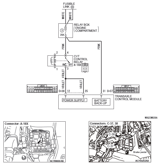
Memory backup system circuit
DIAGNOSTIC FUNCTION
TCM checks the consistency between EEPROM and the backup memory.
DESCRIPTIONS OF MONITOR METHODS
- When the ignition switch is turned to the "ON" position, TCM determines that the writing to the EEPROM area had failed last time the ignition switch was turned to the "LOCK" (OFF) position.
MONITOR EXECUTION
- Continuous
MONITOR EXECUTION CONDITIONS (OTHER MONITOR AND SENSOR)
Other Monitor (There is no temporary DTC stored in memory for the item monitored below)
- Not applicable
Sensor (The sensor below is determined to be normal)
- Not applicable
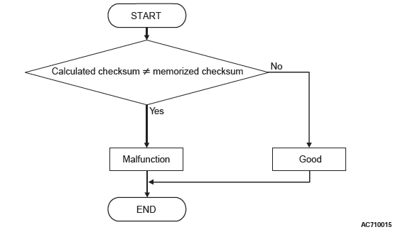
LOGIC FLOW CHARTS (Monitor Sequence)
DTC SET CONDITIONS
JUDGMENT CRITERIA
- Calculated checksum is not same as memorized checksum.
OBD-II DRIVE CYCLE PATTERN
Ignition switch : ON (start the engine and keep it for 10 seconds or more)
PROBABLE CAUSES
- Damaged wiring harness and connectors
- Malfunction of TCM (Faulty EEPROM)
DIAGNOSTIC PROCEDURE
STEP 1. Check if diagnostic trouble code P1637 is erased by turning the ignition switch from the "LOCK" (OFF) position to the "ON" position.
Q: Is the check result normal?
YES : This diagnostic trouble code will be set by disconnecting the battery. If the diagnostic trouble code is not erased by turning the ignition switch to the "ON" position, it is judged to be normal.
NO : Go to Step 2.
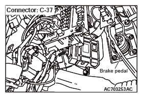
STEP 2. Check for open circuit in power supply wiring harness
- Between relay box and C-37 TCM backup power supply connector (terminal No.31)
- Between relay box and A-18X CVT control relay (terminal No.4)
Q: Is the check result normal?
YES : Go to Step 3.
NO : Repair the wiring harness.
STEP 3. Symptom recheck after erasing diagnostic trouble code
Q: Is the check result normal?
YES : Intermittent malfunction
NO : Replace TCM.
DTC P1706: Malfunction of Throttle Signal
DIAGNOSTIC FUNCTION
TCM detects the abnormality in the throttle position signal sent from the ECM.
DESCRIPTIONS OF MONITOR METHODS
- The difference between the throttle position signal received from the ECM and the corresponding turnover value is 1.37 V or more, and this status continues for 1 second.
MONITOR EXECUTION
- Transmission range: D
MONITOR EXECUTION CONDITIONS (OTHER MONITOR AND SENSOR)
Other Monitor (There is no temporary DTC stored in memory for the item monitored below)
- P0705: Malfunction of transmission range switch
- P0715: Malfunction of primary pulley speed sensor
- P0720: Malfunction of secondary pulley speed sensor
- P0725: Malfunction of engine speed
- P0741: Abnormality in lockup function
- P0746: Abnormality in hydraulic control system function
- P0841: Abnormality in line pressure sensor function
Sensor (The sensor below is determined to be normal)
- Transmission range switch
- Primary pulley speed sensor
- Secondary pulley speed sensor
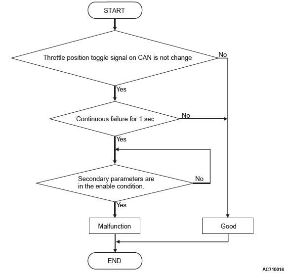
LOGIC FLOW CHARTS (Monitor Sequence)
DTC SET CONDITIONS
Check Conditions
- Transmission range switch position: D.
- Voltage of battery: 9 volts or more.
- Voltage of battery: 16 volts or less.
JUDGMENT CRITERIA
- Throttle position toggle signal on CAN: not change. (1 second)
OBD-II DRIVE CYCLE PATTERN
Ignition switch : ON (start the engine and keep it for 10 seconds or more)
PROBABLE CAUSES
- Malfunction of the CAN bus
- Malfunction of engine system
- Malfunction of TCM
DIAGNOSTIC PROCEDURE
STEP 1. Using scan tool MB991958, diagnose the CAN bus line.
Use scan tool MB991958 to perform the CAN bus diagnosis.
Q: Is the check result normal?
YES : Go to Step 2.
NO : Repair the CAN bus lines.
STEP 2. Scan tool MB991958 diagnostic trouble code
Check if the engine-related diagnostic trouble code is set.
Q: Is diagnostic trouble code set?
YES : Diagnose the engine control system.
NO : Go to Step 3.
STEP 3. Symptom recheck after erasing diagnostic trouble code
Q: Is the check result normal?
YES : Intermittent malfunction
NO : Replace TCM.
DTC P1710: Malfunction of Vehicle Speed Signal
DIAGNOSTIC FUNCTION
TCM conducts fault detection by detecting the rapid change in the estimated vehicle speed signal received from the ABC-ECU.
JUDGMENT CRITERIA
- Difference between the estimated vehicle speed and the one measured before 0.1 second is 29 km/h (18.0 mph) or more.
- The status with the vehicle speed of 10 km/h (6.2 mph) or more and with the estimated vehicle speed of 2 km/h (1.2 mph) or less continues for 20 seconds.
PROBABLE CAUSES
- Malfunction of the CAN bus
- Malfunction of TCM
DIAGNOSTIC PROCEDURE
STEP 1. Troubleshoot the CAN system if diagnosis code U0121 is set.
Q: Is the diagnosis code U0121 set?
YES : Diagnose the CAN system.
NO : Go to Step 2.
STEP 2. M.U.T.-III data list
- Item 21: Vehicle speed (inference)
- Item 22: Real vehicle speed
OK: Vehicle speed signal and vehicle speed do not differ greatly.
Q: Is the check result normal?
YES : Intermittent malfunction
NO : Go to Step 3.
STEP 3. Check ABS-related diagnosis codes.
Q: Is the ABS-related diagnosis code set?
YES : Carry out the appropriate troubleshooting.
NO : Go to Step 4.
STEP 4. Symptom recheck after erasing diagnosis code
Q: Is the check result normal?
YES : Intermittent malfunction
NO : Replace TCM.
DTC P1723: Abnormality in Speed Sensor System Function
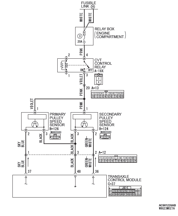
Speed sensor system circuit
DIAGNOSTIC FUNCTION
TCM detects the abnormal wave pattern of the speed sensor signal.
DESCRIPTIONS OF MONITOR METHODS
- Rotational fluctuation of primary pulley is large (for 1 second).
- Rotational fluctuation of secondary pulley is large (for 1 second).
MONITOR EXECUTION
- Continuous
MONITOR EXECUTION CONDITIONS (OTHER MONITOR AND SENSOR)
Other Monitor (There is no temporary DTC stored in memory for the item monitored below)
- P0741: Abnormality in lockup function
- P0746: Abnormality in hydraulic control system function
- P0841: Abnormality in line pressure sensor function
- P0868: Secondary pressure drop
Sensor (The sensor below is determined to be normal)
- Not applicable
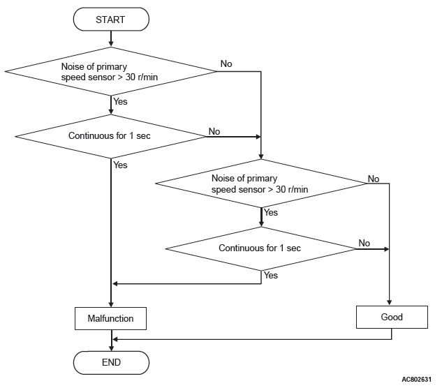
LOGIC FLOW CHARTS (Monitor Sequence)
DTC SET CONDITIONS
Check Conditions
- Voltage of battery: 9 volts or more.
- Voltage of battery: 16 volts or less.
JUDGMENT CRITERIA
- Noise of primary pulley or primary pulley speed sensor signal: more than 30 r/min. (1 second)
- Noise of primary pulley or secondary pulley speed sensor signal: more than 30 r/min. (1 second)
OBD-II DRIVE CYCLE PATTERN
Ignition switch : ON (start the engine and keep it for 10 seconds or more)
PROBABLE CAUSES
- Malfunction of primary pulley speed sensor
- Malfunction of secondary pulley speed sensor
- Malfunction of TCM
DIAGNOSTIC PROCEDURE
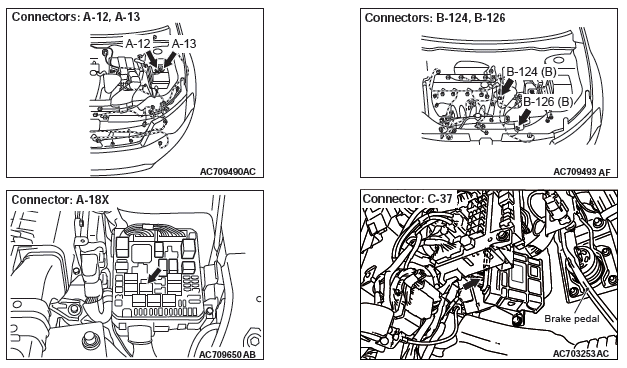
STEP 1. Check the following connector:
- C-37 TCM connector
- B-126 Primary pulley speed sensor connector
- B-124 Secondary pulley speed sensor connector
Check for the connection with terminals.
Q: Is the check result normal?
YES : Go to Step 2.
NO : Repair the defective connector.
STEP 2. Use an oscilloscope to measure the wave patterns of the primary pulley speed sensor and secondary pulley speed sensor.
Q: Is the check result normal?
YES : Go to Step 3.
NO : Replace the primary pulley speed sensor or secondary pulley speed sensor.
STEP 3. Symptom recheck after erasing diagnostic trouble code
Q: Is the check result normal?
YES : Intermittent malfunction
NO : Replace TCM.
DTC P1740: Malfunction of Lockup/Select Switching Solenoid Valve
DIAGNOSTIC FUNCTION
TCM detects abnormal operation of the lockup/select switching solenoid valve.
DESCRIPTIONS OF MONITOR METHODS
- Specified amount of current is not flown to the lockup/select switching solenoid valve because of an open or short circuit.
MONITOR EXECUTION
- Continuous
MONITOR EXECUTION CONDITIONS (OTHER MONITOR AND SENSOR)
Other Monitor (There is no temporary DTC stored in memory for the item monitored below)
- P0741: Abnormality in lockup function
- P0746: Abnormality in hydraulic control system function
- P0841: Abnormality in line pressure sensor function
Sensor (The sensor below is determined to be normal)
- Not applicable
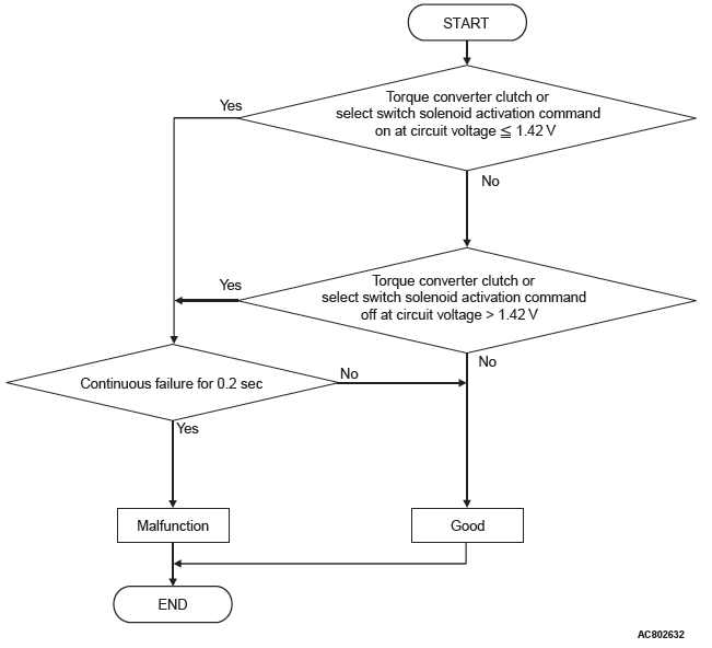
LOGIC FLOW CHARTS (Monitor Sequence)
DTC SET CONDITIONS
Judgment Criteria
- Lockup/select switching solenoid valve activation command (ON voltage): 1.42 volts or less (0.2 second)
- Lockup/select switching solenoid valve activation command (OFF voltage): more than 1.42 volts (0.2 second)
OBD-II DRIVE CYCLE PATTERN
Ignition switch : ON (start the engine and keep it for 10 seconds or more)
PROBABLE CAUSES
- Malfunction of valve body assembly (Faulty lockup/select switching solenoid valve)
- Damaged wiring harness and connectors
- Malfunction of TCM
PROBABLE CAUSES
- Malfunction of valve body assembly (Faulty lockup/select switching solenoid valve)
- Damaged wiring harness and connectors
- Malfunction of TCM
DIAGNOSTIC PROCEDURE
STEP 1. M.U.T.-III data list
- Item 36: LU/SEL changeover SOL. output
- Item 37: LU/SEL changeover SOL. monitor
OK: Check that the output and monitor do not differ greatly.
Q: Is the check result normal?
YES : Intermittent malfunction
NO : Go to Step 2.
STEP 2. Check the following connector:
- B-125 CVT assembly connector
- C-38 TCM connector
- A-12 Intermediate connector
Check the terminals for a contact status problem and internal short circuit.
Q: Is the check result normal?
YES : Go to Step 3.
NO : Repair the defective connector.
STEP 3. Check for open circuit and short to ground in the wiring harness between the TCM connector and the CVT assembly connector.
Between C-38 TCM connector (terminal No.14) and B-125 CVT assembly connector (terminal No.4)
Q: Is the check result normal?
YES : Go to Step 4.
NO : Repair the wiring harness.
STEP 4. Lockup/select switching solenoid valve single unit check
Q: Is the check result normal?
YES : Go to Step 5.
NO : Replace the valve body assembly.
STEP 5. Symptom recheck after erasing diagnostic trouble code
Q: Is the check result normal?
YES : Intermittent malfunction
NO : Replace TCM.
DTC P1745: Monitoring of Percentage Change in Pulley Ratio
DIAGNOSTIC FUNCTION
TCM conducts fault detection by monitoring the internal calculated value.
JUDGEMENT CRITERIA
Percentage change in pulley ratio is larger than the standard value.
PROBABLE CAUSES
- Malfunction of TCM
DIAGNOSTIC PROCEDURE
STEP 1. Symptom recheck after erasing diagnosis code
Q: Is the check result normal?
YES : Intermittent malfunction
NO : Replace TCM.
DTC P1773: Malfunction of ABS
DIAGNOSTIC FUNCTION
TCM detects the ABS abnormality.
DESCRIPTIONS OF MONITOR METHODS
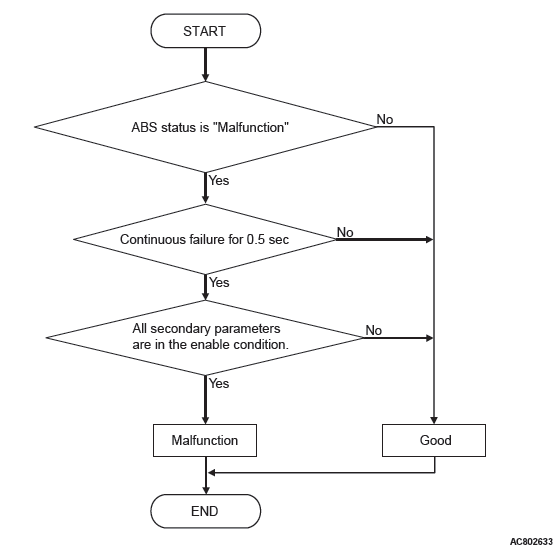
- When the ABS error signal reception continues for 0.5 seconds.
MONITOR EXECUTION
- When 1.05 seconds have elapsed after TCM started (not during M.U.T.-III communication)
MONITOR EXECUTION CONDITIONS (OTHER MONITOR AND SENSOR)
Other Monitor (There is no temporary DTC stored in memory for the item monitored below)
- Not applicable
Sensor (The sensor below is determined to be normal)
- Not applicable
LOGIC FLOW CHARTS (Monitor Sequence)
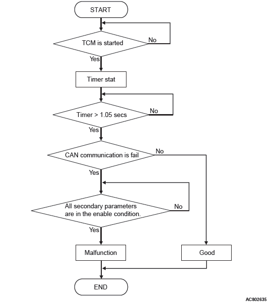
DTC SET CONDITIONS
Check Conditions
- Time after TCM start: more than 1.05 seconds.
Judgment Criteria
- ABS status: malfunction
OBD-II DRIVE CYCLE PATTERN
Ignition switch : ON (start the engine and keep it for 10 seconds or more, not during M.U.T.-III communication)
PROBABLE CAUSES
- Malfunction of the ABS system
- Malfunction of TCM
DIAGNOSTIC PROCEDURE
STEP 1. ABS system DTC check
Q: Is the ABS system DTC set?
YES : Carry out the troubleshooting for ABS.
NO : Go to Step 2.
STEP 2. Symptom recheck after erasing diagnosis code
Q: Is the check result normal?
YES : Intermittent malfunction
NO : Replace TCM.
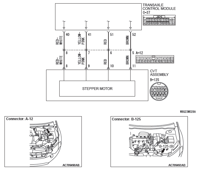
DTC P1777: Malfunction of Stepper Motor
Stepper motor system circuit
DIAGNOSTIC FUNCTION
TCM conducts fault detection by monitoring the voltage of each coil for stepper motors.
DESCRIPTIONS OF MONITOR METHODS
- The specified voltage is not applied to each coil for stepper motors for 0.2 second because of an open or short circuit.
MONITOR EXECUTION
- Continuous
MONITOR EXECUTION CONDITIONS (OTHER MONITOR AND SENSOR)
Other Monitor (There is no temporary DTC stored in memory for the item monitored below)
- P0741: Abnormality in lockup function
- P0746: Abnormality in hydraulic control system function
- P0841: Abnormality in line pressure sensor function
- P0868: Secondary pressure drop
Sensor (The sensor below is determined to be normal)
- Not applicable
LOGIC FLOW CHARTS (Monitor Sequence)
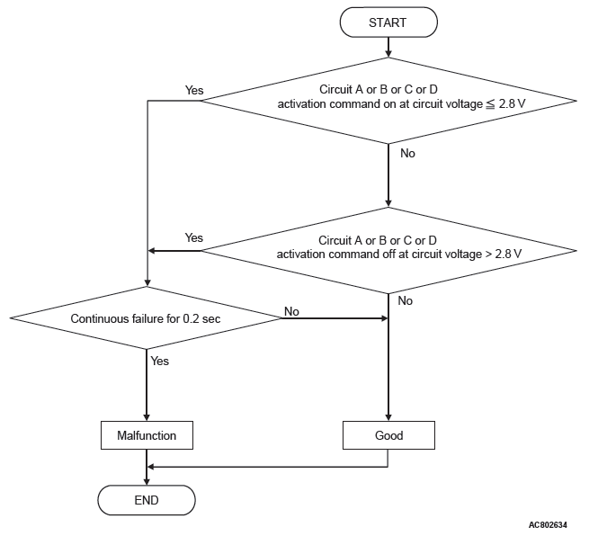
DTC SET CONDITIONS
JUDGMENT CRITERIA
- Stepping motor activation command (ON voltage): 2.8 volts or less. (0.2 second)
- Stepping motor activation command (OFF voltage): More than 2.8 volts. (0.2 second)
OBD-II DRIVE CYCLE PATTERN
Ignition switch : ON (start the engine and keep it for 10 seconds or more)
PROBABLE CAUSES
- Malfunction of valve body assembly (Faulty stepper motor)
- Damaged wiring harness and connectors
- Malfunction of TCM
DIAGNOSTIC PROCEDURE
STEP 1. Check the following connector:
- B-125 CVT assembly connector
- C-37 TCM connector
Check the terminals for a contact status problem and internal short circuit.
Q: Is the check result normal?
YES : Go to Step 2.
NO : Repair the defective connector.
STEP 2. Check for open circuit and short to ground in the wiring harness between the TCM connector and the stepper motor.
- Between TCM connector (terminal No.40) and body ground
- Between TCM connector (terminal No.41) and body ground
- Between TCM connector (terminal No.51) and body ground
- Between TCM connector (terminal No.52) and body ground
OK: Resistance value is approximately 15 Ω.
Q: Is the check result normal?
YES : Go to Step 4.
NO : Go to Step 3.
STEP 3. Check for open circuit and short to ground in the wiring harness between TCM and the stepper motor
- Between C-37 TCM connector (terminal No.40) and B-125 CVT assembly connector (terminal No.8)
- Between C-37 TCM connector (terminal No.41) and B-125 CVT assembly connector (terminal No.9)
- Between C-37 TCM connector (terminal No.51) and B-125 CVT assembly connector (terminal No.10)
- Between C-37 TCM connector (terminal No.52) and B-125 CVT assembly connector (terminal No.11)
Check that there is no continuity in both sides of the connectors and that no short circuit is present between the connectors and the body ground.
Q: Is the check result normal?
YES : Replace the valve body assembly.
NO : Repair the wiring harness.
STEP 4. Symptom recheck after erasing diagnostic trouble code
Q: Is the check result normal?
YES : Intermittent malfunction
NO : Replace TCM.
DTC P1778: Abnormality In Stepper Motor Function
DIAGNOSTIC FUNCTION
TCM conducts the fault detection of the stepper motor by comparing the target value of the primary pulley speed with the actual value. (Target value: Actual secondary pulley speed multiplied by pulley ratio corresponding to stepper motor position) (Actual measurement value: Actual primary pulley speed)
JUDGEMENT CRITERIA
The difference between the target value of the primary pulley speed and the actual measurement value is greater than the standard value, the difference between the target pulley ratio and the actual pulley ratio is 0.3 or greater, and this status continues for 5 seconds.
PROBABLE CAUSES
- Malfunction of TCM
- Malfunction of valve body assembly (Faulty stepper motor)
DIAGNOSTIC PROCEDURE
STEP 1. Check other diagnosis codes.
Q: Are other diagnosis codes set?
YES : Carry out the appropriate troubleshooting.
NO : Go to Step 2.
STEP 2. Symptom recheck after erasing diagnosis code
Q: Is the check result normal?
YES : Intermittent malfunction
NO : Replace the TCM, and then go to Step 3.
STEP 3. Retest the system.
Q: Is the check result normal?
YES : The inspection is complete.
NO : Replace the valve body assembly.
DTC P1902: Malfunction of Engine System
DIAGNOSTIC FUNCTION
- When the ECM detects the malfunction of the ETV system, the ECM enters the limp-home control mode (throttle valve angle: approximately 20%).
- TCM begins controlling the following items: lockup inhibition, increase of secondary pressure, fixing of pulley ratio line.
JUDGEMENT CRITERIA
TCM receives the limp-home signal from ECM via CAN.
PROBABLE CAUSES
- Malfunction of the engine system (ETV)
DIAGNOSIS PROCEDURE
STEP 1. Check the engine-related diagnosis code.
Q: Is the engine-related diagnosis code set?
YES : Carry out the appropriate troubleshooting.
NO : Go to Step 2.
STEP 2. Symptom recheck after erasing diagnosis code
Q: Is the check result normal?
YES : Intermittent malfunction
NO : Replace the TCM.
DTC U0001: Malfunction of CAN Communication Circuit
DIAGNOSTIC FUNCTION
TCM conducts bus-off detection.
DESCRIPTIONS OF MONITOR METHODS
- TCM cannot receive the periodic communication data.
MONITOR EXECUTION
- When 1.05 seconds have elapsed after TCM started
MONITOR EXECUTION CONDITIONS (OTHER MONITOR AND SENSOR)
Other Monitor (There is no temporary DTC stored in memory for the item monitored below)
- P0703: Malfunction of stoplight switch
- P0705: Malfunction of transmission range switch
- P0715: Malfunction of primary pulley speed sensor
- P0720: Malfunction of secondary pulley speed sensor
- P0725: Malfunction of engine speed
- P0741: Abnormality in lockup function
- P0746: Abnormality in hydraulic control system function
- P0841: Abnormality in line pressure sensor function
- P0868: Secondary pressure drop
- P1706: Malfunction of throttle signal
- P1773: Malfunction of ABS
- U0100: CAN time-out error (Engine)
Sensor (The sensor below is determined to be normal)
- Stoplight switch
- Transmission range switch
- Primary pulley speed sensor
- Secondary pulley speed sensor
LOGIC FLOW CHARTS (Monitor Sequence)
DTC SET CONDITIONS
Check Conditions
- Time after TCM start: more than 1.05 seconds.
- Voltage of battery: 9 volts or more
- Voltage of battery: 16 volts or less
Judgment Criteria
- CAN communication: fail
OBD-II DRIVE CYCLE PATTERN
Ignition switch : ON (start the engine and keep it for 10 seconds or more)
PROBABLE CAUSES
- Malfunction of the CAN bus
DIAGNOSTIC PROCEDURE
STEP 1. M.U.T.-III CAN bus diagnostics
Use M.U.T.-III to perform the CAN bus diagnosis.
Q: Is the check result normal?
YES : Intermittent malfunction
NO : Repair the CAN bus lines (Refer to GROUP 54C − Troubleshooting, Diagnosis Code Chart).
DTC U0100: CAN Time-out Error (Engine)
DIAGNOSTIC FUNCTION
TCM receives periodic communication data from the ECM via CAN bus lines.
JUDGMENT CRITERIA
TCM cannot receive the periodic communication data from the ECM.
DESCRIPTIONS OF MONITOR METHODS
- TCM cannot receive the periodic communication data from the ECM.
MONITOR EXECUTION
- When 1.05 seconds have elapsed after TCM started
MONITOR EXECUTION CONDITIONS (OTHER MONITOR AND SENSOR)
Other Monitor (There is no temporary DTC stored in memory for the item monitored below)
- P0725: Malfunction of engine speed
- P0868: Secondary pressure drop
Sensor (The sensor below is determined to be normal)
- Not applicable
LOGIC FLOW CHARTS (Monitor Sequence)
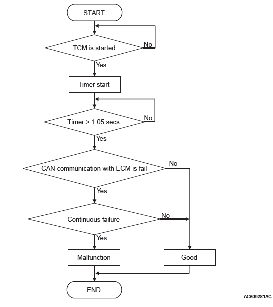
DTC SET CONDITIONS
Check Conditions
- Time after TCM start: more than 1.05 seconds.
- Voltage of battery: 9 volts or more
- Voltage of battery: 16 volts or less
JUDGMENT CRITERIA
- CAN communication with ECM: fail. (500 millisecond)
OBD-II DRIVE CYCLE PATTERN
Ignition switch : ON (start the engine and keep it for 10 seconds or more)
PROBABLE CAUSES
- Malfunction of the CAN bus
- Engine ECU malfunction
- Malfunction of TCM
DIAGNOSTIC PROCEDURE
STEP 1. Using scan tool MB991958, diagnose the CAN bus line.
Use scan tool MB991958 to perform the CAN bus diagnosis.
Q: Is the check result normal?
YES : Go to Step 2.
NO : Repair the CAN bus lines.
STEP 2. Scan tool MB991958 diagnostic trouble code
Check if the engine-related diagnostic trouble code is set.
Q: Is the engine-related diagnostic trouble code set?
YES : Carry out the appropriate troubleshooting.
NO : Go to Step 3.
STEP 3. Symptom recheck after erasing diagnostic trouble code
Q: Is the check result normal?
YES : Intermittent malfunction
NO : Replace TCM.
DTC U0121: CAN Time-out Error (ABS)
DIAGNOSTIC FUNCTION
TCM determines that malfunction is present if the periodic communication data sent from the ABS-ECU via CAN bus lines is abnormal.
JUDGMENT CRITERIA
TCM cannot receive the periodic communication data from ABS-ECU.
PROBABLE CAUSES
- Malfunction of the CAN bus
- ABS-ECU malfunction
- Malfunction of TCM
DIAGNOSTIC PROCEDURE
STEP 1. Using scan tool MB991958, diagnose the CAN bus line.
Use scan tool MB991958 to perform the CAN bus diagnosis.
Q: Is the check result normal?
YES : Go to Step 2.
NO : Repair the CAN bus lines (Refer to GROUP 54C − Troubleshooting, Diagnostic Trouble Code Chart).
STEP 2. Scan tool MB991958 diagnostic trouble code
Check if the ABS-related diagnostic trouble code is set.
Q: Is the ABS-related diagnostic trouble code set?
YES : Carry out the appropriate troubleshooting.
NO : Go to Step 3.
STEP 3. Symptom recheck after erasing diagnostic trouble code
Q: Is the check result normal?
YES : Intermittent malfunction
NO : Replace TCM.
DTC U0141: CAN Time-out Error (ETACS)
DIAGNOSTIC FUNCTION
TCM determines that malfunction is present if the periodic communication data sent from ETACS-ECU via the CAN bus lines is abnormal.
JUDGMENT CRITERIA
TCM cannot receive the periodic communication data from ETACS-ECU.
PROBABLE CAUSES
- Malfunction of the CAN bus
- Malfunction of ETACS-ECU
- Malfunction of TCM
DIAGNOSTIC PROCEDURE
STEP 1. Using scan tool MB991958, diagnose the CAN bus line.
Use scan tool MB991958 to perform the CAN bus diagnosis.
Q: Is the check result normal?
YES : Go to Step 2.
NO : Repair the CAN bus lines. (Refer to GROUP 54C − Troubleshooting, Diagnostic Trouble Code Chart)
STEP 2. Scan tool MB991958 diagnostic trouble code
Check if ETACS-related diagnostic trouble code is set.
Q: Is the ECU-related diagnostic trouble code set?
YES : Carry out the appropriate troubleshooting.
NO : Go to Step 3.
STEP 3. Symptom recheck after erasing diagnostic trouble code
Q: Is the check result normal?
YES : Intermittent malfunction NO : Replace TCM.
READ NEXT:
 Symptom Procedures
Inspection Procedure 1: TCM cannot communication with scan tool.
TCM POWER SUPPLY CIRCUIT
SYMPTOMS
TCM cannot be turned ON.
PROBABLE CAUSES
Damaged wiring harness and connectors
Malfunction of TCM
On-vehicle Service
CONTROL SYSTEM COMPONENT PART CONFIGURATION DIAGRAM
ESSENTIAL SERVICE
TRANSMISSION FLUID CHECK
CAUTION
Replace the transmission fluid whenever the transaxle is
replaced with a new one or the veh
Transaxle Control
REMOVAL AND INSTALLATION
CAUTION
Before removing the clock spring connector, refer to GROUP 52B − SRS Air Bag
Service Precautions
and Air Bag Module and Clock Spring.
Pre-removal operation
F
SEE MORE:
Keys
Type 1, Type 2
Two keys are provided. The keys fit all locks.
Keep one in a safe place as a spare key.
1- Key for the electronic immobiliser.
2- Key number tag.
1- Key for the electronic immobiliser and keyless entry system.
2- Key number tag.
Type 3
Two keyless operation key and two eme
Manual A/C Diagnosis
INTRODUCTION TO HEATER, AIR CONDITIONING AND VENTILATION DIAGNOSIS
Air is drawn into the heater assembly from either the
outside, or from the inside of the passenger cabin if
DEFROST, maximum cooling or RECIRCULATION
are selected. The air is then forced through the evaporator
where heat is removed,
