Mitsubishi Outlander: Transaxle Control
REMOVAL AND INSTALLATION
CAUTION Before removing the clock spring connector, refer to GROUP 52B − SRS Air Bag Service Precautions and Air Bag Module and Clock Spring.
Pre-removal operation
- Front floor console assembly removal
Post-installation operation
- Front floor console assembly installation
- Key interlock mechanism check
- Shift lock mechanism check
- Transmission range switch and control cable adjustment
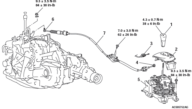
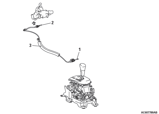
Selector lever assembly and transaxle control cable assembly removal steps
- Move the selector lever to the N position.
- Selector lever knob
- Shift indicator panel
- Key interlock cable connection (selector lever side)
- transaxle control cable connection (selector lever side)
- Connectors and harnesses connections
- Selector lever assembly
- Battery and battery tray
- Air Cleaner
- transaxle control cable connection (transaxle side)
- Heater unit assembly
- transaxle control cable
INSTALLATION SERVICE POINT
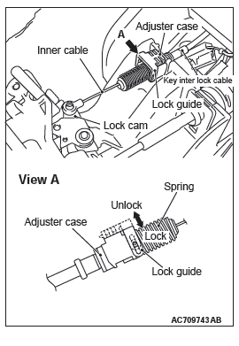
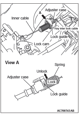
KEY INTERLOCK CABLE INSTALLATION
CAUTION Leave the ignition switch in the LOCK (OFF) position until the key interlock cable installation is completed.
1. Move the selector lever to the P position and turn the ignition switch to the LOCK (OFF) position.
2. Install the tip of the key interlock cable to the lock cam of the selector lever assembly, taking care not to twist the inner cable.
3. Install the adjuster case with its lock guide pulled up (unlocked).
4. Securely push down the lock guide to lock it.
NOTE: The lock position of the key interlock cable is automatically adjusted by a spring.
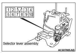
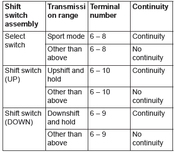
SHIFT SWITCH ASSEMBLY CONTINUITY CHECK
CVT Key Interlock and Shift Lock Mechanisms
REMOVAL AND INSTALLATION
Pre-removal operation
- Steering column lower cover and side lower panel assembly removal
- Front floor console assembly removal
Post-installation operation
- Steering column lower cover and side lower panel assembly installation
- Front floor console assembly installation
- Key interlock mechanism check
- Shift lock mechanism check
- Selector lever operation check
Removal steps
- Key interlock cable connection (selector lever side)
- Key interlock cable connection (steering side)
- Key interlock cable
REMOVAL SERVICE POINT
KEY INTERLOCK CABLE (STEERING SIDE) REMOVAL
Turn the ignition switch to the ACC position and then pull the key interlock cable out from the ignition key cylinder.
INSTALLATION SERVICE POINTS
KEY INTERLOCK CABLE (STEERING LOCK CYLINDER SIDE) INSTALLATION
Turn the ignition switch to the ACC position and then install the key interlock cable to the ignition key cylinder.
KEY INTERLOCK CABLE INSTALLATION
CAUTION Leave the ignition switch in the LOCK (OFF) position until the key interlock cable installation is completed.
1. Move the selector lever to the P position and turn the ignition switch to the LOCK (OFF) position.
2. Install the tip of the key interlock cable to the lock cam of the selector lever assembly, taking care not to twist the inner cable.
3. Install the adjuster case with its lock guide pulled up (unlocked).
4. Securely push down the lock guide to lock it.
NOTE: The lock position of the key interlock cable is automatically adjusted by a spring.
READ NEXT:
 Transaxle Assembly
REMOVAL AND INSTALLATION
CAUTION
The parts indicated by the * are the bolts with friction coefficient stabilizer.
In removal, ensure there is
no damage, clean dust and soiling from bearing and threa
Continuously
Variable
Transaxle
Overhaul
General Information
TRANSAXLE MODELS
SECTIONAL VIEW <TRANSAXLE>
<F1CJA>
<W1CJA>
SECTIONAL VIEW <TRANSFER>
General Specifications
Service Specifications
Fastener Tightenin
Transaxle
DISASSEMBLY AND ASSEMBLY
CAUTION
Only use transmission fluid of the specified brand. Use of
transmission fluid other than specified
will impair driveability and CVT endurance, and may lead to bre
SEE MORE:
Basic Brake System
Diagnosis
INTRODUCTION TO BASIC BRAKE SYSTEM DIAGNOSIS
Hydraulic brakes are composed of the brake pedal,
master cylinder, brake booster and disc brakes. Malfunctions
such as insufficient braking power or the
generation of noise may occur due to wear, damage
or incorrect adjustment of these components.
BASIC B
Power Steering Hoses
REMOVAL AND INSTALLATION
Pre-removal operation
Power Steering Fluid Draining
Engine room Under Cover Front (A,B,C), Engine room
Side Cover, Engine room Under Cover Rear Removal
Propeller Shaft Assembly Removal
Front Exhaust Pipe Removal
Front Roll Stopper And Centermember Assembly Removal
