Mitsubishi Outlander: Transaxle Control
REMOVAL AND INSTALLATION
WARNING
When removing and installing the transaxle control cable and shift lock cable unit, be careful not to hit the SRS-ECU.
Pre-removal operation
- Front floor console assembly removal
Post-installation operation
- Front floor console assembly installation
- Key interlock mechanism check
- Shift lock mechanism check
- Selector lever operation check
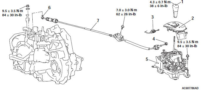
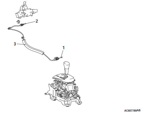
Selector lever assembly and transaxle control cable assembly removal steps
- Move the selector lever to the "N" position.
- Selector lever knob
- Shift indicator panel
- Key interlock cable connection (selector lever side)
- Transaxle control cable connection (selector lever side)
- Connectors and harnesses connections
- Selector lever assembly
- Battery and battery tray
- Air Cleaner
- Transaxle control cable connection (transaxle side)
- Heater unit assembly
- Transaxle control cable
REMOVAL SERVICE POINT
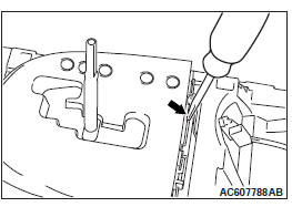
SHIFT INDICATOR PANEL REMOVAL
Insert the slotted head screwdriver into the arrow-indicated point as shown in the figure to pry the claw, and then remove the shift indicator panel.
INSTALLATION SERVICE POINTS
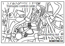
TRANSAXLE CONTROL CABLE (TRANSAXLE SIDE) INSTALLATION
1. Move the selector lever and manual control lever to the N position.
2. Use the adjusting nut to tighten the transaxle control cable to the specified torque.
Tightening torque: 9.5 +- 3.5 N*m (84 +- 30 in-lb)
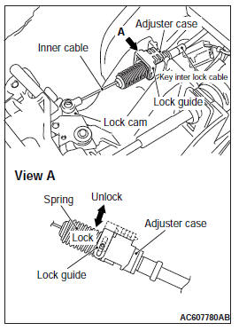
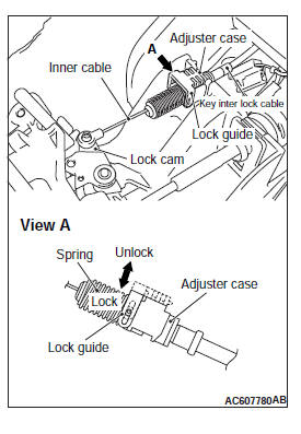
KEY INTERLOCK CABLE INSTALLATION
CAUTION Leave the ignition switch in the "LOCK" (OFF) position until the key interlock cable installation is completed.
1. Move the selector lever to the "P" position and turn the ignition switch to the "LOCK" (OFF) position.
2. Install the tip of the key interlock cable to the lock cam of the selector lever assembly, taking care not to twist the inner cable.
3. Install the adjuster case with its lock guide pulled up (unlocked).
4. Securely push down the lock guide to lock it.
NOTE: The lock position of the key interlock cable is automatically adjusted by a spring.
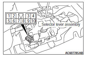
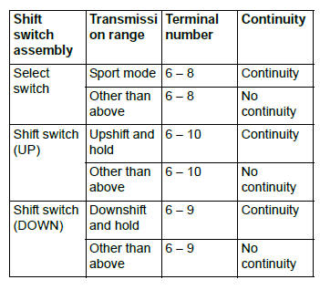
SHIFT SWITCH ASSEMBLY CONTINUITY CHECK
A/T Key Interlock and Shift Lock Mechanisms
REMOVAL AND INSTALLATION
WARNING When removing and installing the transaxle control cable and shift lock cable unit, be careful not to hit the SRS-ECU.
Pre-removal operation
- Steering column lower cover and side lower panel assembly removal
- Front floor console assembly removal
Post-installation operation
- Steering column lower cover and side lower panel assembly installation
- Front floor console assembly installation
- Key interlock mechanism check
- Shift lock mechanism check
- Selector lever operation check
Removal steps
- Key interlock cable connection (selector lever side)
- Key interlock cable connection (steering side)
- Key interlock cable
REMOVAL SERVICE POINT
KEY INTERLOCK CABLE (STEERING SIDE) REMOVAL
Turn the ignition switch to the "ACC" position and then pull the key interlock cable out from the ignition key cylinder.
INSTALLATION SERVICE POINTS
KEY INTERLOCK CABLE (STEERING LOCK CYLINDER SIDE) INSTALLATION
Turn the ignition switch to the "ACC" position and then install the key interlock cable to the ignition key cylinder.
KEY INTERLOCK CABLE INSTALLATION
CAUTION Leave the ignition switch in the "LOCK" (OFF) position until the key interlock cable installation is completed.
1. Move the selector lever to the P position and turn the ignition switch to the "LOCK" (OFF) position.
2. Install the tip of the key interlock cable to the lock cam of the selector lever assembly, taking care not to twist the inner cable.
3. Install the adjuster case with its lock guide pulled up (unlocked).
4. Securely push down the lock guide to lock it.
NOTE: The lock position of the key interlock cable is automatically adjusted by a spring.
READ NEXT:
 Transaxle Assembly
REMOVAL AND INSTALLATION
Pre-removal operation
Engine compartment under cover and side cover removal
Transmission fluid draining
Air cleaner bracket removal
Battery and Battery Tray Removal
ECM
Automatic Transaxle Overhaul
Transaxle Models
General Specifications
Service Specifications
Torque Specifications
Transaxle
Transfer
Size of torque wrench used
Adjusting Plate, Snap Ring,
Shim, Spacer, Needle Bearing,
Thrus
Transaxle
DISASSEMBLY AND ASSEMBLY
CAUTION
Use a fluid of the designated brand for transmission fluid. Use of
transmission fluid not specified
by the manufacturer can affect driveability and the durability
SEE MORE:
Headlamp washer switch
The headlamp washer can be operated with the ignition switch in the “ON” or “ACC”
position and the lamp switch at the position.
Push the button once and the washer fluid will be sprayed on to the headlamps.
NOTE:
● If the ignition switch is in the “ON” or “ACC” position
Starting the engine
[For vehicles equipped with the keyless operation system].
For information on operations for vehicles equipped with the keyless operation
system, refer to “Keyless operation system:
Starting”, 1-30.
[Except for vehicles equipped with the keyless operation system].
Tips for starting
Do not
