Mitsubishi Outlander: DTC B2412, B2413, B2415, B2416, C1608, C1900, C1901, C1910, C1920, C1930, C1940, C1911, C1921, C1931, C1941, C1912, C1922, C1932, C1942, C1913, C1923, C1933, C1943, C1914, C1924, C1934, C1944
DTC B2412 Antenna power voltage
CAUTION
- If diagnostic trouble code No. B2412 is set, diagnose the CAN bus lines.
- When replacing the ECU, always check that the communication circuit is normal.
Antenna Assembly Circuit
DIAGNOSTIC FUNCTION
If KOS-ECU detects an abnormality in power supply of the exterior or interior antennas, KOS-ECU sets diagnostic trouble code No. B2412.
JUDGMENT CRITERIA
If an abnormality in power supply of the outside or inside transmission antenna assembly is detected when power supply of it is turned on, KOS-ECU determines that there is a problem.
PROBABLE CAUSES
- Damaged wiring harness and connectors
- Malfunction of the KOS-ECU
DIAGNOSTIC PROCEDURE
Required Special Tools:
- MB991223: Harness Set
- MB992006: Extra Fine Probe
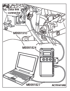
- MB991958: Scan Tool (M.U.T.-III Sub Assembly)
- MB991824: V.C.I.
- MB991827: M.U.T.-III USB Cable
- MB991910: M.U.T.-III Main Harness A
STEP 1. Using scan tool MB991958, read CAN bus the diagnostic trouble code.
CAUTION To prevent damage to scan tool MB991958, always turn the ignition switch to the "LOCK" (OFF) position before connecting or disconnecting scan tool MB991958.
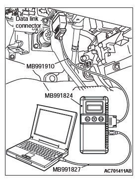
- Connect scan tool MB991958. Refer to "How to connect scan tool (M.U.T.-III)".
- Turn the ignition switch to the "ON" position.
- Check whether the CAN bus lines related DTC is set.
- Turn the ignition switch to the "LOCK" (OFF) position.
Q: Is the DTC set?
YES : Repair the CAN bus line (Refer to GROUP 54C, CAN bus diagnostics table).
NO : Go to Step 2.
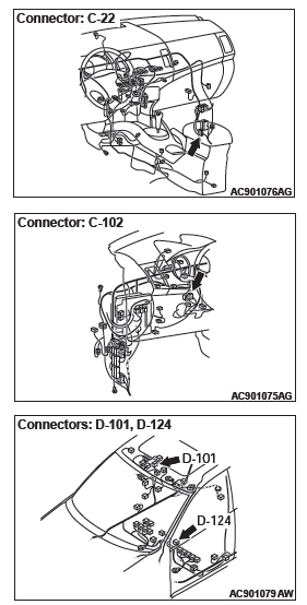
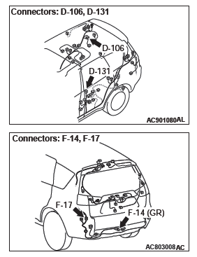
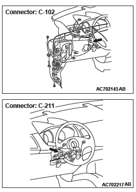
STEP 2. Check KOS-ECU connector C-102 for loose, corroded or damaged terminals, or terminals pushed back in the connector.
Q: Is KOS-ECU connector C-102 in good condition?
YES : Go to Step 3.
NO : Repair or replace the damaged component(s).
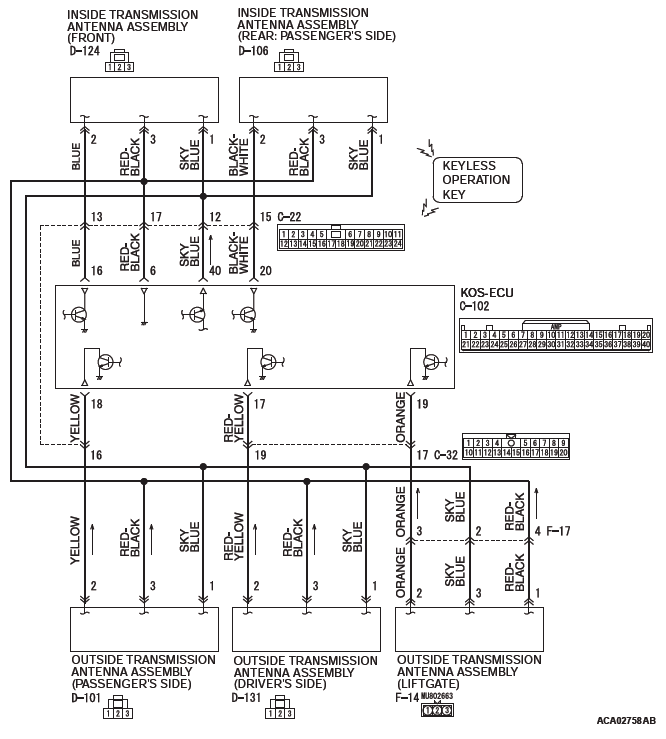
STEP 3. Check the wiring harness between KOS-ECU and each interior and exterior antenna.
Check the following wiring harnesses for open circuit and short to ground.
- Wiring harness between KOS-ECU connector C-102 (terminal No. 40) and outside transmission antenna assembly (driver's side) connector D-131 (terminal No. 1)
- Wiring harness between KOS-ECU connector C-102 (terminal No. 40) and outside transmission antenna assembly (front passenger's side) connector D-101 (terminal No. 1)
- Wiring harness between KOS-ECU connector C-102 (terminal No. 40) and inside transmission antenna assembly (front) connector D-124 (terminal No. 1)
- Wiring harness between KOS-ECU connector C-102 (terminal No. 40) and inside transmission antenna assembly (rear: front passenger's side) connector D-106 (terminal No.1)
- Wiring harness between KOS-ECU connector C-102 (terminal No. 40) and outside transmission antenna assembly (liftgate) connector F-14 (terminal No. 3)
NOTE: Also check intermediate connectors C-22 and F-17 for loose, corroded, or damaged terminals, or terminals pushed back in the connector. If intermediate connectors C-22 and F-17 is damaged, repair or replace the damaged component(s) as described in GROUP 00E, Harness Connector Inspection.
Q: Are the wiring harness between KOS-ECU connector C-102 and each interior and exterior antenna in good condition?
YES : Go to Step 4.
NO : The wiring harness may be damaged or the connector(s) may have loose, corroded or damaged terminals, or terminals pushed back in the connector.
Repair the wiring harness as necessary.
STEP 4. Check whether the diagnostic trouble code is reset.
- Erase the diagnostic trouble code.
- Turn the ignition switch from the LOCK (OFF) position to the ON position.
- Check if the diagnostic trouble code is set.
Q: Is the diagnostic trouble code set?
YES : Replace KOS-ECU and register the ID codes.
NO : The procedure is complete.
DTC B2413: STL unit power voltage
CAUTION
- If the DTC B2413 is set, diagnose the CAN bus lines. If there is any fault in the CAN bus lines, an incorrect diagnostic trouble code may be set. In this case, the set DTC is not highly reliable.
- Whenever the steering lock unit (integrated in the key reminder switch) is replaced, ensure that the communication circuit is normal.
Key Reminder Switch and KOS-ECU Circuit

DTC SET CONDITION
If KOS-ECU detects an abnormality in power supply of the steering lock unit, KOS-ECU sets the DTC B2413.
TECHNICAL DESCRIPTION (COMMENT)
If an abnormality in power supply of the steering lock unit is detected when power supply of it is turned on, KOS-ECU determines that there is a problem.
TROUBLESHOOTING HINTS
- Damaged wiring harness and connectors
- Malfunction of the steering lock unit (integrated into the key reminder switch)
- Malfunction of the KOS-ECU
DIAGNOSIS
Required Special Tools:
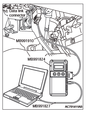
- MB991958: Scan Tool (M.U.T.-III Sub Assembly)
- MB991824: Vehicles Communication Interface (V.C.I.)
- MB991827: M.U.T.-III USB Cable
- MB991910: M.U.T.-III Main Harness A (Vehicles with CAN communication system)
STEP 1. Using scan tool MB991958, diagnose the CAN bus line.
CAUTION To prevent damage to scan tool (MB991958), always turn the ignition switch to the "LOCK" (OFF) position before connecting or disconnecting scan tool (MB991958).
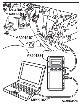
- Connect scan tool MB991958 to the data link connector.
- Turn the ignition switch to the "ON" position.
- Diagnose the CAN bus line.
- Turn the ignition switch to the "LOCK" (OFF) position.
Q: Is the CAN bus line found to be normal?
YES : Go to Step 2.
NO : Repair the CAN bus line.
STEP 2. Check key reminder switch connector C-211 for loose, corroded or damaged terminals, or terminals pushed back in the connector.
Q: Is the key reminder switch connector C-211 in good condition?
YES : Go to Step 3.
NO : Repair the defective connector.
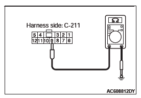
STEP 3. Check the power supply circuit to the key reminder switch. Measure the voltage at key reminder switch connector C-211.
NOTE: Check the power supply line for open circuit and short circuit.
- Disconnect the connector, and measure at the harness side.
- Turn the ignition push switch to the ON position.
- Measure the voltage between terminal No. 9 and ground.
- The voltage should measure 5 +- 0.5 volts.
Q: Is the measured voltage 5 +- 0.5 volts?
YES : Go to Step 4.
NO : Check the KOS-ECU connector C-102 and the wiring harness between the KOS-ECU connector C-102 (terminal No. 5) and the key reminder switch connector C-211 (terminal No. 9), and repair them if necessary. If it is normal, replace KOS-ECU and register the ID codes.
STEP 4. Check KOS-ECU connector C-102 for loose, corroded or damaged terminals, or terminals pushed back in the connector.
Q: Is the KOS-ECU connector C-102 in good condition?
YES : Go to Step 5.
NO : Repair the defective connector.
STEP 5. Check the wiring harness between the key reminder switch connector C-211 (terminal No. 11) and the KOS-ECU connector C-102 (terminal No. 31).
Check the ground wires for open circuit.
Q: Is the wiring harness between key reminder switch connector C-211 (terminal No. 11) and the KOS-ECU connector C-102 (terminal No. 31) in good condition?
YES : Go to Step 6.
NO : The wiring harness may be damaged or the connector(s) may have loose, corroded or damaged terminals, or terminals pushed back in the connector.
Repair the wiring harness as necessary.
STEP 6. Replace the key reminder switch, and check whether the diagnostic trouble code is reset.
- Erase the DTC.
- Turn the ignition switch from the "LOCK" (OFF) position to the "ON" position.
- Check if the DTC is set.
Q: Is the DTC set?
YES : Replace KOS-ECU and register the ID codes.
NO : The procedure is complete.
DTC B2415: RA module power voltage
CAUTION
- If DTC B2415 is set, diagnose the CAN bus lines.
- When replacing the ECU, always check that the communication circuit is normal.
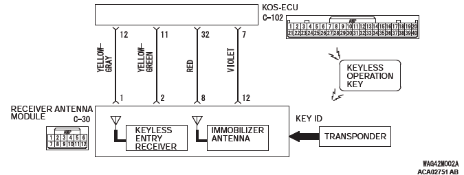
Receiver Antenna Module and KOS-ECU Circuit
DTC SET CONDITION
If KOS-ECU detects an abnormality in power supply of the receiver antenna module, KOS-ECU sets DTC No. B2415.
TECHNICAL DESCRIPTION (COMMENT)
When the ignition switch is turned to ON, KOS-ECU transmits the signal to the receiver antenna module.
The receiver antenna module transmits random numbers to the keyless operation key when it receives signals from KOS-ECU. If an open circuit or short to ground occurs on the wiring harness between KOS-ECU and receiver antenna module at this time, KOS-ECU determines that there is a problem.
TROUBLESHOOTING HINTS
- Malfunction of CAN bus line
- Damaged wiring harness and connectors
- Malfunction of the receiver antenna module
- Malfunction of KOS-ECU
DIAGNOSIS
Required Special Tools:
- MB991958: Scan Tool (M.U.T.-III Sub Assembly)
- MB991824: Vehicles Communication Interface (V.C.I.)
- MB991827: M.U.T.-III USB Cable
- MB991910: M.U.T.-III Main Harness A (Vehicles with CAN communication system)
STEP 1. Using scan tool MB991958, diagnose the CAN bus line.
CAUTION To prevent damage to scan tool (MB991958), always turn the ignition switch to the "LOCK" (OFF) position before connecting or disconnecting scan tool (MB991958).
- Connect scan tool MB991958 to the data link connector.
- Turn the ignition switch to the "ON" position.
- Diagnose the CAN bus line.
- Turn the ignition switch to the "LOCK" (OFF) position.
Q: Is the CAN bus line found to be normal?
YES : Go to Step 2.
NO : Repair the CAN bus line.
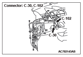
STEP 2. Check receiver antenna module connector C-30 and KOS-ECU connector C-102 for loose, corroded or damaged terminals, or terminals pushed back in the connector.
Q: Is the receiver antenna module connector C-30 and KOS-ECU connector C-102 in good condition?
YES : Go to Step 3.
NO : Repair the defective connector.
STEP 3. Check the wiring harness between the receiver antenna module connector C-30 (terminal No. 8, 12) and the KOS-ECU connector C-102 (terminal No. 32, 7).
Check the power supply and ground wires for open circuit or power supply wires for ground circuit.
Q: Is the wiring harness between receiver antenna module connector C-30 (terminal No. 8, 12) and the KOS-ECU connector C-102 (terminal No. 32, 7) in good condition?
YES : Go to Step 4.
NO : The wiring harness may be damaged or the connector(s) may have loose, corroded or damaged terminals, or terminals pushed back in the connector.
Repair the wiring harness as necessary.
STEP 4. Replace the receiver antenna module, and check whether the diagnostic trouble code is reset.
- Turn the ignition switch from the "LOCK" (OFF) position to the "ON" position.
- Check if the DTC is set.
Q: Is the DTC set?
YES : Replace KOS-ECU and register the ID codes. NO : The trouble can be an intermittent malfunction.
DTC B2416: ECU internal error
DTC SET CONDITION
KOS-ECU sets DTC B2416 when it determines itself to be in abnormal status.
TECHNICAL DESCRIPTION (COMMENT)
KOS-ECU determines that the abnormality is present, if the data abnormality is found when the ignition switch is turned ON and then EEPROM is written.
TROUBLESHOOTING HINTS
Malfunction of KOS-ECU
DIAGNOSIS
Required Special Tools:
- MB991958: Scan Tool (M.U.T.-III Sub Assembly)
- MB991824: Vehicles Communication Interface (V.C.I.)
- MB991827: M.U.T.-III USB Cable
- MB991910: M.U.T.-III Main Harness A (Vehicles with CAN communication system)
Recheck for diagnostic trouble code.
Check again if the DTC is set to the KOS-ECU.
CAUTION To prevent damage to scan tool (MB991958), always turn the ignition switch to the "LOCK" (OFF) position before connecting or disconnecting scan tool (MB991958).
- Connect scan tool MB991958 to the data link connector.
- Erase the DTC.
- Turn the ignition switch from "LOCK" (OFF) position to "ON" position.
- Check if DTC is set.
- Turn the ignition switch to the "LOCK" (OFF) position.
Q: Is the DTC set?
YES : Replace KOS-ECU and register the ID codes.
NO : The trouble can be an intermittent malfunction.
DTC C1608: EEPROM Error
CAUTION If there is any problem in the CAN bus lines, an incorrect diagnostic trouble code may be set. Prior to this diagnosis, diagnose the CAN bus lines.
DTC SET CONDITION
KOS incorporates EEPROM (nonvolatile memory), and that EEPROM stores the TPMS, KOS and immobilizer information.
When the data in EEPROM is failed, this code is set.
TROUBLESHOOTING HINTS
The most likely causes for this DTC to set are:
- Damaged wiring harness and connector
- Malfunction of KOS-ECU
DIAGNOSIS
Required Special Tools:
- MB991958: Scan Tool (M.U.T.-III Sub Assembly)
- MB991824: Vehicle Communication Interface (V.C.I.)
- MB991827: M.U.T.-III USB Cable
- MB991910: M.U.T.-III Main Harness A
STEP 1. Using scan tool MB991958, diagnose the CAN bus line.
Use scan tool to diagnose the CAN bus lines.
Q: Is the check result normal?
YES : Go to Step 2.
NO : Repair the CAN bus lines. On completion, go to Step 2.
STEP 2. Diagnostic trouble code check
- Turn the ignition switch to the "LOCK" (OFF) position.
- Turn the ignition switch to the "ON" position.
- Check if the DTC is set.
- Turn the ignition switch to the "LOCK" (OFF) position.
Q: Is the DTC C1608 set?
YES : Replace the KOS-ECU and register the ID codes. Then go to Step 3.
NO : The procedure is complete.
STEP 3. Diagnostic trouble code check
- Turn the ignition switch to the "LOCK" (OFF) position.
- Turn the ignition switch to the "ON" position.
- Check if the DTC is set.
- Turn the ignition switch to the "LOCK" (OFF) position.
Q: Is the DTC C1608 set?
YES : Start over at Step 1.
NO : The procedure is complete.
DTC C1900: No registration
CAUTION If there is any problem in the CAN bus lines, an incorrect diagnostic trouble code may be set. Prior to this diagnosis, diagnose the CAN bus lines.
DTC SET CONDITION
When the ID registration information of the TPMS transmitter is not stored in KOS-ECU, and/or when KOS-ECU is replaced with a new one, this code is set. If the ID registration mode is terminated forcibly or time-out after one or more TPMS transmitters are registered in the ID registration mode, the ID information in the KOS-ECU is erased, and this diagnostic trouble code is set.
TROUBLESHOOTING HINTS
The most likely causes for this DTC to set are:
- Damaged wiring harness and connector
- Malfunction of TPMS transmitter
- Malfunction of KOS-ECU
- ID code registration failed
DIAGNOSIS
Required Special Tools:
- MB991958: Scan Tool (M.U.T.-III Sub Assembly)
- MB991824: Vehicle Communication Interface (V.C.I.)
- MB991827: M.U.T.-III USB Cable
- MB991910: M.U.T.-III Main Harness A
STEP 1. Using scan tool MB991958, diagnose the CAN bus line.
Use scan tool to diagnose the CAN bus lines.
Q: Is the check result normal?
YES : Go to Step 2.
NO : Repair the CAN bus lines. On completion, go to Step 2.
STEP 2. Diagnostic trouble code check
- Turn the ignition switch to the "LOCK" (OFF) position.
- Turn the ignition switch to the "ON" position.
- Check if the DTC is set.
- Turn the ignition switch to the "LOCK" (OFF) position.
Q: Is the DTC C1900 set?
YES : Register the ID codes. Then go to Step 3.
NO : The procedure is complete.
STEP 3. Recheck for diagnostic trouble code.
Check again if the DTC is set.
- Turn the ignition switch to the "LOCK" (OFF) position.
- Turn the ignition switch to the "ON" position.
- Check if the DTC is set.
- Turn the ignition switch to the "LOCK" (OFF) position.
Q: Is the DTC C1900 reset?
YES : Replace the KOS-ECU and register the ID codes. Then start over at Step 1.
NO : The procedure is complete.
DTC C1901: Vehicle speed information abnormality
CAUTION If there is any problem in the CAN bus lines, an incorrect diagnostic trouble code may be set. Prior to this diagnosis, diagnose the CAN bus lines.
DTC SET CONDITION
KOS-ECU receives the wheel speed information from ABS-ECU or ASC-ECU via the CAN-bus line. Although KOS-ECU receives the information that the wheel is not currently rotated from ABS-ECU or ASC-ECU, if the TPMS transmitter sends the information that the wheel is rotated, this code is set.
TROUBLESHOOTING HINTS
The most likely causes for this DTC to set are:
- Damaged wiring harness and connector
- Malfunction of TPMS transmitter
- Malfunction of KOS-ECU
- Malfunction of ABS-ECU or ASC-ECU
- Malfunction of ETACS-ECU
DIAGNOSIS
Required Special Tools:
- MB991958: Scan Tool (M.U.T.-III Sub Assembly)
- MB991824: Vehicle Communication Interface (V.C.I.)
- MB991827: M.U.T.-III USB Cable
- MB991910: M.U.T.-III Main Harness A
STEP 1. Using scan tool MB991958, diagnose the CAN bus line.
Use scan tool to diagnose the CAN bus lines.
Q: Is the check result normal?
YES : Go to Step 3.
NO : Repair the CAN bus lines (Refer to GROUP 54C − CAN Bus Diagnostics table). On completion, go to Step 2.
STEP 2. Diagnostic trouble code recheck after resetting CAN bus lines
- Turn the ignition switch to the "LOCK" (OFF) position.
- Turn the ignition switch to the "ON" position.
- Check if the DTC is set.
- Turn the ignition switch to the "LOCK" (OFF) position.
Q: Is the DTC C1901 set?
YES : Go to Step 3.
NO : The procedure is complete.
STEP 3. Check for other diagnostic trouble code.
Check if the diagnostic trouble code is set from ABS-ECU or ASC-ECU <Refer to GROUP 35B, diagnostic trouble code chart (vehicles without ASC) or Refer to GROUP 35C, diagnostic trouble code chart (vehicles with ASC)>.
Q: Is the check result normal?
YES : Go to Step 4.
NO : Carry out the troubleshooting for ABS-ECU or ASC-ECU <Refer to GROUP 35B, diagnostic trouble code chart (vehicles without ASC) or Refer to GROUP 35C, diagnostic trouble code chart (vehicles with ASC)>. Then go to Step 6.
STEP 4. Check for other diagnostic trouble code.
Check if the diagnostic trouble code is set from ETACS-ECU.
Q: Is the check result normal?
YES : Go to Step 5.
NO : Troubleshoot the set DTC.
Then go to Step 6.
STEP 5. Check the TPMS transmitter acceleration.
Check the acceleration value of each TPMS transmitter by the TPMS transmitter check function .
OK: Acceleration value: 5G or less
Q: Is the check result OK?
YES : Replace the KOS-ECU and register ID codes. Then go to Step 6.
NO : Replace the TPMS transmitter and register ID codes. Then go to Step 6.
STEP 6. Recheck for diagnostic trouble code.
- Turn the ignition switch to the "LOCK" (OFF) position.
- Turn the ignition switch to the "ON" position.
- Check if the DTC is set.
- Turn the ignition switch to the "LOCK" (OFF) position.
Q: Is the DTC C1901 set?
YES : Start over at Step 1.
NO : The procedure is complete.
DTC C1910: Transmitter low battery voltage abnormality 1
DTC C1920: Transmitter low battery voltage abnormality 2
DTC C1930: Transmitter low battery voltage abnormality 3
DTC C1940: Transmitter low battery voltage abnormality 4
DTC C1911: Reception abnormality 1
DTC C1921: Reception abnormality 2
DTC C1931: Reception abnormality 3
DTC C1941: Reception abnormality 4
CAUTION If there is any problem in the CAN bus lines, an incorrect diagnostic trouble code may be set. Prior to this diagnosis, diagnose the CAN bus lines.
DTC SET CONDITION
DTC C1910, C1920, C1930, C1940
- When the reception abnormality warning is activated because of the low battery voltage of the TPMS transmitter.
DTC C1911, C1921, C1931, C1941
- When KOS-ECU cannot receive the signals from the TPMS transmitters while driving for about 20 minutes, this code is set.
TROUBLESHOOTING HINTS
The most likely causes for this DTC to set are:
- Low battery that is incorporated into the TPMS transmitter
- Damaged wiring harness and connector
- Registered IDs unmatched
- Malfunction of TPMS transmitter
- Malfunction of KOS-ECU
DIAGNOSIS
Required Special Tools:
- MB991958: Scan Tool (M.U.T.-III Sub Assembly)
- MB991824: Vehicle Communication Interface (V.C.I.)
- MB991827: M.U.T.-III USB Cable
- MB991910: M.U.T.-III Main Harness A
STEP 1. Using scan tool MB991958, diagnose the CAN bus line.
Use scan tool to diagnose the CAN bus lines.
Q: Is the check result normal?
YES : Go to Step 3.
NO : Repair the CAN bus lines. On completion, go to Step 2.
STEP 2. Diagnostic trouble code recheck after resetting CAN bus lines
Q: Is the DTC C1910, C1920, C1930, C1940, C1911, C1921, C1931 or C1941 set?
YES : Go to Step 3.
NO : The procedure is complete.
STEP 3. Check for TPMS transmitter.
Identify the TPMS transmitter which the DTC is set by TPMS transmitter check.
NOTE: The TPMS transmitter which cannot be checked may be faulty or the ID code may not be registered, thus do not replace it, but register the ID code. If the transmitter is faulty, it is replaced in the ID code registration process.
Q: Are there any TPMS transmitters which are identified?
YES : Among the checked TPMS transmitters, replace the TPMS transmitters to which the DTC is set. Then register the ID codes. Then go to Step 4.
NO : Even when no transmitter is checked, register the ID codes. Then go to Step 4.
STEP 4. Diagnostic trouble code recheck after register the ID codes
- Turn the ignition switch to the "LOCK" (OFF) position.
- Turn the ignition switch to the "ON" position.
- Check if the DTC is set.
- Turn the ignition switch to the "LOCK" (OFF) position.
Q: Is the DTC C1910, C1920, C1930, C1940, C1911, C1921, C1931 or C1941 set?
YES : Replace the KOS-ECU and register the ID codes. Then start over at Step 1.
NO : The procedure is complete.
DTC C1912: Tire inflation pressure warning 1
DTC C1922: Tire inflation pressure warning 2
DTC C1932: Tire inflation pressure warning 3
DTC C1942: Tire inflation pressure warning 4
CAUTION If there is any problem in the CAN bus lines, an incorrect diagnostic trouble code may be set. Prior to this diagnosis, diagnose the CAN bus lines.
DTC SET CONDITION
When the tire pressure included in the signal from the TPMS transmitter is less than the specified value, KOS-ECU sets this code.
TROUBLESHOOTING HINTS
The most likely causes for this DTC to set is:
- Drop of tire pressure
- Loose TPMS transmitter mounting nut
- Flat tire
- TPMS transmitter malfunction
- KOS-ECU malfunction
- CAN-bus line malfunction
DIAGNOSIS
Required Special Tools:
- MB991958: Scan Tool (M.U.T.-III Sub Assembly)
- MB991824: Vehicle Communication Interface (V.C.I.)
- MB991827: M.U.T.-III USB Cable
- MB991910: M.U.T.-III Main Harness A
STEP 1. Using scan tool MB991958, diagnose the CAN bus line.
Use scan tool to diagnose the CAN bus lines.
Q: Is the check result normal?
YES : Go to Step 3.
NO : Repair the CAN bus lines. On completion, go to Step 2.
STEP 2. Diagnostic trouble code recheck after resetting CAN bus lines
Q: Is DTC C1912, C1922, C1932 or C1942 set?
YES : Go to Step 3.
NO : The procedure is complete.
STEP 3. Tire check
Check that there is no abnormality for the items below.
- Flat tire
- Cracked tire
- Air leak from valve
- Loose TPMS transmitter mounting nut
Q: Is the check result normal?
YES : Go to Step 4.
NO : Repair or replace it. Then go to Step 4.
STEP 4. Diagnostic trouble code check
- Turn the ignition switch to the "ON" position, and adjust the pressure to the recommended tire pressure.
- Check if the DTC is set.
Q: Is DTC C1912, C1922, C1932 or C1942 set?
YES : Go to Step 5.
NO : The procedure is complete.
STEP 5. Diagnostic trouble code check
- Drive the vehicle for five minutes.
NOTE: Even within 5 minutes, if the TPMS warning light goes out, finish the driving and perform the operation (2).
- Check if the DTC is set.
Q: Is DTC C1912, C1922, C1932 or C1942 set?
YES : Go to Step 6.
NO : The procedure is complete.
STEP 6. Tire pressure check by scan tool
- Perform the transmitter check using the scan tool, and check the tire pressure values of all the wheels.
- Check the tire pressure of all the wheels using the tire pressure gauge.
- Compare the measured value (1) with (2).
OK: 20 kPa (2.9 psi) or less NOTE: Do not replace the TPMS transmitter which cannot be checked.
Q: Is the check result OK?
YES : Replace the KOS-ECU and register the ID codes. Then go to Step 9.
NO : Go to Step 7.
STEP 7. Tire pressure check by scan tool
- Perform the transmitter check using the scan tool, and check the tire pressure values of all the wheels.
- Check the tire pressure of all the wheels using the tire pressure gauge.
- Compare the measured value (1) with (2).
OK: 20 kPa (2.9 psi) or less Q: Is the check result OK?
YES : Replace the KOS-ECU and register the ID codes. Then go to Step 9.
NO : Replace the TPMS transmitter and register the ID codes. Then go to Step 8.
STEP 8. Recheck for diagnostic trouble code.
- Turn the ignition switch to the "LOCK" (OFF) position.
- Turn the ignition switch to the "ON" position.
- Check if the DTC is set.
- Turn the ignition switch to the "LOCK" (OFF) position.
Q: Is the DTC C1912, C1922, C1932 or C1942 set?
YES : Replace the KOS-ECU and register the ID codes. Then go to Step 9.
NO : The procedure is complete.
STEP 9. Recheck for diagnostic trouble code.
- Turn the ignition switch to the "LOCK" (OFF) position.
- Turn the ignition switch to the "ON" position.
- Check if the DTC is set.
- Turn the ignition switch to the "LOCK" (OFF) position.
Q: Is the DTC C1912, C1922, C1932 or C1942 set?
YES : Start over at Step 1.
NO : The procedure is complete.
DTC C1913: Acceleration sensor abnormality 1
DTC C1923: Acceleration sensor abnormality 2
DTC C1933: Acceleration sensor abnormality 3
DTC C1943: Acceleration sensor abnormality 4
DTC C1914: Pressure sensor abnormality 1
DTC C1924: Pressure sensor abnormality 2
DTC C1934: Pressure sensor abnormality 3
DTC C1944: Pressure sensor abnormality 4
CAUTION If there is any problem in the CAN bus lines, an incorrect diagnostic trouble code may be set. Prior to this diagnosis, diagnose the CAN bus lines.
DTC SET CONDITION
DTC C1913, C1923, C1933, C1943
- The TPMS transmitter detects if the wheel is rotated by the
acceleration sensor and sends the signals to KOS-ECU.
When the TPMS transmitter judges that the acceleration sensor is failed, the failure signal is send to KOS-ECU, and KOS-ECU sets this code.
DTC C1914, C1924, C1934, C1944
- The TPMS transmitter detects if the tire pressure sensor is normal and sends the signal to KOS-ECU. When the TPMS transmitter judges that the tire pressure sensor is failed, the failure signal is send to KOS-ECU, and KOS-ECU sets this code.
TROUBLESHOOTING HINTS
The most likely causes for this DTC to set are:
- Low battery that is incorporated into the TPMS transmitter
- Damaged wiring harness and connector
- Registered IDs unmatched
- Malfunction of TPMS transmitter
- Malfunction of KOS-ECU
DIAGNOSIS
Required Special Tools:
- MB991958: Scan Tool (M.U.T.-III Sub Assembly)
- MB991824: Vehicle Communication Interface (V.C.I.)
- MB991827: M.U.T.-III USB Cable
- MB991910: M.U.T.-III Main Harness A
STEP 1. Using scan tool MB991958, diagnose the CAN bus line.
Use scan tool to diagnose the CAN bus lines.
Q: Is the check result normal?
YES : Go to Step 3.
NO : Repair the CAN bus lines. On completion, go to Step 2.
STEP 2. Diagnostic trouble code recheck after resetting CAN bus lines
Q: Is the DTC C1913, C1923, C1933, C1943, C1914, C1924, C1934 or C1944 set?
YES : Go to Step 3.
NO : The procedure is complete.
STEP 3. Check for TPMS transmitter.
Identify the TPMS transmitter which the DTC is set by TPMS transmitter check.
NOTE: The TPMS transmitter which cannot be checked may be faulty or the ID code may not be registered, thus do not replace it, but register the ID code. If the transmitter is faulty, it is replaced in the ID code registration process.
Q: Are there any TPMS transmitters which are identified?
YES : Among the checked TPMS transmitters, replace the TPMS transmitters to which the DTC is set. Then register the ID codes. Then go to Step 4.
NO : Even when no transmitter is checked, register the ID codes. Then go to Step 4.
STEP 4. Diagnostic trouble code recheck after register the ID codes
- Turn the ignition switch to the "LOCK" (OFF) position.
- Turn the ignition switch to the "ON" position.
- Check if the DTC is set.
- Turn the ignition switch to the "LOCK" (OFF) position.
Q: Is the DTC C1913, C1923, C1933, C1943, C1914, C1924, C1934 or C1944 set?
YES : Replace the KOS-ECU and register the ID codes. Then start over at Step 1.
NO : The procedure is complete.
READ NEXT:
 DTC C1915, C1925, C1935, C1945, U0019, U0141, U0151, U0154, U0155, U0164, U0184,
U0245, U1412, U1415, U1417
DTC C1915, C1925, C1935, C1945, U0019, U0141, U0151, U0154, U0155, U0164, U0184,
U0245, U1412, U1415, U1417
DTC C1915: Transmitter OFF mode 1
DTC C1925: Transmitter OFF mode 2
DTC C1935: Transmitter OFF mode 3
DTC C1945: Transmitter OFF mode 4
CAUTION
If there is any problem in the CAN bus lines, an incorre
Inspection Procedure 1-9
Inspection Procedure 1: Cannot communicate with KOS-ECU using the scan
tool.
CAUTION
Before replacing the ECU, ensure that the communication
circuit is normal.
TECHNICAL DESCRIPTION (COMMENT)
If the
Inspection Procedure 10-18
Inspection Procedure 10: The lock switch of the liftgate lock release
handle does not perform the
locking operation.
CAUTION
Before replacing the ECU, ensure that the power
supply circuit, the ground
SEE MORE:
On-vehicle Service
DRIVE BELT TENSION CHECK
1. Remove the radiator condenser tank mounting bolt, and
move the radiator condenser tank to a place where it does
not interfere with the drive belt tension check.
CAUTION
Check the drive belt tension after turning the crankshaft
clockwise one turn or more.
2. Make sure tha
Rear Disc Brake Assembly
REMOVAL AND INSTALLATION <2.4L ENGINE: 5 PERSONS SEAT>
Pre-removal operation
Brake Fluid Draining
Post-installation operation
Brake Fluid Refilling and Air Bleeding
Brake Disk Runout Inspection/Correction
Parking Brake Lining Seating Procedure
Removal steps
Brake tube (brake hose s
