Mitsubishi Outlander: Inspection Procedure 10-18
Inspection Procedure 10: The lock switch of the liftgate lock release handle does not perform the locking operation.
CAUTION Before replacing the ECU, ensure that the power supply circuit, the ground circuit and the communication circuit are normal.
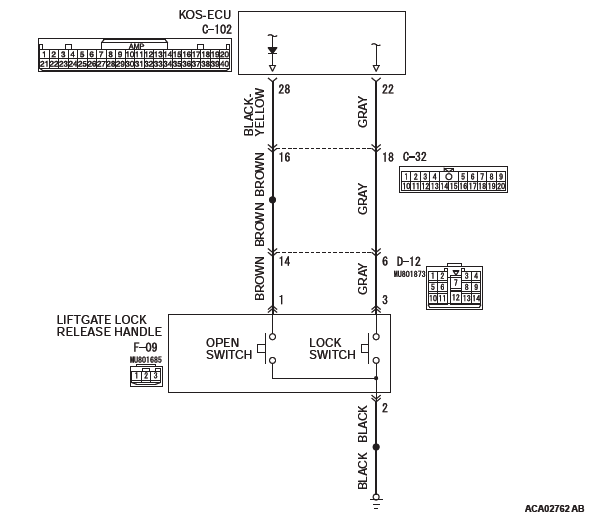
Liftgate Lock Release Handle Circuit
PROBABLE CAUSES
- Malfunction of the outside transmission antenna assembly (liftgate)
- Malfunction of the liftgate lock release handle (lock switch)
- Damaged wiring harness and connectors
- Malfunction of the KOS-ECU
DIAGNOSIS
STEP 1. Using scan tool MB991958, read the diagnostic trouble code.
CAUTION To prevent damage to scan tool MB991958, always turn the ignition switch to the "LOCK" (OFF) position before connecting or disconnecting scan tool MB991958.
- Connect scan tool MB991958. Refer to "How to connect scan tool (M.U.T.-III)".
- Turn the ignition switch to the "ON" position.
- Check whether the KOS-ECU related DTC is set.
- Turn the ignition switch to the "LOCK" (OFF) position.
Q: Is the DTC set?
YES : Diagnose the KOS-ECU.
NO : Go to Step 2.
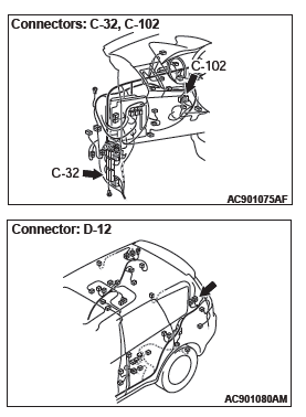
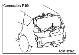
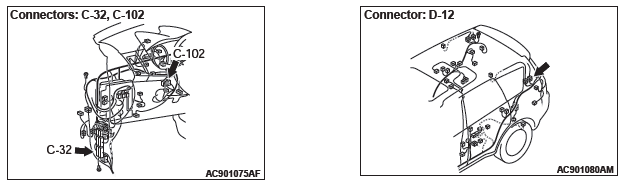
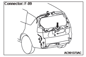
STEP 2. Check KOS-ECU connector C-102 and liftgate lock release handle connector F-09 for loose, corroded or damaged terminals, or terminals pushed back in the connector.
Q: Are KOS-ECU connector C-102 and liftgate lock release handle connector F-09 in good condition?
YES : Go to Step 3.
NO : Repair or replace the damaged component(s). Refer to GROUP 00E, Harness Connector Inspection. Check that the liftgate lock release handle works normally.
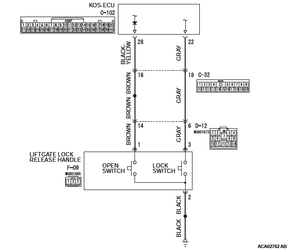
STEP 3. Check the wiring harness between KOS-ECU connector C-102 (terminal No. 22) and liftgate lock release handle connector F-09 (terminal No. 3).
Check the signal wires for open circuit.
NOTE: Also check intermediate connectors C-32, D-12 for loose, corroded, or damaged terminals, or terminals pushed back in the connector. If intermediate connectors C-32, D-12 is damaged, repair or replace the damaged component(s) as described in GROUP 00E, Harness Connector Inspection.
Q: Is the wiring harness between KOS-ECU connector C-102 (terminal No. 22) and liftgate lock release handle connector F-09 (terminal No. 3) in good condition?
YES : Go to Step 4.
NO : The wiring harness may be damaged or the connector(s) may have loose, corroded or damaged terminals, or terminals pushed back in the connector.
Repair the wiring harness as necessary. Check that the liftgate lock release handle works normally.
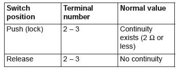
STEP 4. Liftgate lock release handle check
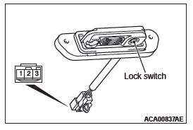
- Remove the liftgate lock release handle.
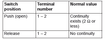
- Check continuity when the liftgate lock release handle is operated to "ON" or "OFF" position.
Q: Is the liftgate lock release handle normal?
YES : Go to Step 5.
NO : Replace the liftgate lock release handle. Check that the liftgate lock release handle works normally.
STEP 5. KOS communication test
Using scan tool (M.U.T-III), perform the antenna communication test to check that the outside transmission antenna assembly (liftgate) communicates normally.
Q: Is the check result normal?
YES : Go to Step 6 NO : Perform troubleshooting for the diagnostic trouble code No. B240C.
STEP 6. Check of the troubles
Operate the liftgate lock release handle and check that the liftgate can be locked.
Q: Is the check result normal?
YES : Intermittent malfunction is suspected.
NO : Replace KOS-ECU and register the ID codes.
Inspection Procedure 11: The open switch of the liftgate lock release handle does not perform the unlocking operation.
CAUTION Before replacing the ECU, ensure that the power supply circuit, the ground circuit and the communication circuit are normal.
Liftgate Lock Release Handle Circuit
PROBABLE CAUSES
- Malfunction of the outside transmission antenna assembly (liftgate)
- Malfunction of the liftgate lock release handle (open switch)
- Damaged wiring harness and connectors
- Malfunction of the KOS-ECU
DIAGNOSIS
STEP 1. Using scan tool MB991958, read the diagnostic trouble code.
CAUTION To prevent damage to scan tool MB991958, always turn the ignition switch to the "LOCK" (OFF) position before connecting or disconnecting scan tool MB991958.
- Connect scan tool MB991958. Refer to "How to connect scan tool (M.U.T.-III)".
- Turn the ignition switch to the "ON" position.
- Check whether the KOS-ECU related DTC is set.
- Turn the ignition switch to the "LOCK" (OFF) position.
Q: Is the DTC set?
YES : Diagnose the KOS-ECU. Refer to Diagnostic Trouble Code Chart.
NO : Go to Step 2.
STEP 2. Check KOS-ECU connector C-102 and liftgate lock release handle connector F-09 for loose, corroded or damaged terminals, or terminals pushed back in the connector.
Q: Are KOS-ECU connector C-102 and liftgate lock release handle connector F-09 in good condition?
YES : Go to Step 3.
NO : Repair or replace the damaged component(s). Refer to GROUP 00E, Harness Connector Inspection. Check that the liftgate lock release handle works normally.
STEP 3. Check the wiring harness between KOS-ECU connector C-102 (terminal No. 28) and liftgate lock release handle connector F-09 (terminal No. 1).
Check the signal wires for open circuit.
NOTE: Also check intermediate connectors C-32, D-12 for loose, corroded, or damaged terminals, or terminals pushed back in the connector. If intermediate connectors C-32, D-12 is damaged, repair or replace the damaged component(s) as described in GROUP 00E, Harness Connector Inspection.
Q: Is the wiring harness between KOS-ECU connector C-102 (terminal No. 28) and liftgate lock release handle connector F-09 (terminal No. 1) in good condition?
YES : Go to Step 4.
NO : The wiring harness may be damaged or the connector(s) may have loose, corroded or damaged terminals, or terminals pushed back in the connector.
Repair the wiring harness as necessary. Check that the liftgate lock release handle works normally.
STEP 4. Liftgate lock release handle check
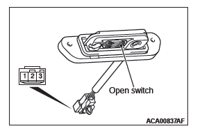
- Remove the liftgate lock release handle.
- Check continuity when the liftgate lock release handle is operated to "ON" or "OFF" position.
Q: Is the liftgate lock release handle normal?
YES : Go to Step 5.
NO : Replace the liftgate lock release handle. Check that the liftgate lock release handle works normally.
STEP 5. KOS communication test
Using scan tool (M.U.T-III), perform the antenna communication test to check that the outside transmission antenna assembly (liftgate) communicates normally.
Q: Is the check result normal?
YES : Go to Step 6 NO : Perform troubleshooting for the diagnostic trouble code No. B240C.
STEP 6. Check of the troubles
Operate the liftgate lock release handle and check that the liftgate can be opened.
Q: Is the check result normal?
YES : Intermittent malfunction is suspected.
NO : Replace KOS-ECU and register the ID codes.
Inspection Procedure 12: Keyless entry system does not work.
CAUTION Before replacing the ECU, ensure that the power supply circuit, the ground circuit and the communication circuit are normal.
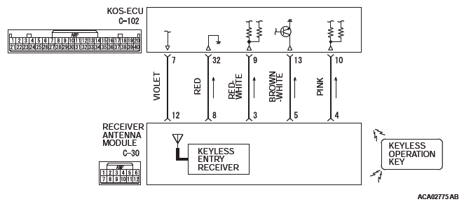
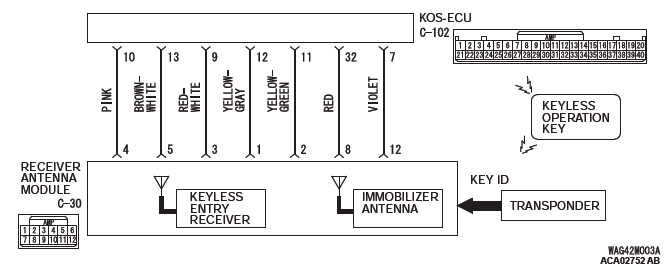
Receiver Antenna Module Circuit
OPERATION
The receiver antenna module receives lock and unlock signals from the keyless operation key, and sends them to KOS-ECU, and further to ETACS-ECU. Also, when ETACS receives signals from the key reminder switch and all the door switches, ETACS-ECU judges them to activate the keyless entry function.
PROBABLE CAUSES
- Malfunction of CAN bus line
- Malfunction of the door switches
- Malfunction of the key reminder switch
- Malfunction of the receiver antenna module
- Malfunction of the keyless operation key
- Damaged wiring harness and connectors
- Malfunction of the KOS-ECU
- Malfunction of ETACS-ECU
DIAGNOSTIC PROCEDURE
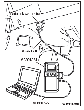
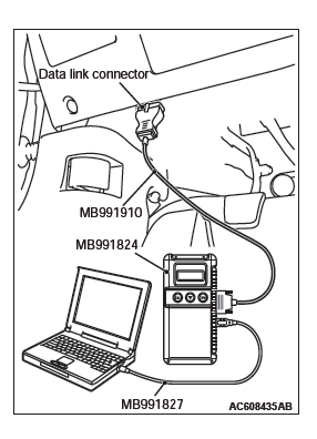
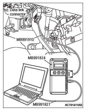
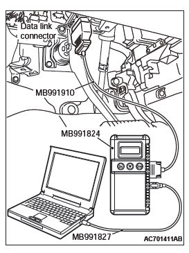
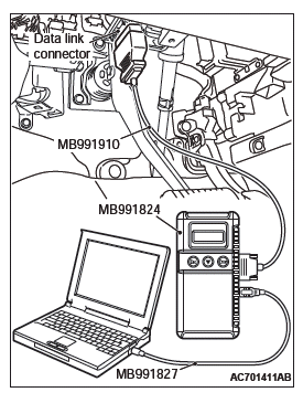
Required Special Tools:
- MB991223: Harness Set
- MB992006: Extra Fine Probe
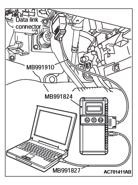
- MB991958: Scan Tool (M.U.T.-III Sub Assembly)
- MB991824: V.C.I.
- MB991827: M.U.T.-III USB Cable
- MB991910: M.U.T.-III Main Harness A
STEP 1. Using scan tool MB991958, read CAN bus the diagnostic trouble code.
CAUTION To prevent damage to scan tool MB991958, always turn the ignition switch to the "LOCK" (OFF) position before connecting or disconnecting scan tool MB991958.
- Connect scan tool MB991958. Refer to "How to connect scan tool (M.U.T.-III)".
- Turn the ignition switch to the "ON" position.
- Check whether the CAN bus lines related DTC is set.
- Turn the ignition switch to the "LOCK" (OFF) position.
Q: Is the DTC set?
YES : Repair the CAN bus line .
NO : Go to Step 2.
STEP 2. Using scan tool MB991958, read the diagnostic trouble code.
CAUTION To prevent damage to scan tool MB991958, always turn the ignition switch to the "LOCK" (OFF) position before connecting or disconnecting scan tool MB991958.
- Connect scan tool MB991958. Refer to "How to connect scan tool (M.U.T.-III)".
- Turn the ignition switch to the "ON" position.
- Check whether the KOS-ECU related DTC is set.
- Turn the ignition switch to the "LOCK" (OFF) position.
Q: Is the DTC set?
YES : Diagnose the KOS-ECU.
NO : Go to Step 3.
STEP 3. Check the power supply system
With the ignition switch in the LOCK (OFF) position, check if the following function operates normally:
- Headlights
- Hazard warning light
Q: Is the check result normal?
YES : Go to Step 4.
NO : Refer to GROUP 54A − Malfunction of ETACS-ECU power supply circuit.
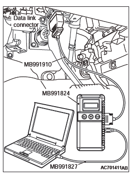
STEP 4. Using scan tool MB991958, check data list.
Check the signals related to the keyless entry system operation.
CAUTION To prevent damage to scan tool MB991958, always turn the ignition switch to the "LOCK" (OFF) position before connecting or disconnecting scan tool MB991958.
- Connect scan tool MB991958. Refer to "How to connect the Scan Tool (M.U.T.-III)".
- Turn the ignition switch to the "ON" position.
- Check the ETACS data list.
- Turn the ignition switch to the LOCK (OFF) position.
- Close the driver's door.
- Close the passenger's door.
- Close the RH-side rear door.
- Close the LH-side rear door.
- Close the liftgate.
- Remove the ignition key from the ignition key cylinder.
- Turn the ignition switch to the "LOCK" (OFF) position.
OK: Normal condition is displayed.
Q: Is the check result normal?
YES (Normal conditions are displayed for all the items.) : Go to Step 5.
NO (Normal condition is not displayed for item No. 254.) : Refer to GROUP 54A, Inspection Procedure 2: ETACS-ECU does not receive any signal from the ignition switch (IG1).
NO (Normal condition is not displayed for item No. 256.) : Refer to GROUP 54A, Inspection Procedure 5: ETACS-ECU does not receive any signal from the front door switch (LH).
NO (Normal condition is not displayed for item No. 257.) : Refer to GROUP 54A, Inspection Procedure 6: ETACS-ECU does not receive any signal from the front door switch (RH).
: Refer to GROUP 54A, Inspection Procedure 8: ETACS-ECU does not receive any signal from the rear door switch (RH).
NO (Normal condition is not displayed for item No. 259.) : Refer to GROUP 54A, Inspection Procedure 7: ETACS-ECU does not receive any signal from the rear door switch (LH).
NO (Normal condition is not displayed for item No. 260.) : Refer to GROUP 54A, Inspection Procedure 9: ETACS-ECU does not receive any signal from the liftgate switch.
NO (Normal condition is not displayed for item No. 264.) : Refer to GROUP 54A, Inspection Procedure 3: ETACS-ECU does not receive any signal from the key reminder switch.
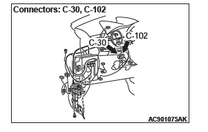
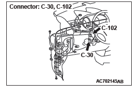
STEP 5. Check KOS-ECU connector C-102 and receiver antenna module connector C-30 for loose, corroded or damaged terminals, or terminals pushed back in the connector.
Q: Are KOS-ECU connector C-102 and receiver antenna module connector C-30 in good condition?
YES : Go to Step 6.
NO : Repair or replace the damaged component(s). Refer to GROUP 00E, Harness Connector Inspection. Check that the keyless entry function works normally.
STEP 6. Check the wiring harness between KOS-ECU connector C-102 (terminal Nos. 7, 9, 10 and 32) and receiver antenna module connector C-30 (terminal Nos. 12, 3, 4 and 8).
Q: Is the wiring harness between KOS-ECU connector C-102 (terminal Nos. 7, 9, 10 and 32) and receiver antenna module connector C-30 (terminal Nos. 12, 3, 4 and 8) in good condition?
YES : Go to Step 7.
NO : The wiring harness may be damaged or the connector(s) may have loose, corroded or damaged terminals, or terminals pushed back in the connector.
Repair the wiring harness as necessary. Check that the keyless entry function works normally.
STEP 7. Check with another registered keyless operation key.
Check that the keyless entry function can be used with another keyless operation key.
Q: Can the keyless entry function be used?
YES : Replace the keyless operation key concerned and register the ID codes.
NO : Go to Step 8.
STEP 8. Check of the troubles
Replace ETACS-ECU. After the replacement, perform the coding, and check that the keyless entry function operates normally.
Q: Is the check result normal?
YES : Intermittent malfunction is suspected.
NO : Replace KOS-ECU and register the ID codes.
Inspection Procedure 13: KOS timer lock function does not work.
CAUTION Before replacing the ECU, ensure that the power supply circuit, the ground circuit and the communication circuit are normal.
OPERATION
After the door is unlocked with the keyless entry function, if no operation is performed, the door is locked when the time specified by a customization function has elapsed. However, an open signal from any door, key reminder switch OFF (with the key inserted) signal, or ignition push switch ON signal has been input to ETACS, the KOS timer will not operate.
PROBABLE CAUSES
- Malfunction of ETACS-ECU
- Malfunction of the door switches
DIAGNOSTIC PROCEDURE
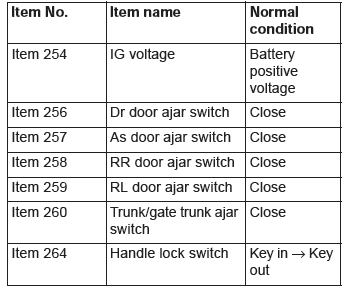
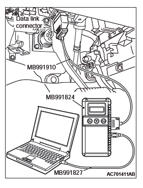
Required Special Tools:
- MB991223: Harness Set
- MB992006: Extra Fine Probe
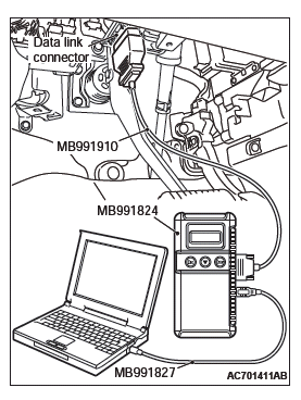
- MB991958: Scan Tool (M.U.T.-III Sub Assembly)
- MB991824: V.C.I.
- MB991827: M.U.T.-III USB Cable
- MB991910: M.U.T.-III Main Harness A
STEP 1. Using scan tool MB991958, read the diagnostic trouble code.
CAUTION To prevent damage to scan tool MB991958, always turn the ignition switch to the "LOCK" (OFF) position before connecting or disconnecting scan tool MB991958.
- Connect scan tool MB991958. Refer to "How to connect scan tool (M.U.T.-III)".
- Turn the ignition switch to the "ON" position.
- Check whether the KOS-ECU related DTC is set.
- Turn the ignition switch to the "LOCK" (OFF) position.
Q: Is the DTC set?
YES : Diagnose the KOS-ECU.
NO : Go to Step 2.
STEP 2. Retest the system.
Check that the KOS timer lock function operates.
Q: Is the check result normal?
YES : Intermittent malfunction.
NO : Perform troubleshooting for each door switch.
Inspection Procedure 14: The dome light, the turn-signal lights and the horn do not operate through the answerback function.
CAUTION Before replacing the ECU, ensure that the power supply circuit, the ground circuit and the communication circuit are normal.
OPERATION
When the keyless entry function is used, the keyless entry hazard answerback function, dome light or horn answerback function operate as set by ETACS customization function. (If the flashing count is set to 0 with a customization function, no answerback function is performed.). If the theft alarm is defective, the keyless entry hazard answerback function may not operate normally.
PROBABLE CAUSES
- Function setting error or no setting with a customization
- Malfunction of the turn signal light
- Malfunction of the dome light
- Malfunction of the horn
- Malfunction of the theft alarm sensor
- Malfunction of the theft alarm siren
- Malfunction of ETACS-ECU
DIAGNOSTIC PROCEDURE
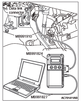
Required Special Tools:
- MB991223: Harness Set
- MB992006: Extra Fine Probe
- MB991958: Scan Tool (M.U.T.-III Sub Assembly)
- MB991824: V.C.I.
- MB991827: M.U.T.-III USB Cable
- MB991910: M.U.T.-III Main Harness A
STEP 1. Verify the hazard warning lights.
Check that the hazard warning lights illuminate normally.
Q: Is the check result normal?
YES : Go to Step 2.
NO : Refer to GROUP 54A, Inspection Procedure 1: The Hazard Warning lights does not Illuminate.
STEP 2. Verify the dome light.
Check that the dome light illuminate normally.
Q: Is the check result normal?
YES : Go to Step 3.
NO : Refer to GROUP 54A, Trouble Symptom Chart.
STEP 3. Verify the horn.
Check that the horn normally.
Q: Is the check result normal?
YES : Go to Step 4.
NO : Replace the horn.
STEP 4. Check the customize function.
Check that any one of the followings other than "Lock: 0, Unlock: 0" is set for "Hazard answerback" with a customization function.
- Lock:1, Unlock:2
- Lock:1, Unlock:0
- Lock:0, Unlock:2
- Lock:2, Unlock:1
- Lock:2, Unlock:0
- Lock:0, Unlock:1
Q: Is the check result normal?
YES : Go to Step 5.
NO : Set "Hazard answerback" to any one other than "Lock: 0, Unlock: 0" with a customization function.
STEP 5. Check the customize function.
Check that any one of the followings other than "Not sound horn" is set for "Horn chirp by RKE" with a customization function.
- Lock any time
- W lock any time
Q: Is the check result normal?
YES : Go to Step 6.
NO : Set "Horn chirp by RKE" to any one other than "Not sound horn" with a customization function.
STEP 6. Using scan tool MB991958, read the diagnostic trouble code.
CAUTION To prevent damage to scan tool MB991958, always turn the ignition switch to the "LOCK" (OFF) position before connecting or disconnecting scan tool MB991958.
- Connect scan tool MB991958. Refer to "How to connect scan tool (M.U.T.-III)".
- Turn the ignition switch to the "ON" position.
- Check whether the theft alarm related DTC is set.
- Turn the ignition switch to the "LOCK" (OFF) position.
Q: Is the DTC set?
YES : Diagnose the theft alarm.
NO : Go to Step 7.
STEP 7. Using scan tool MB991958, read the diagnostic trouble code.
CAUTION To prevent damage to scan tool MB991958, always turn the ignition switch to the "LOCK" (OFF) position before connecting or disconnecting scan tool MB991958.
- Connect scan tool MB991958. Refer to "How to connect scan tool (M.U.T.-III)".
- Turn the ignition switch to the "ON" position.
- Check whether the KOS-ECU related DTC is set.
- Turn the ignition switch to the "LOCK" (OFF) position.
Q: Is the DTC set?
YES : Diagnose the KOS-ECU. NO : Go to Step 8.
STEP 8. Check of the troubles
Check if the keyless entry hazard answerback, doom light answerback and horn answerback function works normally.
Q: Is the check result normal?
YES : Intermittent malfunction.
NO : Replace ETACS-ECU.
Inspection Procedure 15: Outer tone alarm does not sound.
CAUTION Before replacing the ECU, ensure that the power supply circuit, the ground circuit and the communication circuit are normal.
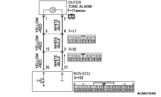
Outer Tone Alarm Circuit
OPERATION
- The outer tone alarm sounds under the following conditions.
- When the door is locked or unlocked with the keyless or keyless operation function
- Door lock does not operate.
- The keyless operation key is brought out of the vehicle.
- Also, with a customization function, "Tone alarm answerback" may be set to "Not Sound Tone alarm".
PROBABLE CAUSES
- Malfunction of the antenna and outer tone alarm assembly
- Malfunction of the KOS-ECU
- Malfunction of the connector
- Function setting error or no setting with a customization
DIAGNOSTIC PROCEDURE
STEP 1. Using scan tool MB991958, read the diagnostic trouble code.
CAUTION To prevent damage to scan tool MB991958, always turn the ignition switch to the "LOCK" (OFF) position before connecting or disconnecting scan tool MB991958.
- Connect scan tool MB991958. Refer to "How to connect scan tool (M.U.T.-III)".
- Turn the ignition switch to the "ON" position.
- Check whether the KOS-ECU related DTC is set.
- Turn the ignition switch to the "LOCK" (OFF) position.
Q: Is the DTC set?
YES : Diagnose the KOS-ECU.
NO : Go to Step 2.
STEP 2. Check the customize function.
Check that either of the followings other than "Not sound tone alarm" is set for "Tone alarm answer back" with the customization function.
- At keyless key
- At keyless
- At Both
Q: Is the check result normal?
YES : Go to Step 3.
NO : Set either of the followings other than "Not sound tone alarm" for "Tone alarm answer back" with the customization function.
STEP 3. Using scan tool MB991958, read the actuator test.
CAUTION To prevent damage to scan tool MB991958, always turn the ignition switch to the "LOCK" (OFF) position before connecting or disconnecting scan tool MB991958.
- Connect scan tool MB991958. Refer to "How to connect scan tool (M.U.T.-III)".
- Turn the ignition switch to the "ON" position.
- Check that the outer tone alarm sounds.
- Turn the ignition switch to the "LOCK" (OFF) position.
Q: Is the DTC set?
YES : Go to Step 6.
NO : Go to Step 4.
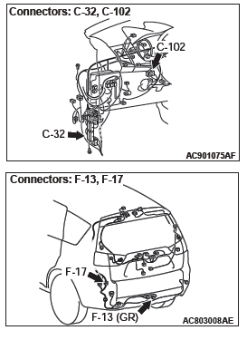
STEP 4. Check KOS-ECU connector C-102 and outer tone alarm connector F-13 for loose, corroded or damaged terminals, or terminals pushed back in the connector.
Q: Are KOS-ECU connector C-102 and outer tone alarm connector F-13 in good condition?
YES : Go to Step 5.
NO : Repair or replace the damaged component(s). Refer to GROUP 00E, Harness Connector Inspection. Check that the outer tone alarm works normally.
STEP 5. Check the wiring harness between KOS-ECU connector C-102 (terminal Nos. 35 and 37) and outer tone alarm connector F-13 (terminal Nos. 1 and 2).
Check the power supply and ground lines for open circuit.
NOTE: Also check intermediate connector C-32 and F-17 for loose, corroded, or damaged terminals, or terminals pushed back in the connector. If intermediate connector C-32 and F-17 is damaged, repair or replace the damaged component(s) as described in GROUP 00E, Harness Connector Inspection.
Q: Is the wiring harness between KOS-ECU connector C-102 (terminal Nos. 35 and 37) and outer tone alarm connector F-13 (terminal Nos. 1 and 2) in good condition?
YES : Go to Step 6.
NO : The wiring harness may be damaged or the connector(s) may have loose, corroded or damaged terminals, or terminals pushed back in the connector.
Repair the wiring harness as necessary. Check that the outer tone alarm works normally.
STEP 6. Check of the troubles
Check that the outer tone alarm sounds when the outer tone alarm sounding conditions are met.
Q: Is the check result normal?
YES : Intermittent malfunction is suspected. NO : Replace KOS-ECU and register the ID codes.
Inspection Procedure 16: The keyless operation key cannot be registered using scan tool.
CAUTION When replacing the ECU, always check that the communication circuit is normal.
Receiver Antenna Module and KOS-ECU Circuit
TECHNICAL DESCRIPTION (COMMENT)
If only some keyless operation keys cannot be registered, the keyless operation key itself may be faulty.
If no keyless operation key can be registered, the key assembly may have already been registered for another vehicle, or the KOS-ECU may be faulty.
TROUBLESHOOTING HINTS
- Insufficient inverse insertion of keyless operation key at the emergency operation
- Malfunction of the keyless operation key
- Damaged wiring harness and connectors
- Malfunction of receiver antenna module
- Malfunction of KOS-ECU
- Ignition key registered for other vehicle
DIAGNOSIS
Required Special Tools:
- MB991958: Scan Tool (M.U.T.-III Sub Assembly)
- MB991824: Vehicle Communication Interface (V.C.I.)
- MB991827: M.U.T.-III USB Cable
- MB991910: M.U.T.-III Main Harness A (Vehicles with CAN communication system)
STEP 1. Sufficiently insert the keyless operation key in the inverted direction at the emergency operation, and check the trouble symptom.
With the emergency operation by the sufficient inverse insertion of keyless operation key, check if the key can be registered.
Q: Is the check result normal?
YES : The procedure is complete.
NO : Go to Step 2.
STEP 2. Check the keyless operation key inserted in the key cylinder for interference.
Q: Are there other keyless operation keys or anything that interferes with the communication (things that generate radio waves such as magnets and an air-cleaning device that has a power plug) near the keyless operation key inserted in the key cylinder?
YES : Move away or remove other keyless operation keys or things that interfere with the communication (things that generate radio waves such as magnets and a air-cleaning device that has a power plug) near the keyless operation key. Then, go to step 3.
NO : Go to Step 4.
STEP 3. Retest the system
Check that the keyless operation key can be registered.
Q: Is the keyless operation key that cannot be registered using scan tool?
YES : Go to Step 4.
NO : The procedure is complete.
STEP 4. Check which keyless operation key cannot be registered.
Q: Can any one of the keyless operation keys be registered?
YES (Only some keys) : Replace the key that cannot be registered and register the ID codes. After registering the ID codes, go to Step 6.
NO (All keys) : Go to Step 5.
STEP 5. Retest the system
Check the scan tool screen when the key was not able to be registered.
Q: Is the error message of scan tool screen "Abnormality in key" ?
YES (Abnormality in key) : Carry out DTC B1A25: Key ID unmatched and DTC B1A35: Transponder read error.
Then, go to Step 7.
NO (ECU internal error) : Replace KOS-ECU and register the ID codes.
STEP 6. Retest the system
Check that the keyless operation key can be registered.
Q: Is the keyless operation key that cannot be registered using scan tool?
YES : Replace KOS-ECU and register the ID codes.
NO : The procedure is complete.
STEP 7. Retest the system Check that the keyless operation key can be registered.
Q: Is the keyless operation key that cannot be registered using scan tool?
YES : Go to Step 8.
NO : The procedure is complete.
STEP 8. Check receiver antenna module connector C-30 and KOS-ECU connector C-102 for loose, corroded or damaged terminals, or terminals pushed back in the connector.
Q: Is the receiver antenna module connector C-30 and KOS-ECU connector C-102 in good condition?
YES : Go to Step 9.
NO : Repair the defective connector.
STEP 9. Check the wiring harness between the receiver antenna module connector C-30 (terminal Nos.1, 8, 12, 3, 5, 2, 4) and the KOS-ECU connector C-102 (terminal Nos.12, 32, 7, 9, 13, 11, 10).
Check the all harness lines for open circuit and short circuit.
Q: Is the wiring harness between receiver antenna module connector C-30 (terminal Nos.1, 8, 12, 3, 5, 2, 4) and the KOS-ECU connector C-102 (terminal Nos.12, 32, 7, 9, 13, 11, 10) in good condition?
YES : Go to Step 10.
NO : Repair the wiring harness.
STEP 10. Replace the receiver antenna module, and retest the system.
Check that the keyless operation key can be registered.
Q: Is the keyless operation key that cannot be registered using scan tool?
YES : Replace KOS-ECU and register the ID codes.
NO : The procedure is complete.
Inspection Procedure 17: Engine does not start with emergency key (cranking but no initial combustion).
TECHNICAL DESCRIPTION (COMMENT)
If the fuel injection does not work, KOS-ECU and the MFI system may have a problem. This symptom is not considered abnormal when the engine is started by an keyless operation key that has not been registered.
TROUBLESHOOTING HINTS
- Malfunction of the MFI system
- Malfunction of KOS-ECU
- Malfunction of CAN bus line
- Malfunction of the transponder
- VIN not programmed
DIAGNOSIS
Required Special Tools:
- MB991958: Scan Tool (M.U.T.-III Sub Assembly)
- MB991824: Vehicle Communication Interface (V.C.I.)
- MB991827: M.U.T.-III USB Cable
- MB991910: M.U.T.-III Main Harness A (Vehicles with CAN communication system)
STEP 1. Check the battery voltage.
Measure the battery voltage when cranking.
- The voltage should measure 8 volt or more.
Q: Is the measured voltage 8 volt or more?
YES : Go to Step 2.
NO : Check the battery.
STEP 2. Using scan tool MB991958, diagnose the CAN bus line.
CAUTION To prevent damage to scan tool MB991958, always turn the ignition switch to the "LOCK" (OFF) position before connecting or disconnecting scan tool MB991958.
- Connect scan tool MB991958. Refer to "How to connect the Scan Tool (M.U.T.-III)".
- Turn the ignition switch to the "ON" position.
- Diagnose the CAN bus line.
- Turn the ignition switch to the "LOCK" (OFF) position.
Q: Is the CAN bus line found to be normal?
YES : Go to Step 3.
NO : Repair the CAN bus line.
STEP 3. Using scan tool MB991958, read the MFI system diagnostic trouble code.
Check if DTC is set to the engine control module.
Q: Is the DTC set?
YES : Troubleshoot the MFI system.
NO : Go to Step 4.
STEP 4. Using scan tool MB991958, read the KOS-ECU diagnostic trouble code.
Check if DTC is set to the KOS.
Q: Is the DTC set?
YES : Refer to P.42B.
NO : Go to Step 5.
STEP 5. Check that the engine starts.
Q: Does the engine start?
YES : The procedure is complete.
NO : Refer to GROUP 13A , Diagnosis <2.4L Engine> or GROUP 13B , Diagnosis <3.0L Engine>. When the cause of the failure cannot be tracked down by the troubleshooting in GROUP 13A <2.4L Engine> or GROUP 13B <3.0L Engine>, replace KOS-ECU and register the ID codes.
Inspection Procedure 18: Power door locks with selective unlocking does not work.
CAUTION Before replacing the ECU, ensure that the power supply circuit, the ground circuit and the communication circuit are normal.
COMMENT ON TROUBLE SYMPTOM
When the keyless entry function and door entry function operate normally, but there is an error to only the power door locks with selective unlocking, ETACS-ECU may have a problem. In addition, it is possible that the function has been set to "all doors unlock" by the customization function.
PROBABLE CAUSES
- Malfunction of ETACS-ECU
- Damaged wiring harness and connectors
DIAGNOSIS
STEP 1. Check the customization
Q: Are the power door locks with selective unlocking enabled by the customization function?
YES : Go to Step 2
NO : Set the power door locks with selective unlocking to "Enabled" by using the customization function.
STEP 2. Power door locks with selective unlocking operation check
Check that the power door locks with selective unlocking operate normally by means of the keyless entry function or door entry function.
Q: Is the check result normal?
YES : Go to Step 5
NO (Does not work by means of keyless entry function) : Go to Step 3
NO (Does not work by means of door entry function) : Go to Step 4
NO (Does not work by means of either functions) : Go to Step 5
STEP 3. Keyless entry system operation check
Press the unlock switch of the keyless operation key and check that only the driver's door is unlocked. Then, press the unlock switch once again within 2 seconds after that to check that the front passenger's door, rear doors, and liftgate are unlocked.
Q: Does the keyless entry function work normally?
YES : Go to Step 5
NO (Only the driver's door is not unlocked.) : Replace ETACS-ECU.
NO (The driver's door, front passenger's door, rear doors, and tailgate are not unlocked.) : Refer to Inspection Procedure 12: "Keyless entry function does not work.
STEP 4. Door entry function operation check
Press the lock/unlock switch (driver's side) and check that only the driver's door is unlocked. Then, press the lock/unlock switch (driver's side) once again within 2 seconds after that to check that the front passenger's door, rear doors, and liftgate are unlocked.
Q: Does the door entry function work normally?
YES : Go to Step 5
NO (Only the driver's door is not unlocked.) : Replace ETACS-ECU.
NO (The driver's door, front passenger's door, rear doors, and tailgate are not unlocked.) : Refer to Inspection Procedure 7: "Driver's door lock/unlock switch does not work".
STEP 5. Check of the troubles
Check that the power door locks with selective unlocking works normally.
Q: Is the check result normal?
YES : Intermittent malfunction.
NO : Replace ETACS-ECU.
DATA LIST REFERENCE TABLE
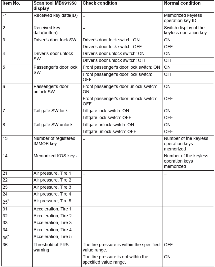
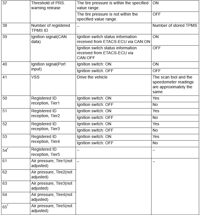
NOTE: * shows that it is displayed but not used.
ACTUATOR TEST TABLE

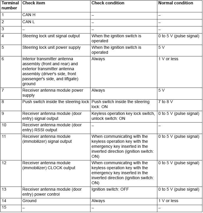
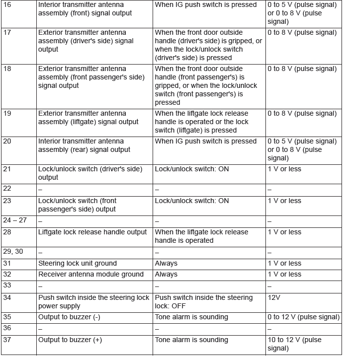
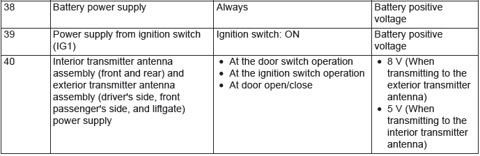
TERMINAL VOLTAGE REFERENCE CHART
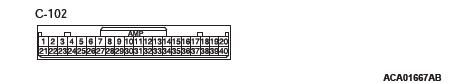
KOS-ECU TERMINAL CHECK
READ NEXT:
 On-vehicle Service
ID CODES REGISTRATION PROCEDURE
REGISTRATION USING SCAN TOOL MB991958 (M.U.T.-III SUB ASSEMBLY)
Required Special Tools:
MB991958 Scan Tool (M.U.T.-III Sub Assembly)
MB991824: Vehicle Communication
KOS-ECU, Keyless Operation Key, TPMS Transmitter
KOS-ECU
REMOVAL AND INSTALLATION
CAUTION
If KOS-ECU is replaced, refer to ID code registration
need judgment table P.42B to complete
the registration of each ID code.
Removal
KOS-ECU
Exterior Tra
Wireless Control Module (WCM)
General Information
The wireless control module (WCM) is a system that
integrates the keyless entry function, with which
remote operation (opening/closing of all doors and
the liftgate and operation o
SEE MORE:
Windshield Wiper, Windshield Washer
WINDSHIELD WIPER
REMOVAL AND INSTALLATION
Wiper blade removal steps
Wiper blade assembly
Wiper blade
Windshield wiper motor and link
assembly removal steps
Wiper arm and blade assembly
Hood weatherstrip rear
Front deck garnish
Windshield wiper link
Wiper motor link plate
Windshield wiper
Intake and Exhaust
Service Specifications
Special Tools
Intake and Exhaust
Diagnosis
INTRODUCTION
Intake leaks usually create driveability issues that
are not obviously related to the intake system.
Exhaust leaks or abnormal noise is caused by
cracks, gaskets and fittings, or by exhaust pipe or
muffler damage due
