Mitsubishi Outlander: How To Use Troubleshooting, Inspection Service Points
TROUBLESHOOTING CONTENTS
DANGER
The SRS-ECU adopts the rollover specification that the curtain airbag and seat belt pre-tensioner operate at the occurrence of rollover. Therefore, do not tilt the vehicle to the right and left with the IG ON or tilt the SRS-ECU to the right and left with the IG ON and the harness installed.
CAUTION
During diagnosis, a diagnostic trouble code associated with other system may be set when the ignition switch is turned "ON" with connector( s) disconnected. On completion, confirm all systems for diagnostic trouble code(s). If diagnostic trouble code(s) are set, erase them all.
WARNING
Since the radiator fan rotates during CAN bus line diagnostics, make sure that no one is servicing the engine compartment before diagnosing the CAN bus line. Since the CAN communication stops when diagnosing the CAN bus line, the ETACS-ECU detects the time-out of the engine control module, and activates the radiator fan to prevent overheating as fail-safe.
Troubleshooting of electronic control systems for which scan tool MB991958 can be used follows the basic outline described below. Even in systems for which scan tool MB991958 cannot be used, some of these systems still follow this outline.
1. STANDARD FLOW OF DIAGNOSTIC TROUBLESHOOTING
Troubleshooting sections are based on the diagnostic flow as below. If the diagnostic flow is different from that given below, or if additional explanation is required, the details of such differences or additions will also be listed.
Diagnostic method
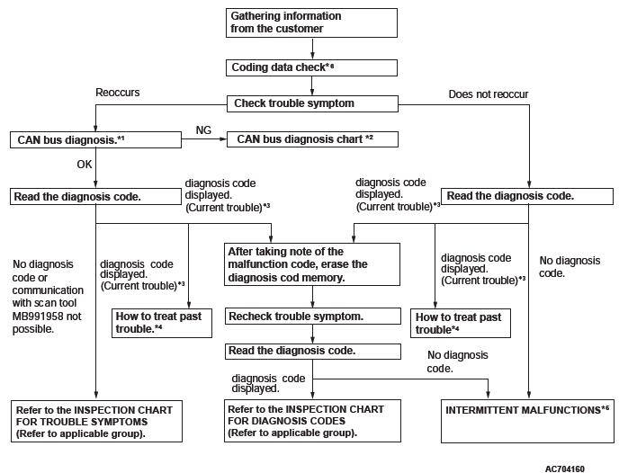
*1: For how to diagnose CAN bus lines.
*2: For the CAN bus diagnosis chart.
*3: When scan tool MB991958 detects a diagnostic
trouble code, its display informs users whether
a mechanical problem currently exists or whether
it existed before. The message for the former
state identifies it as an "Active" and the message
for the latter identifies it as a "Stored".
*4: For how to treat past trouble.
*5: For how to cope with intermittent malfunctions.
*6: For coding data.
2. SYSTEM OPERATION AND SYMPTOM VERIFICATION TESTS
If verification of the symptom(s) is difficult, procedures for checking operation and verifying symptoms are shown.
3. DIAGNOSTIC FUNCTION
The following trouble code diagnosis are shown.
- How to read diagnostic trouble codes
- How to erase diagnostic trouble codes
- Input inspection service points
4. DIAGNOSTIC TROUBLE CODE CHART
If the scan tool displays a diagnostic trouble code, find the applicable inspection procedure according to this chart.
5. SYMPTOM CHART
If there are symptoms, even though the scan tools show that no DTCs are set, inspection procedures for each symptom will be found by using this chart.
6. DIAGNOSTIC TROUBLE CODE PROCEDURES
Indicates the inspection procedures corresponding to each diagnostic trouble code.
7. SYMPTOM PROCEDURES
Indicates the inspection procedures corresponding to each symptom listed in the Symptom Chart.
8. SERVICE DATA REFERENCE TABLE
Inspection items and normal judgment values have been provided in this chart as reference information.
9. CHECK AT ECU TERMINALS
Terminal numbers for the ECU connectors, inspection items, and standard values have been provided in this chart as reference information.
TERMINAL VOLTAGE CHECKS
1. Connect a needle-nosed wire probe to a voltmeter probe.
CAUTION Short-circuiting the positive (+) probe between a connector terminal and ground could damage the vehicle wiring, the sensor, the ECU, or all three. Use care to prevent this!
2. Insert the needle-nosed wire probe into each of the ECU connector terminals from the wire side, and measure the voltage while referring to the check chart.
NOTE: Measure voltage with the ECU connectors connected.
You may find it convenient to pull out the ECU to make it easier to reach the connector terminals.
Checks don't have to be carried out in the order given in the chart.
3. If voltage readings differ from normal condition values, check related sensors, actuators, and wiring. Replace or repair as needed.
4. After repair or replacement, recheck with the voltmeter to confirm that the repair has corrected the problem.
TERMINAL RESISTANCE AND CONTINUITY CHECKS
1. Turn the ignition switch to the "LOCK" (OFF) position.
2. Disconnect the ECU connector.
CAUTION If resistance and continuity checks are performed on the wrong terminals, damage to the vehicle wiring, sensors, ECU, and/or ohmmeter may occur. Use care to prevent this!
3. Measure the resistance and check for continuity between the terminals of the ECU harness-side connector while referring to the check chart.
NOTE: Checks don't have to be carried out in the order given in the chart.
4. If the ohmmeter shows any deviation from the Normal Condition value, check the corresponding sensor, actuator and related electrical wiring, then repair or replace.
5. After repair or replacement, recheck with the ohmmeter to confirm that the repair has corrected the problem.
10. INSPECTION PROCEDURES USING AN OSCILLOSCOPE
When there are inspection procedures using an oscilloscope, these are listed.
HOW TO USE THE INSPECTION PROCEDURES
The causes of many of the problems occurring in electric circuitry are generally the connectors, components, the ECU, and the harnesses between connectors, in that order. These inspection procedures follow this order. They first try to discover a problem with a connector or a defective component.
HARNESS INSPECTION
Check for an open or short circuit in the harness between the terminals which were faulty according to the connector measurements. Carry out this inspection while referring to GROUP 00E, Harness Connector Inspection. Here, "Check harness between power supply and terminal xx" also includes checking for blown fuse. For inspection service points when there is a blown fuse, refer to "Inspection Service Points for a Blown Fuse.
MEASURES TO TAKE AFTER REPLACING THE ECU
If the trouble symptoms have not disappeared even after replacing the ECU, repeat the inspection procedure from the beginning.
CONNECTOR MEASUREMENT SERVICE POINTS
Turn the ignition switch to the "LOCK" (OFF) position when connecting and disconnecting the connectors. Turn the ignition switch to "ON" when measuring, unless there are instructions to the contrary.
IF INSPECTING WITH THE CONNECTOR CONNECTED WATERPROOF CONNECTORS
Be sure to use special tool. Never insert a test probe from the harness side, as this will reduce the waterproof performance and result in corrosion.
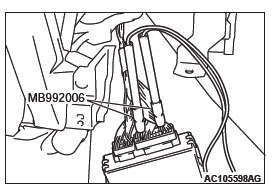
IF INSPECTING WITH THE CONNECTOR CONNECTED ORDINARY (NON-WATERPROOF) CONNECTORS
Required Special Tool:
- MB992006: Extra Fine Probe
Inspect by inserting a test probe from the harness side. If the connector is too small to insert a test probe (e.g. control unit connector), do not insert it forcibly. Use special tool MB992006 (extra fine probe).
IF INSPECTING WITH THE CONNECTOR DISCONNECTED
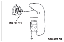
When Inspecting a Female Pin
- From front side of the connector
Required Special Tool:
MB991219: Inspection Harness (Included in MB991223, Harness Set)
The inspection harness for connector pin contact pressure should be used. The test probe should never be forcibly inserted, as it may cause a defective contact.
- From back side of the connector (SRS-ECU harness side connector)
Since the SRS-ECU harness connector is plated to improve conductivity, observe the warning below when checking this connector.
WARNING Insert the backprobing tool into the connector from the harness side, and connect the tester to the backprobing tool. If any tool other than the backprobing tool is used, it may cause damage to the harness and other components. Furthermore, measurement should not be carried out by touching the backprobing tool directly against the terminals from the front of the connector. The terminals are plated to increase their conductivity, so that if they are touched directly by the backprobing tool, the plating may break, which will decrease reliability.
When Inspecting a Male Pin
CAUTION At this time, be careful not to short the connector pins with the test probes. Doing so may damage the circuits inside the ECU.
Touch the pin directly with the test probe.
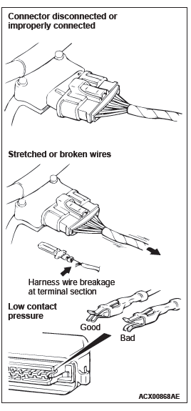
CONNECTOR INSPECTION SERVICE POINTS
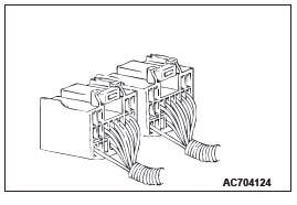
VISUAL INSPECTION
- Connector is disconnected or improperly connected
- Connector pins are pulled out
- Stretched an broken wires at terminal section
- Low contact pressure between male and female terminals
- Low connection pressure due to rusted terminals or foreign matter lodged in terminals
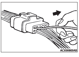
CONNECTOR PIN INSPECTION
If the connector pin stopper is damaged, the terminal connections (male and female pins) will not be perfect even when the connector body is connected, because the pins may pull out of the back side of the connector. Therefore, gently pull the wires one by one to make sure that no pins pull out of the connector.
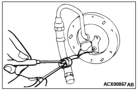
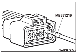
CONNECTOR ENGAGEMENT INSPECTION
Required Special Tool:
MB991219: Inspection Harness (contained in MB991223 Test Harness)
Use special tool, MB991219 to inspect the engagement of the male pins and female pins. [Pin drawing force: 1 N (0.2 pound) or more]
HOW TO COPE WITH INTERMITTENT MALFUNCTIONS
Most intermittent malfunctions occur under certain conditions. If those conditions can be identified, the cause will be easier to find.
TO COPE WITH INTERMITTENT MALFUNCTION;
1. ASK THE CUSTOMER ABOUT THE MALFUNCTION
Ask what it feels like, what it sounds like, etc. Then ask about driving conditions, weather, frequency of occurrence, and so on.
2. DETERMINE THE CONDITIONS FROM THE CUSTOMER'S RESPONSES
Typically, almost all intermittent malfunctions occur from conditions like vibration, temperature and/or moisture change, poor connections. From the customer's responses, it should be reasoned which condition is most likely.
3. USE SIMULATION TEST
Use the simulation tests below to attempt to duplicate the customer's complaint. Determine the most likely circuit(s) and perform the simulation tests on the connectors and parts of that circuit(s). Be sure to use the inspection procedures provided for diagnostic trouble codes and trouble symptoms.
For temperature and/or moisture condition related intermittent malfunctions, try to change the conditions of the suspected circuit components, then use the simulation tests below.
4. VERIFY THE INTERMITTENT MALFUNCTION IS ELIMINATED
Repair the malfunctioning part and try to duplicate the condition( s) again to verify the intermittent malfunction has been eliminated.
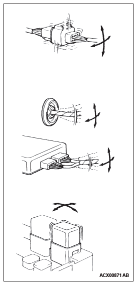
SIMULATION TESTS
NOTE: In case of difficulty in finding the cause of the intermittent malfunction, the data recorder function in the scan tool is effective.
For these simulation tests, shake, then gently bend, pull, and twist the wiring of each of these examples to duplicate the intermittent malfunction.
- Shake the connector up-and-down, and right-and-left.
- Shake the wiring harness up-and-down, and right-and-left.
Especially, check the splice points of wiring harnesses carefully.
- Shake the part or sensor.
HOW TO TREAT PAST TROUBLE
Since the trouble may still be present even the status is "Stored", set the vehicle to the diagnostic trouble code detection condition and check that the status changes to "Active". If the status does not change from "Stored", carry out the following procedure.
1. Establish from the customer whether a fuse or connector has been replaced or disconnected.
2. If yes, erase the diagnostic trouble code, and then check that no diagnostic code is reset. If no diagnostic trouble code is reset, the diagnosis is complete.
3. If no, follow the applicable Diagnostic Trouble Code Chart. Then check the wiring harness and connector, and refer to "How to Cope with Intermittent Malfunction".
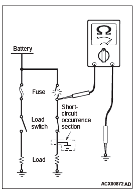
INSPECTION SERVICE POINTS FOR A BLOWN FUSE
Remove the blown fuse and measure the resistance between the load side of the blown fuse and the ground. Close the switches of all circuits which are connected to this fuse. If the resistance is almost 0 Ω at this time, there is a short somewhere between these switches and the load. If the resistance is not 0 Ω, there is no short at the present time, but a momentary short has probably caused the fuse to blow.
The main causes of a short circuit are the following.
- Harness being clamped by the vehicle body
- Damage to the outer casing of the harness due to wear or heat
- Water getting into the connector or circuitry
- Human error (mistakenly shorting a circuit, etc.)
READ NEXT:
 Vehicle Identification, General Data and Specifications
Vehicle Identification
VEHICLE IDENTIFICATION NUMBER PLATE
VEHICLES IDENTIFICATION NUMBER LOCATION
The vehicle identification number (VIN) plate is located on a
plate attached to the left top side of
Precautions Before Service
CAUTIONS FOR WORKING IN ENGINE
COMPARTMENT
WARNING
Just after the ignition switch is turned to "LOCK"
(OFF) position, the adjustments must always be made
with the cooling fan stopped. After the igniti
Tightening Torque, Lubrication and Maintenance
Tightening Torque
Each torque value in the table is a standard value for
tightening under the following conditions.
1. Bolts, nuts and washers are all made of steel and
plated with zinc.
2. The threa
SEE MORE:
Service precautions
Adequate care of your vehicle at regular intervals serves to preserve the value
and appearance as long as possible.
Maintenance items as described in this owner’s manual can be performed by the
owner.
We recommend you to have the periodic inspection and maintenance performed by
a MITSUBISH
How To Diagnose (Electrical)
HOW TO DIAGNOSE
The most important point in troubleshooting is to
determine "Probable Cause". Once the probable
causes are determined, parts to be checked can be
limited to those associated with such probable
causes. The determination of the probable causes
must be based on a theory and be supported
