Mitsubishi Outlander: Precautions Before Service
CAUTIONS FOR WORKING IN ENGINE COMPARTMENT
WARNING
Just after the ignition switch is turned to "LOCK" (OFF) position, the adjustments must always be made with the cooling fan stopped. After the ignition switch is turned to "LOCK" (OFF) position, the cooling fun might be driven for a few minutes by the after run fan control. If the adjustments are made with the cooling fun driven, injury or damage may occur.
SUPPLEMENTAL RESTRAINT SYSTEM (SRS)
1. Items to review when servicing SRS:
- Be sure to read GROUP 52B, Supplemental Restraint System (SRS). For safe operation, please follow the directions and heed all warnings.
- Wait at least 60 seconds after disconnecting the battery cable before doing any further work. The SRS system is designed to retain enough voltage to deploy the air bag even after the battery has been disconnected. Serious injury may result from unintended air bag deployment if work is done on the SRS system immediately after the battery cable is disconnected.
- Warning labels must be heeded when servicing or handling SRS components. Warning labels can be found in the following locations (Refer to GROUP 52B, Warning/Caution Labels).
- Always use the designated special tools and test equipment.
- Store components removed from the SRS in a clean and dry place. The air bag module should be stored on a flat surface and placed so that the pad surface is facing upward.
- Never attempt to disassemble or repair the SRS components (SRS-ECU, air bag module and clock spring). If there is a defect, replace the defective part.
- Whenever you finish servicing the SRS, check the SRS warning light operation to make sure that the system functions properly.
- Be sure to deploy the air bag before disposing of the air bag module or disposing of a vehicle equipped with an air bag.
2. Observe the following when carrying out operations on places where SRS components are installed, including operations not directly related to the SRS air bag.
- When removing or installing parts, do not allow any impact or shock to occur to the SRS components.
- If heat damage may occur during paint work, remove the SRS-ECU, the air bag module, clock spring, the front impact sensor, the side impact sensor, and the seat belt pre-tensioner.
- SRS-ECU, air bag module, clock spring, front impact sensor, the side impact sensor: 93 ºC (200 ºF) or more
- Seat belt pre-tensioner: 90 ºC (194 ºF) or more
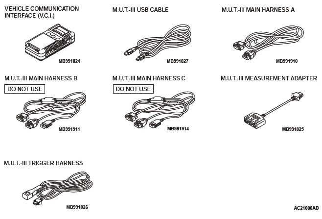
SCAN TOOL (MULTI USE TESTER { M.U.T.-III } SUB ASSEMBLY)
CAUTION
Turn the ignition switch to the "LOCK" (OFF) position before disconnecting or connecting the scan tool.
NOTE: M.U.T.-III trigger harness is not necessary when pushing V.C.I. ENTER key.
HOW TO PERFORM VEHICLE IDENTIFICATION NUMBER (VIN) WRITING
CAUTION
The F.A.S.T-Key (Free-hand Advanced Security Transmitter) is described as the Keyless Operation System (KOS) in this manual. (KOS is indicated as F.A.S.T. in the scan tool display.)
Follow the procedure below to register the VIN of the Wireless Control Module (WCM) and the Keyless Operation System (KOS).
The VIN is stored in the engine control module (ECM), WCM, and the KOS-ECU. If the VIN is improperly erased, the engine warning light or the keyless operation system warning indicator illuminate, and the diagnostic trouble code is displayed.
When the ECM, WCM, and the KOS-ECU are replaced, follow the procedure below to write the VIN.
Screen flow of scan tool (M.U.T.- III)
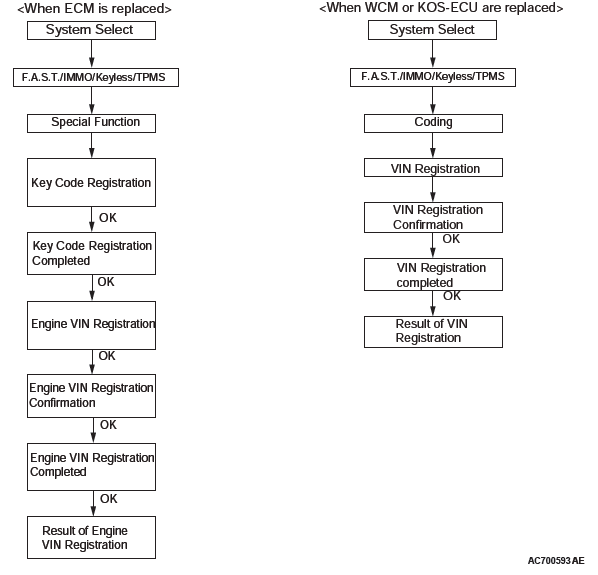
WRITING PROCEDURE
Required Special Tools:
- MB991958: Scan Tool (M.U.T.-III Sub Assembly)
- MB991824: V.C.I.
- MB991827: M.U.T.-III USB Cable
- MB991910: M.U.T.-III Main Harness A
CAUTION
Check that diagnostic trouble code P0603 "EEPROM fail" is not set. When diagnostic trouble code P0603 "EEPROM fail" is set, the ECM cannot store the key code even if the key code is registered. If this diagnostic trouble code is set, troubleshoot the ECM and repair. Then register the key code to the ECM.
CAUTION
Before connecting or disconnecting the MB991958: Scan Tool, turn the ignition switch to the "LOCK" (OFF) position.
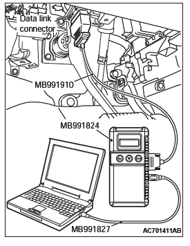
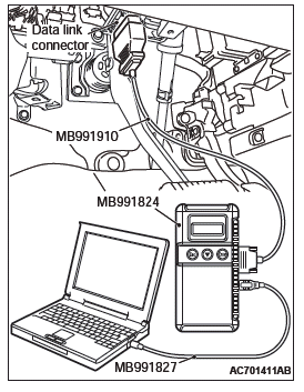
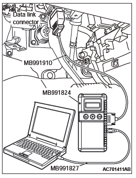
Connect scan tool MB991958 to the 16-pin data link connector as follows.
NOTE: For details on how to use scan tool MB991958, refer to the "M.U.T.-III Owner's Manual".
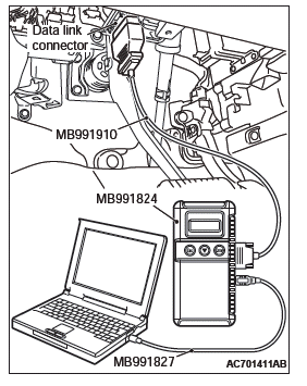
1. Ensure that the ignition switch is at the "LOCK" (OFF) position.
2. Start up the personal computer.
3. Connect special tool MB991827 to special tool MB991824 and the personal computer.
4. Connect special tool MB991910 to the special tool MB991824.
5. Connect special tool MB991910 to the data link connector of the vehicle.
6. Turn the special tool MB991824 power switch to the "ON" position.
NOTE: When the special tool MB991824 is energized, the special tool MB991824 indicator light will be illuminated in a green color.
7. Start the "M.U.T.-III system" on the personal computer and turn the ignition switch to the "ON" position.
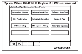
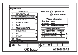
8. Select "F.A.S.T./IMMO/Keyless/TPMS" button from the "System Select" screen. Then, select the applicable option code item and push the OK button.
9. Select "Special Function" on the next screen.
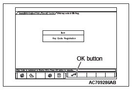
10.Select "ENG key code & VIN Reg." from the "Special Function" screen.
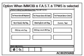
11.Push the OK button after "ENG key code & VIN Reg." is displayed.
12.Push the OK button after "Completed. Press the OK button and move to VIN writing function" is displayed.
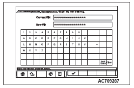
13.Enter the VIN of registering vehicle and push the OK button.
14.Push the OK button after "VIN Writing will start. Are you sure?" is displayed.
15.Return to the previous screen and "In Progress" is displayed at the lower-left corner on the screen.
16.Push the OK button after "Completed" is displayed.
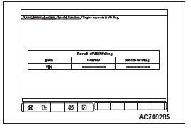
17.VIN writing result is displayed.
18.Complete the scan tool MB991958.
19.Disconnecting the scan tool MB991958 is the reverse of the connecting sequence, making sure that the ignition switch is at the "LOCK" (OFF).
20.Push the OK button after "Completed" is displayed.
21.Terminate the scan tool MB991958.
22.Turn the ignition switch to the "LOCK" (OFF) position and then disconnect scan tool MB991958.
VIN WRITING STEPS FOR WCM AND KOS-ECU
CAUTION
Before the VIN registration to WCM and KOS-ECU, check that the VIN of ECM and vehicle are matched.
CAUTION
Check that diagnostic trouble code B2416 "ECU internal error" is not set. When diagnostic trouble code B2416 "ECU internal error" is set, the WCM and the KOS-ECU cannot store the VIN even if the VIN is written. If this diagnostic trouble code is set, troubleshoot the WCM or the KOS-ECU and repair. Then write the VIN to the WCM or the KOS-ECU.
CAUTION
Before connecting or disconnecting the MB991958: Scan Tool, turn the ignition switch to the "LOCK" (OFF) position.
Connect scan tool MB991958 to the 16-pin data link connector as follows.
NOTE: For details on how to use scan tool MB991958, refer to the "M.U.T.-III Owner's Manual".
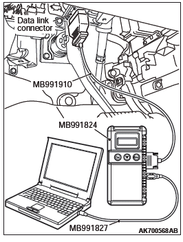
1. Ensure that the ignition switch is at the "LOCK" (OFF) position.
2. Start up the personal computer.
3. Connect special tool MB991827 to special tool MB991824 and the personal computer.
4. Connect special tool MB991910 to the special tool MB991824.
5. Connect special tool MB991910 to the data link connector of the vehicle.
6. Turn the special tool MB991824 power switch to the "ON" position.
NOTE: When the special tool MB991824 is energized, the special tool MB991824 indicator light will be illuminated in a green color.
7. Start the "M.U.T.-III system" on the personal computer and turn the ignition switch to the "ON" position.
8. Select "F.A.S.T./IMMO/Keyless/TPMS" button from the "System Select" screen. Then, select the applicable option code item and push the OK button.
9. Select "Coding" on the next screen.
10.Select "VIN Writing" on "Coding" screen.
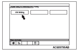
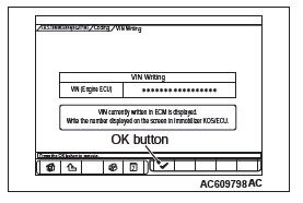
11.Push the OK button after the VIN written in the engine control module is displayed.
12.Push the OK button after "VIN Writing will start. Are you sure?" is displayed.
13.Push the OK button after "Completed" is displayed.
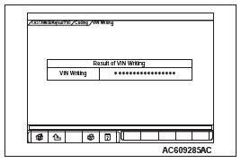
14.Result of VIN writing is displayed.
15.Resister the other ID code.
CODING LIST
CAUTION
With the ETACS functions being customized, if any of the ETACS-ECU variant coding and option coding items are changed, the customized contents are reset. In such case, the functions need to be recustomized.
Before troubleshooting, check that the coding data written into the engine control module and ETACS-ECU are normal. If they are not the same as the initial settings, various functions and systems will not work correctly.
VARIANT CODING
Required Special Tools:
- MB991958: Scan Tool (M.U.T.-III Sub Assembly)
- MB991824: Vehicle Communication Interface (V.C.I.)
- MB991827: M.U.T.-III USB Cable
- MB991910: M.U.T.-III Main Harness A (Vehicles with CAN communication system)
The coding data can be checked by operating scan tool MB991958.
NOTE: For details on how to use the scan tool MB991958, refer to the "M.U.T.-III Owner's manual".
CAUTION
To prevent damage to scan tool MB991958, always turn the ignition switch to the "LOCK" (OFF) position before connecting or disconnecting scan tool MB991958.
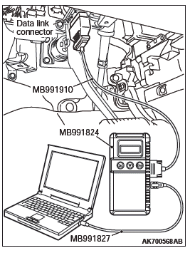
1. Ensure that the ignition switch is at the "LOCK" (OFF) position.
2. Start up the personal computer.
3. Connect special tool MB991827 to special tool MB991824 and the personal computer.
4. Connect special tool MB991910 to special tool MB991824.
5. Connect special tool MB991910 to the data link connector.
6. Turn the power switch of special tool MB991824 to the "ON" position.
NOTE: When special tool MB991824 is energized, special tool MB991824 indicator light will be illuminated in a green color.
7. Start the "M.U.T.-III system" on the personal computer.
8. Turn the ignition switch to the "ON" position.
9. Select "System select" from the start-up screen.
10.Select "From 2006 MY" under "Model Year". Check that "Vehicle Information" contents are correct.
11.On the system list screen, select "MPI/GDI/DIESEL" to check the engine control module data, and "ETACS" to check the ETACS-ECU data.
NOTE:
- If "Loading Option Setup" list is shown, click appropriate box.
- When you select "GasolineENG" system, a selection screen appears asking whether MITSUBISHI. Select a button that the engine belongs to.
12.Select "Coding".
13.Select "Coding Information & Copy".
14.If the displayed coding information is different from the corresponding initial setting in the list, replace the ECU with a correctly coded one. For replacement of the engine control module, refer to GROUP 13A, engine control module <2.4L Engine> or GROUP 13B, engine control module <3.0L Engine>. For replacement of the ETACS-ECU, refer to GROUP 54A, ETACS.
ENGINE CONTROL MODULE CODING DATA LIST
ETACS-ECU CODING DATA LIST
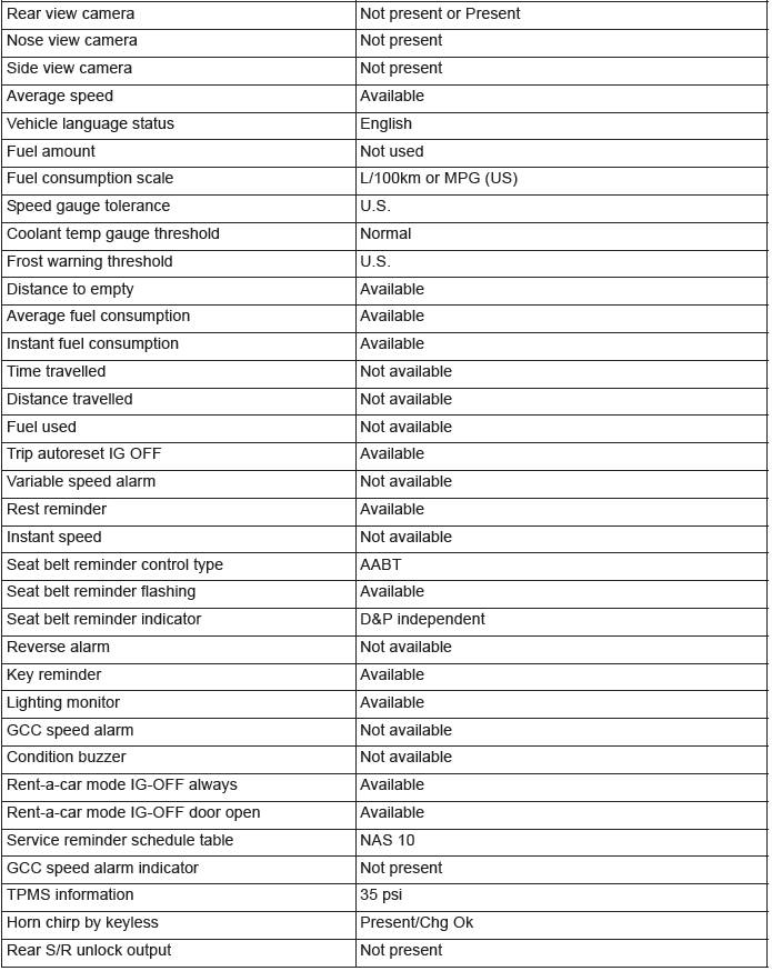
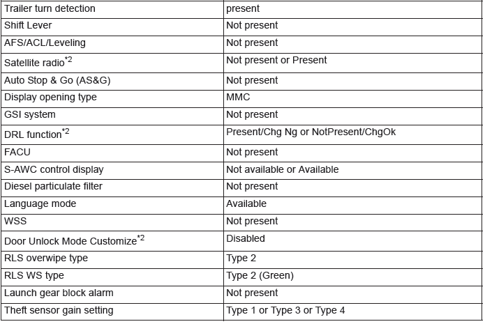
NOTE:
- *1: TPMS is an abbreviation of Tire Pressure Monitoring System, DRL of Daytime Running Light and AFS of Adaptive Front lighting System.
- *2: The setting can be changed by the option coding. Refer to.
OPTION CODING
Required Special Tools:
- MB991958: Scan Tool (M.U.T.-III Sub Assembly)
- MB991824: Vehicles Communication Interface (V.C.I.)
- MB991827: M.U.T.-III USB Cable
- MB991910: M.U.T.-III Main Harness A (Vehicles with CAN communication system)
CAUTION
If there is any item indicated by the option coding after equipment change, set ETACS-ECU so that the option coding data corresponds with the equipment content. Functions and systems do not work normally if the setting does not correspond with the equipment.
CAUTION
With the ETACS functions being customized, if any of the ETACS-ECU variant coding and option coding items are changed, the customized contents are reset. In such case, the functions need to be recustomized.
The ETACS-ECU option coding data can be checked or changed by operating scan tool MB991958.
- How to check option coding data
1. Connect the scan tool MB991958.
2. Turn the ignition switch to the "ON" position.
3. Select "System select" from the start-up screen.
4. Select "From 2006 MY" under "Model Year". Check that "Vehicle Information" contents are correct.
5. Select "MP/GDI/DIESEL" or "ETACS" from "System List", and then press "OK" button.
NOTE: If "Loading Option Setup" list is shown, click appropriate box.
6. Select "Coding".
7. Select "Option Coding Information".
8. Check the displayed option coding information.
- How to change option coding data
1. Connect the scan tool MB991958.
2. Turn the ignition switch to the "ON" position.
3. Select "System select" from the start-up screen.
4. Select "From 2006 MY" under "Model Year". Check that "Vehicle Information" contents are correct.
5. Select "MP/GDI/DIESEL" or "ETACS" from "System List", and then press "OK" button.
NOTE: If "Loading Option Setup" list is shown, click appropriate box.
6. Select "Coding".
7. Select "Option Coding".
8. Change to correct option coding data.
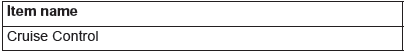
LIST <ENGINE CONTROL MODULE>
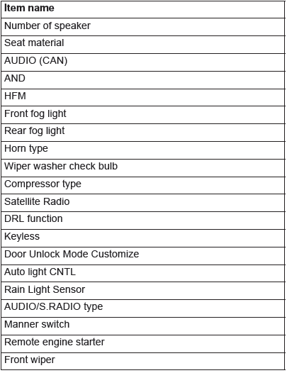
LIST <ETACS-ECU>
INITIALIZATION PROCEDURE FOR LEARNING VALUE IN MFI ENGINE
When the following service is performed, initialize the learning value.
- At replacing engine assembly*
- At replacing throttle body and at cleaning
- At replacing knock sensor
NOTE: *Initialize CVT-related learning value <2.4L> or A/T-related learning value <3.0L>.
INITIALIZATION PROCEDURE
Required Special Tools:
- MB991958: Scan Tool (M.U.T.-III Sub Assembly)
- MB991824: V.C.I.
- MB991827: M.U.T.-III USB Cable
- MB991910: M.U.T.-III Main Harness A
CAUTION
To prevent damage to scan tool MB991958, always turn the ignition switch to the "LOCK" (OFF) position before connecting or disconnecting scan tool MB991958.
1. After the ignition switch is in "LOCK" (OFF) position, connect scan tool MB991958 to the data link connector.
2. Turn the ignition switch to the "ON" position.
3. Select "MFI " from System select Screen of scan tool MB991958.
4. Select "Special Function" from MFI Screen.
5. Select "Learned value reset" from Special Function Screen.
6. Select "All learned value" from Learned value reset Screen.
7. Initialize the learning value by pressing the "OK" button.
8. After initializing the learning value, the learning value of MFI engine idling is necessary. (Refer to LEARNING PROCEDURE FOR IDLING IN MFI ENGINE).
ENGINE IDLING LEARNING PROCEDURE
PURPOSE
When the ECM is replaced, or when the learned value is initialized, the idle may not be stabilized. Carry out the learning method by following the procedures below.
LEARNING PROCEDURE
1. Start the engine and warm to reach 80ºC (176ºF) or more.
NOTE: When the engine coolant temperature is 80ºC (176ºF) or more, the warm-up is not needed if the ignition switch is in "ON" position once.
2. Turn the ignition switch to "LOCK" (OFF) position.
3. After 10 seconds or more, start the engine again.
4. For 10 minutes, carry out the idling under the condition shown below and then confirm the engine has the normal idling.
- Transaxle: P range
- Operation in ignition-related, fan and attachments: Not to be operated
- Engine coolant temperature: 80ºC (176ºF) or more
NOTE: If the engine stalls while idling, check for a dirty (on the throttle valve) of the throttle body and clean if needed.
Then perform the service from Procedure 1 again.
INITIALIZATION PROCEDURE FOR THROTTLE ACTUATOR CONTROL MOTOR
When the battery cable is disconnected and reconnected, throttle actuator control motor valve (Fully closed position) is eliminated, so that the throttle valve opening angle control would not be performed correctly. When the battery cable is disconnected and reconnected, initialize the throttle actuator control motor using the following procedure.
1. Turn the ignition switch to the "ON" position and then, place the ignition switch in "LOCK" (OFF) position.
2. For 10 seconds or more, keep the ignition switch in "LOCK" (OFF) position.
TIMING CHAIN LEARNED VALUE RESET <2.4L ENGINE>
Required Special Tools:
- MB991958: Scan Tool (M.U.T.-III Sub Assembly)
- MB991824: V.C.I.
- MB991827: M.U.T.-III USB Cable
- MB991910: M.U.T.-III Main Harness A
CAUTION
To prevent damage to scan tool MB991958, always turn the ignition switch to the "LOCK" (OFF) position before connecting or disconnecting scan tool MB991958.
1. After the ignition switch is in "LOCK" (OFF) position, connect scan tool MB991958 to the data link connector.
2. Turn the ignition switch to the "ON" position.
3. Select "MFI" form System select Screen of scan tool MB991958.
4. Select "Special Function" form MFI Screen.
5. Select "Timing chain maintenance" from Special Function Screen.
6. Select "Learned value reset" form Timing chain maintenance Screen.
7. Press "ON" to reset the learning value.
BATTERY CURRENT SENSOR CALIBRATION <2.4L ENGINE>
PURPOSE
The ECM carries out the electrical generation control according to the charge level of the battery, based on the battery current sensor signal. To improve the effect of reducing the fuel consumption by the electrical generation control, it is necessary to accurately detect the charge level of the battery. For this, if the following services are performed, carry out the battery current sensor calibration.
- Replacing the battery current sensor
- Replacing the ECM
LEARNING PROCEDURE
Required Special Tools:
- MB991958: Scan Tool (M.U.T.-III Sub Assembly)
- MB991824: V.C.I.
- MB991827: M.U.T.-III USB Cable
- MB991910: M.U.T.-III Main Harness A
CAUTION
To prevent damage to scan tool MB991958, always turn the ignition switch to the "LOCK" (OFF) position before connecting or disconnecting scan tool MB991958.
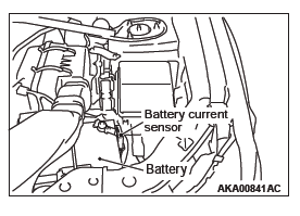
1. After the ignition switch is in "LOCK" (OFF) position, disconnect the battery cable from the negative battery terminal.
2. Remove the battery current sensor from the battery cable (Do not disconnect the battery current sensor connector).
3. Connect the battery cable without the battery current sensor to the negative battery terminal.
4. Connect scan tool MB991958 to the data link connector (But do not start the engine).
5. Turn the ignition switch to the ON position.
6. Select "MFI" from System select Screen of scan tool MB991958.
7. Select "Special Function" from MFI Screen.
8. Select "Learning" from Special Function Screen.
9. Select "Battery current SNSR.calibration" from Learning Screen.
10.Start the calibration by pressing the "OK" button.
11.Confirm that the scan tool MB991958 data list item No. 119 Battery current sensor calibration is "Completed".
12.After the ignition switch is in "LOCK" (OFF) position, disconnect scan tool MB991958.
13.Install the battery current sensor.
SERVICING ELECTRICAL SYSTEM
WARNING
Battery posts, terminals and related accessories contain lead and lead compounds. WASH HANDS AFTER HANDLING.
1. Note the following before proceeding with working on the electrical system.
Never perform unauthorized modifications to any electrical device or wiring. Such modifications might lead to a vehicle malfunction, over-capacity or short-circuit that could result in a fire in the vehicle.
CAUTION
- Before connecting or disconnecting the negative battery cable, be sure to turn the ignition switch to the "LOCK" (OFF) position and turn off the lights (If this is not done, there is the possibility of semiconductor parts being damaged).
- After completion of the work (and the negative battery
terminals is connected), warm up the engine and allow
it to idle for approximately 10 minutes under the conditions
described below in order to stabilize engine control
conditions, and then check to be sure that the idle
is satisfactory.
- Engine coolant temperature: 85 − 95ºC (185 − 203ºF)
- Lights and all accessories: OFF
- Transaxle: "P" position
- Steering wheel: straight-forward position
2. When servicing the electrical system, disconnect the negative cable terminal from the battery.
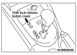
HOW TO SHIFT LOCK FORCED RELEASE
If the shift lever cannot be moved from the P position due to discharged battery or similar reasons, release the shift lock by observing the procedure below.
1. Turn the ignition switch to the position other than the LOCK (OFF) position.
2. Remove the shift lock forced release switch cover shown in the figure. While pressing the shift lock forced release switch with a screwdriver or a similar tool, move the selector lever.
VEHICLE WASHING

1. If high-pressure car-washing equipment or steam car-washing equipment is used to wash the vehicle, be sure to maintain the spray nozzle at a distance of at least approximately 40cm (16 in.) from any plastic parts and all opening parts (doors, luggage compartment, etc.).
2. If high-pressure car-washing equipment or steam car-washing equipment is used to wash the vehicle, be sure to observe the following instructions to prevent damages to the plastic parts.
- Spray nozzle distance: Approximately 40 cm (16 in.) or more
- Spray pressure: 3,900 kPa or less
- Spray temperature: 82 ºC (180ºF) or less
- Time of intensive spraying to one point: Within 30 seconds
APPLICATION OF ANTI-CORROSION AGENTS AND UNDERCOATS
Be careful not to apply oil or grease to the heated oxygen sensor.
If applied, the sensor may malfunction. Protect the heated oxygen sensor with a cover before applying anti-corrosion agent, etc.
FORM−IN−PLACE GASKET (FIPG)
The engine has several parts to which the form-in-place gasket (FIPG) is used. To sufficiently achieve the aims of this gasket, it is necessary to pay attention to the application amount, procedure, and surface status.
If the application amount is too small, a leakage will occur. If the application amount is excessive, the FIPG will overflow and cause a clogging or narrowing of water and oil paths. Therefore, to eliminate the leak from the joint, it is indispensable that the FIPG be applied with a correct amount and without any gap.
Because the FIPG used for the engine parts becomes hardened by the reaction with the atmospheric moisture, it is normally used for the metal flange section.
CAUTION
Reapply the FIPG with care to the followings.
1. Completely remove the old FIPG including the residue in gaps of parts.
2. Using Mitsubishi genuine parts cleaner (MZ100387) or equivalent, degrease the FIPG application surface carefully.
3. According to the FIPG application procedures, apply it accurately.
DISASSEMBLY
The parts installed with the FIPG can be disassembled easily without using any special method. However, in some cases, it is necessary to tear the sealant in between the mating surfaces by tapping the parts with a wooden hammer or similar tools. It is acceptable to lightly hit in a smooth, thin gasket scraper into the mating surface, but, in this case, a sufficient caution is required not to damage the mating surface. The oil pan FIPG cutter (Special tool: MD998727) is provided. Thus, use this special tool.
GASKET SURFACE CLEANING
Use a gasket scraper or wire brush to completely remove all the foreign materials adhering to the gasket surface. Check that the FIPG application surface is smooth. There must be no grease or foreign material adhesion to the gasket surface. Do not forget to remove the old FIPG remaining in the mounting hole and tapped hole.
APPLICATION PROCEDURE
Apply the FIPG with a specified diameter and without any gap.
Completely enclose around the mounting hole. When the FIPG is not hardened, it can be wiped off. Install the parts immediately after applying the FIPG. At the time of installation, prevent the FIPG from adhering to locations other than it is necessary.
After the installation, until a sufficient period of time (one hour or more) elapses, do not contact the oil or water to the application area. Also, do not start the engine. Because the FIPG application procedure may differ depending on the application area, apply the FIPG according to the procedure described in the text.
READ NEXT:
 Tightening Torque, Lubrication and Maintenance
Tightening Torque
Each torque value in the table is a standard value for
tightening under the following conditions.
1. Bolts, nuts and washers are all made of steel and
plated with zinc.
2. The threa
Maintenance Service
1. FUEL SYSTEM (TANK, PIPE LINE AND
CONNECTION, AND FUEL TANK FILLER TUBE
CAP) (CHECK FOR LEAKS)
Check for damage or leakage in the fuel lines and connections.
2. FUEL HOSES (CHECK CONDITION)
1. Inspe
Harness Connector Inspection (Electrical)
CONNECTOR CONTINUITY AND VOLTAGE TEST
Required Special Tools:
MB991219: Test Harness Set
MD998459: Test Harness
Follow the steps below to avoid causing poor connector contact
and/or reduced waterp
SEE MORE:
Inspection and maintenance followingrough road operation
After operating the vehicle in rough road conditions, be sure to perform the
following inspection and maintenance procedures:
● Check that the vehicle has not been damaged by rocks, gravel, etc.
● Carefully wash the vehicle with water.
Drive the vehicle slowly while lightly depressi
Balancer Shaft and Oil Pump Module
REMOVAL AND INSTALLATION
Pre-removal and Post-installation Operation
Engine Oil Pan Removal and Installation
Removal steps
Balancer shaft and oil pump
module
Required Special Tool:
MB991614: Angle Gauge
REMOVAL SERVICE POINT
BALANCER SHAFT AND OIL PUMP MODULE
REMOVAL
CAUTION
Never turn
