Mitsubishi Outlander: Specification(s), Front/Rear Bumper Assembly
Specification(s)
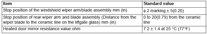
SERVICE SPECIVFICATIONS
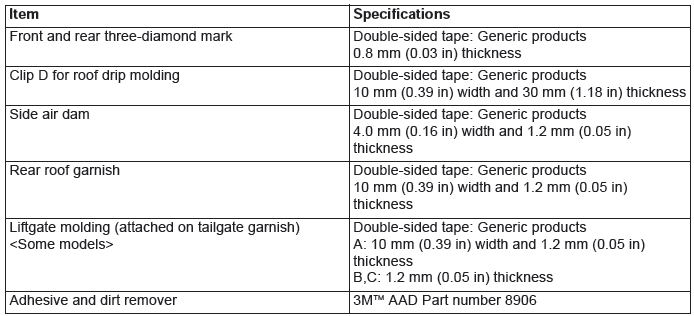
ADHESIVES
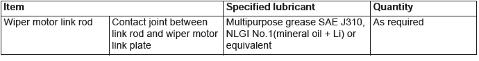
LUBRICANT
Front Bumper Assembly
REMOVAL AND INSTALLATION
Pre-removal and post-installation operation
- Headlight support panel cover removal and installation
- Engine room under cover front removal and installation
- Splash shield removal and installation
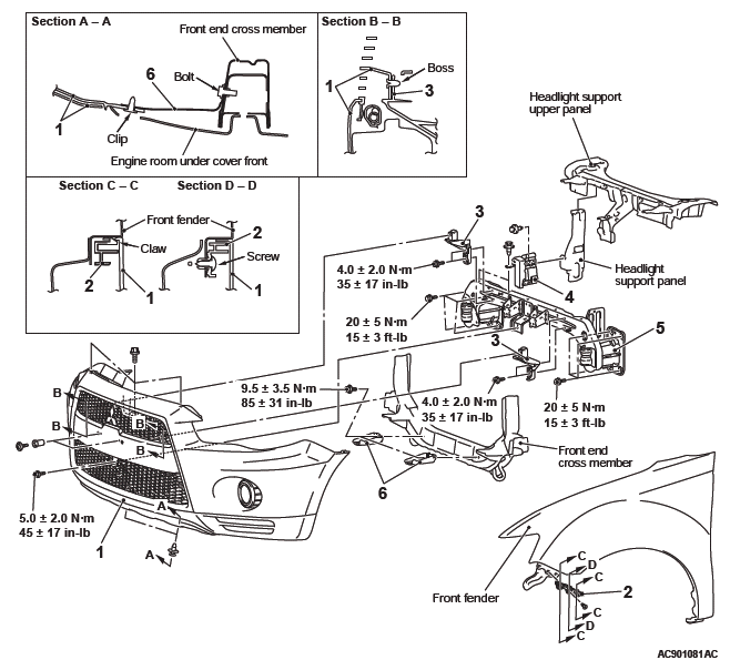
Removal steps
- Fog light connector connection <Vehicles with fog light>
- Front bumper assembly
- Front bumper side bracket
- Ambient temperature sensor
- Headlight bracket
- Front end panel guide
- Horn
- Front harness
- Front bumper reinforcement
- Bumper lower bracket
DISASSEMBLY AND REASSEMBLY
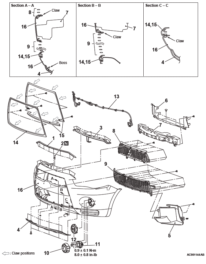
Disassembly steps
- Hood weatherstrip front
- Rivet
- Front bumper reinforcement
- Front bumper extension A <Some models>
- Oil cooler duct <Vehicles with oil cooler>
- Front bumper air guide duct
- Front bumper core
- Radiator grille
- Front bumper grille
- Front fog light bezel <Vehicles with front fog lights>
- Front fog light <Vehicles with front fog light>
- Front bumper light hole cover <Vehicles without front fog light>
- Front bumper harness
- Front bumper center garnish <Type 1: Material color>
- Front bumper center garnish <Type 2: Chromium plating>
- Front bumper face
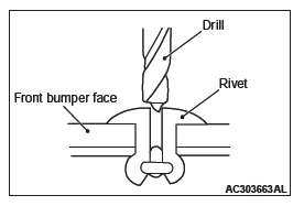
DISASSEMBLY SERVICE POINT
RIVETS REMOVAL
Use a drill [(φ 4.0 mm(0.16 in) ] to make a hole in the rivet to break it, and remove the rivet.
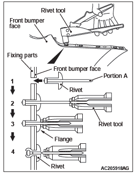
REASSEMBLY SERVICE POINT
RIVETS INSTALLATION
Use a rivet tool shown as in the illustration to connect the parts with rivets by the following procedures:
1. Insert the rivet into a corresponding location.
2. Set the rivet tool at a portion A of rivet.
3. While pushing the flange surface of the rivet onto parts to be fixed with the rivet tool, press the handle of the tool.
4. Thin part of portion A of the rivet will be cut off and the parts is fixed in position.
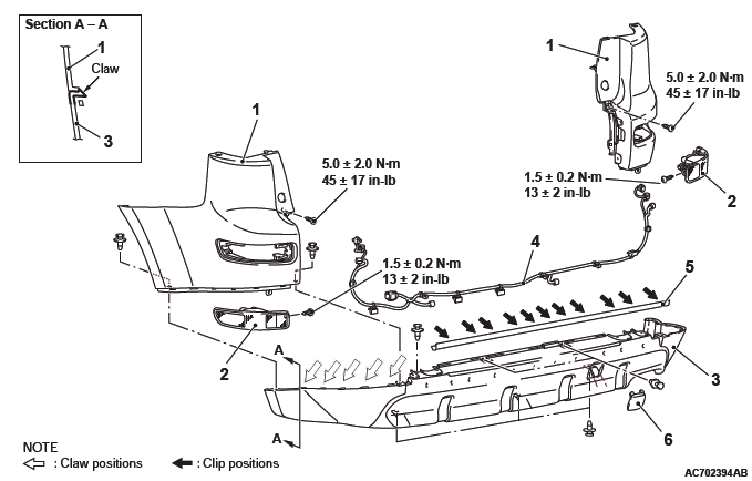
Rear Bumper Assembly
REMOVAL AND INSTALLATION
Removal steps
- Rear combination light
- Rear bumper harness connector connection
- Splash shield mounting clips
- Rear bumper cover
- Rear bumper assembly
- Rear bumper beam assembly
- Rear bumper side bracket
- Rear bumper face side bracket
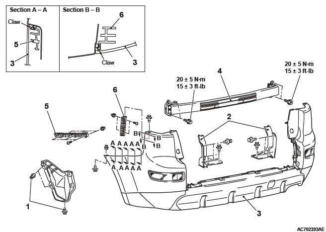
DISASSEMBLY AND ASSEMBLY
Disassembly steps
- Rear side marker light connector connection
- Rear corner bumper
- Rear side marker light
- Rear bumper face
- Rear bumper harness
- Rear bumper weatherstrip
- Towing cover
READ NEXT:
 Radiator Grille, Moldings, Garnishes
Radiator Grille
REMOVAL AND INSTALLATION
Removal steps
Headlight support panel cover
Front bumper assembly
Radiator grille
Front-three diamond mark
Headlight support upper panel
cover
Mol
Door Sash Tape
SPECIAL TOOL
REMOVAL AND INSTALLATION
Pre-removal and post-installation operation
Door Trim Assembly Removal and Installation
Door Beltline Weatherstrip Inner Removal and Installation
Door Openin
Side Air Dam, Under Cover, Roof Rail, Liftgate Spoiler
Side Air Dam
REMOVAL AND INSTALLATION
Removal
Side air dam
REMOVAL SERVICE POINT
SIDE AIR DAM REMOVAL
Gently lift and remove the side air dam. If there is any double-
sided tape remaining on the s
SEE MORE:
How To Use Troubleshooting, Inspection Service Points
TROUBLESHOOTING CONTENTS
DANGER
The SRS-ECU adopts the rollover specification
that the curtain airbag and seat belt
pre-tensioner operate at the occurrence of
rollover. Therefore, do not tilt the vehicle to
the right and left with the IG ON or tilt the
SRS-ECU to the right and left with the IG ON
an
Diagnosis S-AWC (Super All Wheel Control)
TROUBLESHOOTING STRATEGY
Refer to GROUP 00 − How to Use Troubleshooting/
Inspection Service Points.
PRECAUTIONS FOR DIAGNOSIS
Before diagnosis, check that all the following items
are normal.
A normal steering wheel is installed correctly to
the neutral position of steering column shaft
as
