Mitsubishi Outlander: Symptom Procedures (Power Window)
INSPECTION PROCEDURE C-1: Power Windows do not Work at All.
CAUTION Before replacing the ECU, ensure that the power supply circuit, the ground circuit and the communication circuit are normal.
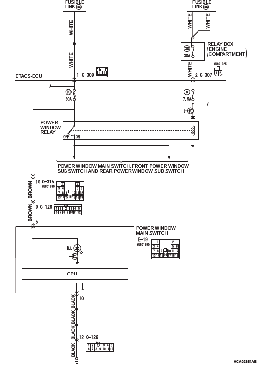
Power Window Power Supply Circuit
CIRCUIT OPERATION
The ETACS-ECU turns on the power window relay to activate the power windows when the ignition switch (IG1) is turned to the "ON" position.
TROUBLESHOOTING HINTS
- The wiring harness or connectors may have loose, corroded, or damaged terminals, or terminals pushed back in the connector
- The power main switch may be defective
- The ETACS-ECU may be defective
DIAGNOSTIC PROCEDURE
Required Special Tools:
- MB992006: Extra fine probe
- MB991223: Harness set
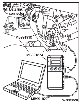
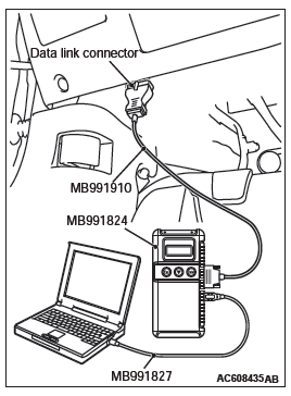
- MB991958: Scan Tool (M.U.T.-III Sub Assembly)
- MB991824: Vehicles Communication Interface (V.C.I.)
- MB991827: M.U.T.-III USB Cable
- MB991910: M.U.T.-III Main Harness A (Vehicles with CAN communication system)
STEP 1. Check the power supply system.
With the ignition switch in the LOCK (OFF) position, check if the following function operates normally:
- Hazard warning light
- Central door locking system
Q: Is the check result normal?
YES : Go to Step 2.
NO : Refer to GROUP 54A, Malfunction of ETACS-ECU power supply circuit.
STEP 2. Using scan tool MB991958, read the diagnostic trouble code.
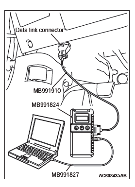
CAUTION To prevent damage to scan tool MB991958, always turn the ignition switch to the "LOCK" (OFF) position before connecting or disconnecting scan tool MB991958.
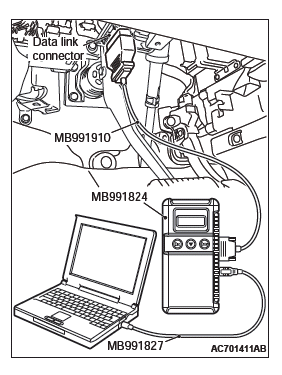
- Connect scan tool MB991958. Refer to GROUP 42B, "How to connect scan tool (M.U.T.-III)".
- Turn the ignition switch to the "ON" position.
- Check whether the ETACS-ECU related DTC is set.
- Turn the ignition switch to the "LOCK" (OFF) position.
Q: Is the DTC set?
YES : Diagnose the ETACS-ECU. Refer to GROUP 54A, Diagnosis.
NO : Go to Step 3.
STEP 3. Using scan tool MB991958, check data list.
Check the signals related to the power window operation.
CAUTION To prevent damage to scan tool MB991958, always turn the ignition switch to the "LOCK" (OFF) position before connecting or disconnecting scan tool MB991958.
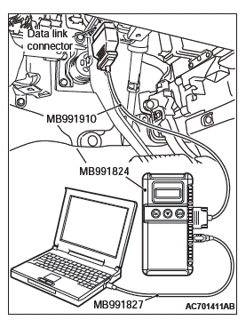
- Connect scan tool MB991958. Refer to GROUP 42B, "How to connect scan tool (M.U.T.-III)".
- Turn the ignition switch to the "ON" position.
- Check the data list of the ETACS.
- Turn the ignition switch to the LOCK (OFF) position.
- Turn the ignition switch to the "LOCK" (OFF) position.
OK: Normal condition is displayed.
Q: Is the check result normal?
YES : Go to Step 4.
NO : Refer to GROUP 54A, Inspection Procedure 2: ETACS-ECU does not receive any signal from the ignition switch (IG1).
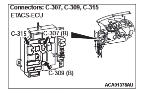
STEP 4. Check ETACS-ECU connector C-309 for loose, corroded or damaged terminals, or terminals pushed back in the connector.
Q: Is ETACS-ECU connector C-309 in good condition?
YES : Go to Step 5.
NO : Repair or replace the damaged component(s). Refer to GROUP 00E, Harness Connector Inspection. Verify that the power window works normally.
STEP 5. Check the fusible link (34) line of power supply circuit to the ETACS-ECU. Measure the voltage at ETACS-ECU connector C-309.
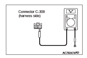
- Disconnect ETACS-ECU connector C-309 and measure the voltage available at the wiring harness side of the connector.
- Measure the voltage between terminal 1 and ground.
- The voltage should measure approximately 12 volts (battery positive voltage).
Q: Is the measured voltage approximately 12 volts (battery positive voltage)?
YES : Go to Step 7.
NO : Go to Step 6.
STEP 6. Check the wiring harness between ETACS-ECU connector C-309 (terminal 1) and fusible link (34).
- Check the power supply line for open circuit and short circuit.
Q: Is the wiring harness between ETACS-ECU connector C-309 (terminal 1) and fusible link (34) in good condition?
YES : No action is necessary and testing is complete.
NO : The wiring harness may be damaged or the connector(s) may have loose, corroded or damaged terminals, or terminals pushed back in the connector.
Repair the wiring harness as necessary. Check that the power window works normally.
STEP 7. Check ETACS-ECU connector C-307 for loose, corroded or damaged terminals, or terminals pushed back in the connector.
Q: Is ETACS-ECU connector C-307 in good condition?
YES : Go to Step 8.
NO : Repair or replace the damaged component(s). Refer to GROUP 00E, Harness Connector Inspection. Verify that the power window works normally.
STEP 8. Check the fusible link (36) line of power supply circuit to the ETACS-ECU. Measure the voltage at ETACS-ECU connector C-307.
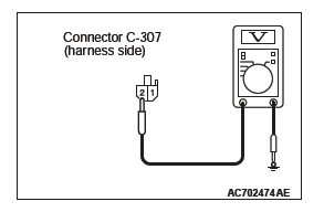
- Disconnect ETACS-ECU connector C-307 and measure the voltage available at the wiring harness side of the connector.
- Measure the voltage between terminal 2 and ground.
- The voltage should measure approximately 12 volts (battery positive voltage).
Q: Is the measured voltage approximately 12 volts (battery positive voltage)?
YES : Go to Step 10.
NO : Go to Step 9.
STEP 9. Check the wiring harness between ETACS-ECU connector C-307 (terminal 2) and fusible link (36).
- Check the power supply line for open circuit and short circuit.
Q: Is the wiring harness between ETACS-ECU connector C-307 (terminal 2) and fusible link (36) in good condition?
YES : No action is necessary and testing is complete.
NO : The wiring harness may be damaged or the connector(s) may have loose, corroded or damaged terminals, or terminals pushed back in the connector.
Repair the wiring harness as necessary. Check that the power window works normally.
STEP 10. Check power window main switch connector E-19 for loose, corroded or damaged terminals, or terminals pushed back in the connector.
Q: Is power window main switch connector E-19 in good condition?
YES : Go to Step 11.
NO : Repair or replace the damaged component(s). Refer to GROUP 00E, Harness Connector Inspection. Verify that the power window works normally.
STEP 11. Check the ETACS-ECU connector C-315 line circuit to the power window main switch. Measure the voltage at power window main switch connector E-19.
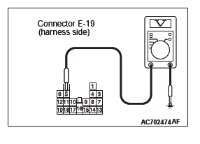
- Disconnect power window main switch connector E-19 and measure the voltage available at the wiring harness side of the connector.
- Measure the voltage between terminal 5 and ground.
- The voltage should measure approximately 12 volts (battery positive voltage).
Q: Is the measured voltage approximately 12 volts (battery positive voltage)?
YES : Go to Step 14.
NO : Go to Step 12.
STEP 12. Check ETACS-ECU connector C-315 for loose, corroded or damaged terminals, or terminals pushed back in the connector.
Q: Is ETACS-ECU connector C-315 in good condition?
YES : Go to Step 13.
NO : Repair or replace the damaged component(s). Refer to GROUP 00E, Harness Connector Inspection. Verify that the power window works normally.
STEP 13. Check the wiring harness between ETACS-ECU connector C-315 (terminal 10) and power window main switch connector E-19 (terminal 5).
- Check the power supply line for open circuit and short circuit.
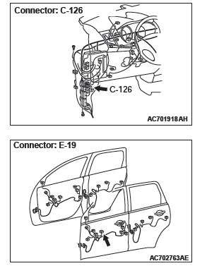
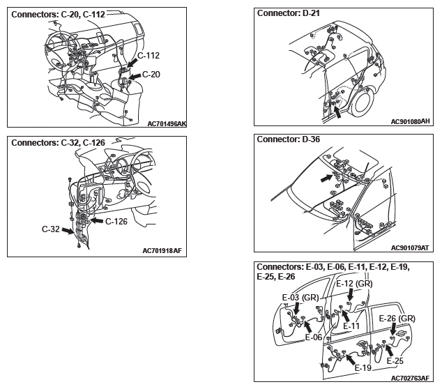
NOTE: Also check intermediate connector C-126 for loose, corroded, or damaged terminals, or terminals pushed back in the connector. If intermediate connector C-126 is damaged, repair or replace the damaged component(s) as described in GROUP 00E, Harness Connector Inspection.
Q: Is the wiring harness between ETACS-ECU connector C-315 (terminal 10) and power window main switch connector E-19 (terminal 5) in good condition?
YES : No action is necessary and testing is complete.
NO : The wiring harness may be damaged or the connector(s) may have loose, corroded or damaged terminals, or terminals pushed back in the connector.
Repair the wiring harness as necessary. Check that the power window works normally.
STEP 14. Check the ground circuit to the power window main switch. Measure the resistance at power window main switch connector E-19.
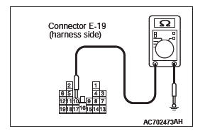
- Disconnect power window main switch connector E-19 and measure the resistance available at the wiring harness side of the connector.
- Measure the resistance value between terminal 10 and ground.
- The resistance should be 2 ohms or less.
Q: Is the measured resistance 2 ohms or less?
YES : Go to Step 16.
NO : Go to Step 15.
STEP 15. Check the wiring harness between power window main switch connector E-19 (terminal 10) and ground.
- Check the ground line for open circuit and short circuit.
NOTE: Also check intermediate connector C-126 for loose, corroded, or damaged terminals, or terminals pushed back in the connector. If intermediate connector C-126 is damaged, repair or replace the damaged component(s) as described in GROUP 00E, Harness Connector Inspection.
Q: Is the wiring harness between power window main switch connector E-19 (terminal 10) and ground in good condition?
YES : No action is necessary and testing is complete.
NO : The wiring harness may be damaged or the connector(s) may have loose, corroded or damaged terminals, or terminals pushed back in the connector.
Repair the wiring harness as necessary. Check that the sunroof works normally.
STEP 16. Retest the system.
Check that the all the power windows work normally.
Q: Is the check result normal?
YES : No action is necessary and testing is complete.
NO : Replace ETACS-ECU. Check that the power window works normally.
INSPECTION PROCEDURE C-2: Driver's Power Window does not Work by means of The Power Window Main Switch.
CAUTION Before replacing the ECU, ensure that the input and output signal circuits are normal.
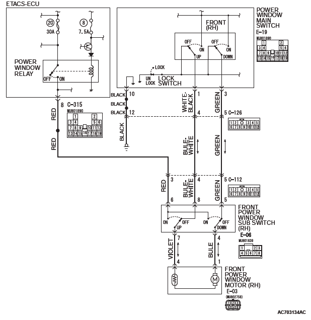
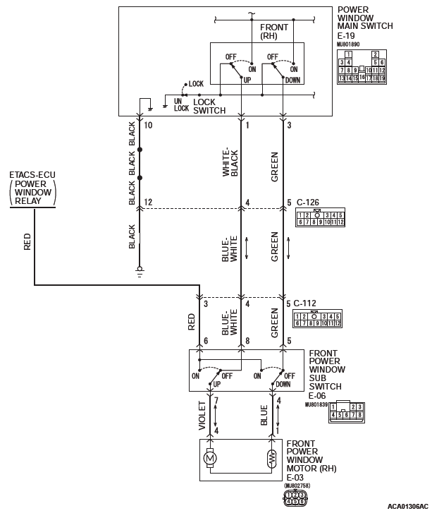
Driver's Power Window Circuit
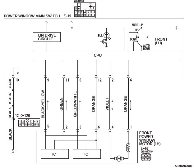
CIRCUIT OPERATION
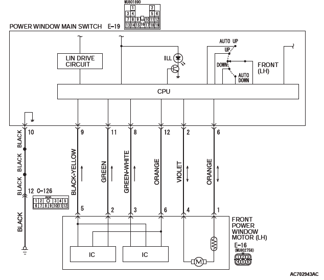
The front power window motor (LH) receives a signal ("UP", "DOWN", "AUTO UP" or "AUTO DOWN") from the front power window main switch and controls the driver's power window.
TECHNICAL DESCRIPTION (COMMENT)
The power window main switch or the front power window motor (LH) may be defective.
TROUBLESHOOTING HINTS
- The power window main switch may be defective
- The front power window motor (LH) may be defective
- The wiring harness or connectors may have loose, corroded, or damaged terminals, or terminals pushed back in the connector
DIAGNOSTIC PROCEDURE
Required Special Tools:
- MB992006: Extra fine probe
- MB991223: Harness set
- MB991958: Scan Tool (M.U.T.-III Sub Assembly)
- MB991824: Vehicles Communication Interface (V.C.I.)
- MB991827: M.U.T.-III USB Cable
- MB991910: M.U.T.-III Main Harness A (Vehicles with CAN communication system)
STEP 1. Using scan tool MB991958, read the diagnostic trouble code.
CAUTION To prevent damage to scan tool MB991958, always turn the ignition switch to the "LOCK" (OFF) position before connecting or disconnecting scan tool MB991958.
- Connect scan tool MB991958. Refer to GROUP 42B, "How to connect scan tool (M.U.T.-III)".
- Turn the ignition switch to the "ON" position.
- Check whether the ETACS-ECU related DTC is set.
- Turn the ignition switch to the "LOCK" (OFF) position.
Q: Is the DTC set?
YES : Diagnose the ETACS-ECU. NO : Go to Step 2.
STEP 2. Check the power window main switch.
Check that the passenger's or rear power window works by means of the power window main switch.
Q: Is the check result normal?
YES : Go to Step 3.
NO : Refer to P.42A.
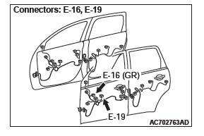
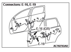
STEP 3. Check power window main switch connector E-19, front power window motor (LH) connector E-16 for loose, corroded or damaged terminals, or terminals pushed back in the connector.
Q: Are power window main switch connector E-19, front power window motor (LH) connector E-16 in good condition?
YES : Go to Step 4.
NO : Repair or replace the damaged component(s). Refer to GROUP 00E, Harness Connector Inspection. Verify that the power window works normally.
STEP 4. Check the wiring harness between power window main switch connector E-19 (terminals 2, 6) and front power window motor (LH) connector E-16 (terminals 4, 1).
- Check the power supply lines for open circuit and short circuit.
Q: Is the wiring harness between power window main switch connector E-19 (terminals 2, 6) and front power window motor (LH) connector E-16 (terminals 4, 1) in good condition?
YES : Go to Step 5.
NO : The wiring harness may be damaged or the connector(s) may have loose, corroded or damaged terminals, or terminals pushed back in the connector.
Repair the wiring harness as necessary. Check that the power works normally.
STEP 5. Retest the system.
Check that the driver's power window works by means of the power window main switch.
Q: Is the check result normal?
YES : No action is necessary and testing is complete.
NO : Replace the front power window motor (LH). Check that the power window works normally.
INSPECTION PROCEDURE C-3: Relevant Power Window(s) does not Work by means of The Front and Rear Passenger's Power Window Sub Switches.
CAUTION Before replacing the ECU, ensure that the power supply circuit, the ground circuit and the communication circuit are normal.
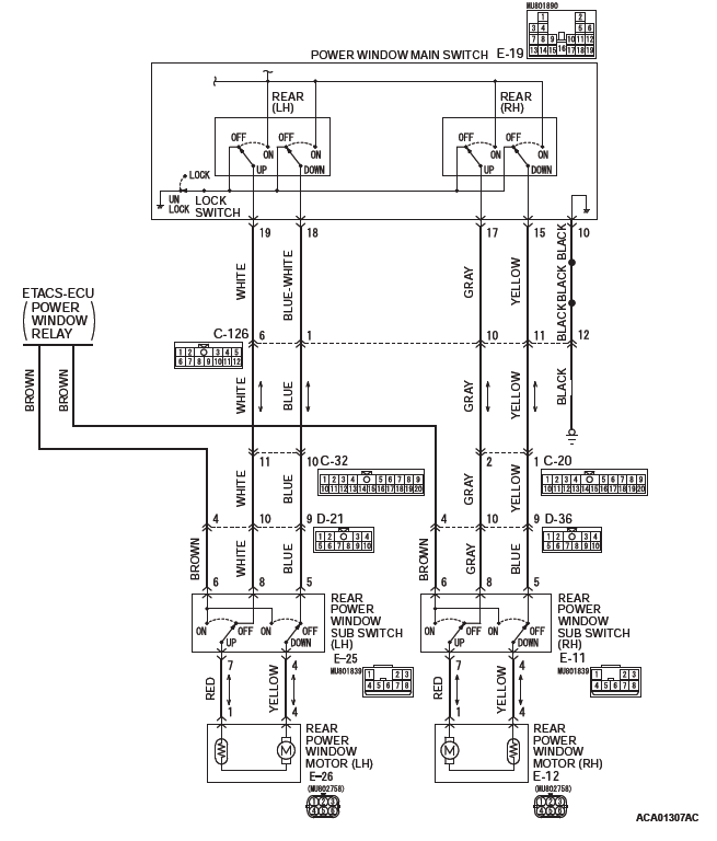
Power Window (Passenger) Circuit
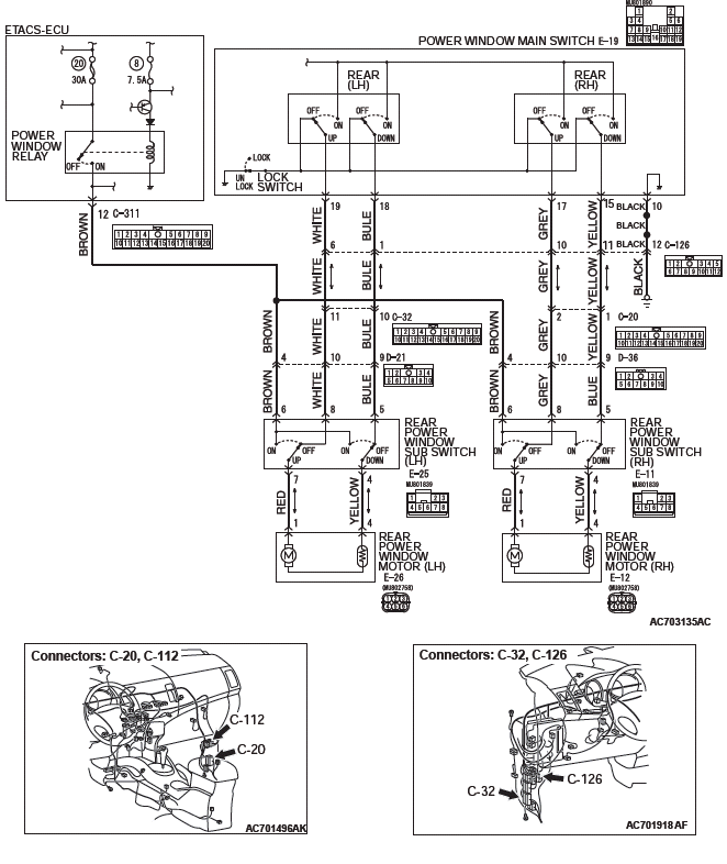
Power Window (Rear) Circuit
CIRCUIT OPERATION
Power window motors raise or lower the door windows when the front passenger's or rear passenger's sub switch is moved to "UP" or "DOWN" position.
TECHNICAL DESCRIPTION (COMMENT)
A power window sub switch or power window motor may be defective. Or, the power window lock switch (incorporated in the power window main switch in the driver's door) may remain pressed to the "LOCK" position.
TROUBLESHOOTING HINTS
- The power window main switch may be defective
- The front power window sub switch may be defective
- The rear power window sub switches may be defective
- The front power window motor (RH) may be defective
- The rear power window motors may be defective
- The wiring harness or connectors may have loose, corroded, or damaged terminals, or terminals pushed back in the connector
DIAGNOSTIC PROCEDURE
STEP 1. Check the power window lock switch.
Q: Is the power window lock switch in the "UNLOCK" position?
YES : Go to Step 2.
NO : Operate the power window lock switch to the "UNLOCK" position. When the power window sub switch is operated, the power windows should raise and lower normally.
STEP 2. Check power window main switch connector E-19 for loose, corroded or damaged terminals, or terminals pushed back in the connector.
Q: Is power window main switch connector E-19 in good condition?
YES : Go to Step 3.
NO : Repair or replace the damaged component(s). Refer to GROUP 00E, Harness Connector Inspection. When the front power window sub switch (RH) is operated, the front power window (RH) should raise and lower normally.
STEP 3. Check which door window does not move.
Q: Which door window does not move?
Front passenger's door : Go to Step 4.
Rear left door : Go to Step 13.
Rear right door : Go to Step 22.
STEP 4. Check front power window sub switch connector E-06 and front power window motor (RH) connector E-03 for loose, corroded or damaged terminals, or terminals pushed back in the connector.
Q: Are front power window sub switch connector E-06 and front power window motor (RH) connector E-03 in good condition?
YES : Go to Step 5.
NO : Repair or replace the damaged component(s). Refer to GROUP 00E, Harness Connector Inspection. When the front power window sub switch (RH) is operated, the front power window (RH) should raise and lower normally.
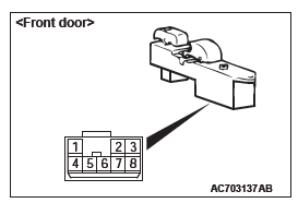
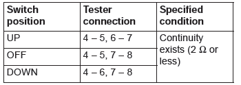
STEP 5. Check the front power window sub switch for continuity.
- Remove the front power window sub switch. Refer to GROUP 42A, Door, Door Glass and Regulator.
- Check continuity when the front power window sub switch is operated to "UP" or "DOWN" position.
Q: Is the front power window sub switch normal?
YES : Go to Step 6.
NO : Replace the front power window sub switch. When the front power window sub switch is operated, the front power window should raise and lower normally.
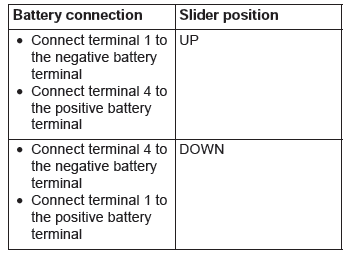
STEP 6. Check the front power window motor (RH).
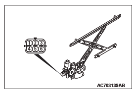
- Remove the front power regulator assembly (RH). Refer to GROUP 42A, Door, Door Glass and Regulator.
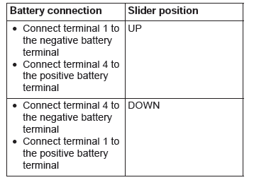
- Connect a battery to the motor terminal, and check that the motor runs freely.
Q: Is the front power window motor (RH) normal?
YES : Go to Step 7.
NO : Replace the front power assembly (RH). When the front power window sub switch (RH) is operated, the front power window (RH) should raise and lower normally.
STEP 7. Check the battery power supply circuit to the front power window sub switch. Measure the voltage at front power window sub switch connector E-06.
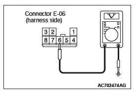
- Disconnect front power window sub switch connector E-06 and measure the voltage available at the wiring harness side of the connector.
- Measure the voltage between terminal 6 and ground.
- The voltage should measure approximately 12 volts (battery positive voltage).
Q: Is the measured voltage approximately 12 volts (battery positive voltage)?
YES : Go to Step 10.
NO : Go to Step 8.
STEP 8. Check ETACS-ECU connector C-315 for loose, corroded or damaged terminals, or terminals pushed back in the connector.
Q: Is ETACS-ECU connector C-315 in good condition?
YES : Go to Step 9.
NO : Repair or replace the damaged component(s). Refer to GROUP 00E, Harness Connector Inspection. When the front power window sub switch (RH) is operated, the front power window (RH) should raise and lower normally.
STEP 9. Check the wiring harness between ETACS-ECU connector C-315 (terminal 8) and front power window sub switch connector E-06 (terminal 6).
- Check the power supply line for open circuit and short circuit.
NOTE: Also check intermediate connector C-112. If intermediate connectors C-112 is damaged, repair or replace the damaged component(s) as described in GROUP 00E, Harness Connector Inspection.
Q: Is the wiring harness between ETACS-ECU connector C-315 (terminal 8) and front power window sub switch connector E-06 (terminal 6 in good condition?
YES : No action is necessary and testing is complete.
NO : The wiring harness may be damaged or the connector(s) may have loose, corroded or damaged terminals, or terminals pushed back in the connector.
Repair the wiring harness as necessary. When the front power window sub switch is operated, the front power window (RH) should raise and lower normally.
STEP 10. Check the ground circuit to the front power window sub switch. Measure the resistance at front power window sub switch connector E-06.
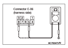
- Disconnect front power window sub switch connector E-06 and measure the resistance available at the wiring harness side of the connector.
- Measure the resistance value between terminal 5 and ground, and also between terminal 8 and ground.
- The resistance should be 2 ohms or less.
Q: Is the measured resistance 2 ohms or less?
YES : Go to Step 12.
NO : Go to Step 11.
STEP 11. Check the wiring harness between power window main switch connector E-19 (terminals 1, 3) and front power window sub switch connector E-06 (terminals 8, 5).
- Check the power supply lines for open circuit and short circuit.
NOTE: Also check intermediate connectors C-112 and C-126.
If intermediate connector C-112 or C-126 is damaged, repair or replace the damaged component(s) as described in GROUP 00E, Harness Connector Inspection.
Q: Is the wiring harness between power window main switch connector E-19 (terminals 1, 3) and front power window sub switch connector E-06 (terminals 8, 5) in good condition?
YES : Replace the power window main switch. When the front power window sub switch (RH) is operated, the front power window (RH) should raise and lower normally.
NO : The wiring harness may be damaged or the connector(s) may have loose, corroded or damaged terminals, or terminals pushed back in the connector.
Repair the wiring harness as necessary. When the front power window sub switch (RH) is operated, the front power window (RH) should raise and lower normally.
STEP 12. Check the wiring harness between front power window sub switch connector E-06 (terminals 4, 7) and front power window motor (RH) connector E-03 (terminals 1, 4).
- Check the power supply lines for open circuit and short circuit.
Q: Is the wiring harness between front power window sub switch connector E-06 (terminals 4, 7) and front power window motor (RH) connector E-03 (terminals 1, 4) in good condition?
YES : No action is necessary and testing is complete.
NO : The wiring harness may be damaged or the connector(s) may have loose, corroded or damaged terminals, or terminals pushed back in the connector.
Repair the wiring harness as necessary. When the front power window sub switch (RH) is operated, the front power window (RH) should raise and lower normally.
STEP 13. Check rear power window sub switch (LH) connector E-25 and rear power window motor (LH) connector E-26 for loose, corroded or damaged terminals, or terminals pushed back in the connector.
Q: Are rear power window sub switch (LH) connector E-25 and rear power window motor (LH) connector E-26 in good condition?
YES : Go to Step 14.
NO : Repair or replace the damaged component(s). Refer to GROUP 00E, Harness Connector Inspection. When the rear power window sub switch (LH) is operated, the rear power window (LH) should raise and lower normally.
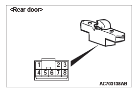
STEP 14. Check the rear power window sub switch (LH) for continuity.
-
Remove the rear power window sub switch (LH). Refer to GROUP 42A, Door, Door Glass and Regulator.
-
Check continuity when the rear power window sub switch (LH) is operated to "UP" or "DOWN" position.
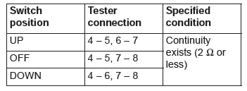
Q: Is the rear power window sub switch (LH) normal?
YES : Go to Step 15.
NO : Replace the rear power window sub switch (LH).
When the rear power window sub switch (LH) is operated, the rear power window (LH) should raise and lower normally.
STEP 15. Check the rear power window motor (LH).
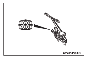
- Remove the rear power window regulator assembly (LH).
- Connect a battery to the motor terminal, and check that the motor runs freely.
Q: Is the rear power window motor (LH) normal?
YES : Go to Step 16.
NO : Replace the rear power window motor (LH). When the rear power window sub switch (LH) is operated, the rear power window (LH) should raise and lower normally.
STEP 16. Check the battery power supply circuit to the rear power window sub switch (LH). Measure the voltage at rear power window sub switch (LH) connector E-25.
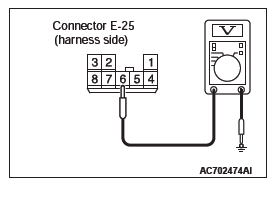
- Disconnect rear power window sub switch (LH) connector E-25 and measure the voltage available at the wiring harness side of the connector.
- Measure the voltage between terminal 6 and ground.
- The voltage should measure approximately 12 volts (battery positive voltage).
Q: Is the measured voltage approximately 12 volts (battery positive voltage)?
YES : Go to Step 19.
NO : Go to Step 17.
STEP 17. Check ETACS-ECU connector C-311 for loose, corroded or damaged terminals, or terminals pushed back in the connector.
Q: Is ETACS-ECU connector C-311 in good condition?
YES : Go to Step 18.
NO : Repair or replace the damaged component(s). Refer to GROUP 00E, Harness Connector Inspection. When the rear power window sub switch (LH) is operated, the rear power window (LH) should raise and lower normally.
STEP 18. Check the wiring harness between ETACS-ECU connector C-311 (terminal 12) and rear power window sub switch (LH) connector E-25 (terminal 6).
- Check the power supply line for open circuit and short circuit.
NOTE: Also check intermediate connectors D-21. If intermediate connector D-21 is damaged, repair or replace the connector as described in GROUP 00E, Harness Connector Inspection.
Q: Is the wiring harness between ETACS-ECU connector C-311 (terminal 12) and rear power window sub switch (LH) connector E-25 (terminal 6) in good condition?
YES : No action is necessary and testing is complete.
NO : The wiring harness may be damaged or the connector(s) may have loose, corroded or damaged terminals, or terminals pushed back in the connector.
Repair the wiring harness as necessary. When the rear power window sub switch (LH) is operated, the rear power window (LH) should raise and lower normally.
STEP 19. Check the ground circuit to the rear power window sub switch (LH). Measure the resistance at rear power window sub switch (LH) connector E-25.
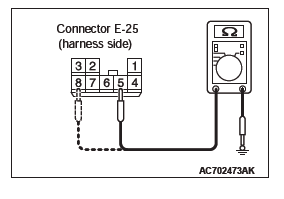
- Disconnect rear power window sub switch (LH) connector E-25 and measure the resistance available at the wiring harness side of the connector.
- Measure the resistance value between terminal 5 and ground, and also between terminal 8 and ground.
- The resistance should be 2 ohms or less.
Q: Is the measured resistance 2 ohms or less?
YES : Go to Step 21.
NO : Go to Step 20.
STEP 20. Check the wiring harness between power window main switch connector E-19 (terminals 18, 19) and rear power window sub switch (LH) connector E-25 (terminals 5, 8).
- Check the power supply lines for open circuit and short circuit.
NOTE: Also check intermediate connectors C-32, C-126 and D-21. If intermediate connector C-32, C-126 or D-21 is damaged, repair or replace the damaged component(s) as described in GROUP 00E, Harness Connector Inspection.
Q: Is the wiring harness between power window main switch connector E-19 (terminals 18, 19) and rear power window sub switch (LH) connector E-25 (terminals 5, 8) in good condition?
YES : Replace the power window main switch. When the rear power window sub switch (LH) is operated, the rear power window (LH) should raise and lower normally.
NO : The wiring harness may be damaged or the connector(s) may have loose, corroded or damaged terminals, or terminals pushed back in the connector.
Repair the wiring harness as necessary. When the rear power window sub switch (LH) is operated, the rear power window (LH) should raise and lower normally.
STEP 21. Check the wiring harness between rear power window sub switch (LH) connector E-25 (terminals 4, 7) and rear power window motor (LH) connector E-26 (terminals 4, 1).
- Check the power supply line for open circuit and short circuit.
Q: Is the wiring harness between rear power window sub switch (LH) connector E-25 (terminals 4, 7) and rear power window motor (LH) connector E-26 (terminals 4, 1) in good condition?
YES : Replace the power window main switch. When the rear power window sub switch (LH) is operated, the rear power window (LH) should raise and lower normally.
NO : The wiring harness may be damaged or the connector(s) may have loose, corroded or damaged terminals, or terminals pushed back in the connector.
Repair the wiring harness as necessary. When the rear power window sub switch (LH) is operated, the rear power window (LH) should raise and lower normally.
STEP 22. Check rear power window sub switch (RH) connector E-11 and rear power window motor (RH) connector E-12 for loose, corroded or damaged terminals, or terminals pushed back in the connector.
Q: Are rear power window sub switch (RH) connector E-11 and rear power window motor (RH) connector E-12 in good condition?
YES : Go to Step 23.
NO : Repair or replace the damaged component(s). Refer to GROUP 00E, Harness Connector Inspection. When the rear power window sub switch (RH) is operated, the rear power window (RH) should raise and lower normally.
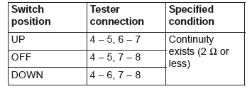
STEP 23. Check the rear power window sub switch (RH) for continuity.
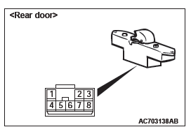
- Remove the rear power window sub switch (RH). Refer to GROUP 42A, Door, Door Glass and Regulator.
- Check continuity when the rear power window sub switch (RH) is operated to "UP" or "DOWN" position.
Q: Is the rear power window sub switch (RH) normal? YES : Go to Step 24.
NO : Replace the rear power window sub switch (RH).
When the rear power window sub switch (RH) is operated, the rear power window (RH) should raise and lower normally.
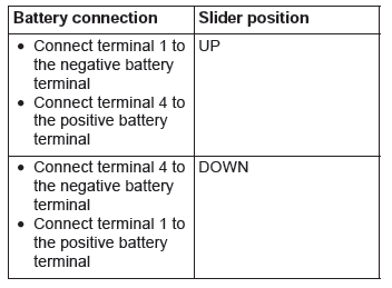
STEP 24. Check the rear power window motor (RH).
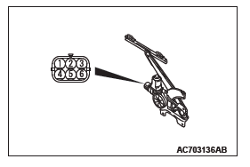
- Remove the rear power window regulator assembly (RH).
Refer to GROUP 42A, Door, Door Glass and Regulator.
- Connect a battery to the motor terminal, and check that the motor runs freely.
Q: Is the rear power window motor (RH) normal?
YES : Go to Step 25.
NO : Replace the rear power window motor (RH). When the rear power window sub switch (RH) is operated, the rear power window (RH) should raise and lower normally.
STEP 25. Check the battery power supply circuit to the rear power window sub switch (RH). Measure the voltage at rear power window sub switch (RH) connector E-11.
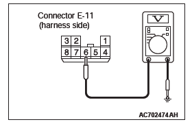
- Disconnect rear power window sub switch (RH) connector E-11 and measure the voltage available at the wiring harness side of the connector.
- Measure the voltage between terminal 6 and ground.
- The voltage should measure approximately 12 volts (battery positive voltage).
Q: Is the measured voltage approximately 12 volts (battery positive voltage)?
YES : Go to Step 28.
NO : Go to Step 26.
STEP 26. Check ETACS-ECU connector C-311 for loose, corroded or damaged terminals, or terminals pushed back in the connector.
Q: Is ETACS-ECU connector C-311 in good condition?
YES : Go to Step 27.
NO : Repair or replace the damaged component(s). Refer to GROUP 00E, Harness Connector Inspection. When the rear power window sub switch (RH) is operated, the rear power window (RH) should raise and lower normally.
STEP 27. Check the wiring harness between ETACS-ECU connector C-311 (terminal 12) and rear power window sub switch (RH) connector E-11 (terminal 6).
- Check the power supply line for open circuit and short circuit.
NOTE: Also check intermediate connectors D-36. If intermediate connector D-36 is damaged, repair or replace the connector as described in GROUP 00E, Harness Connector Inspection.
Q: Is the wiring harness between ETACS-ECU connector C-311 (terminal 12) and rear power window sub switch (RH) connector E-11 (terminal 6) in good condition?
YES : No action is necessary and testing is complete.
NO : The wiring harness may be damaged or the connector(s) may have loose, corroded or damaged terminals, or terminals pushed back in the connector.
Repair the wiring harness as necessary. When the rear power window sub switch (RH) is operated, the rear power window (RH) should raise and lower normally.
STEP 28. Check the ground circuit to the rear power window sub switch (RH). Measure the resistance at rear power window sub switch (RH) connector E-11.
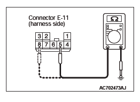
- Disconnect rear power window sub switch (RH) connector E-11 and measure the resistance available at the wiring harness side of the connector.
- Measure the resistance value between terminal 5 and ground, and also between terminal 8 and ground.
- The resistance should be 2 ohms or less.
Q: Is the measured resistance 2 ohms or less?
YES : Go to Step 30.
NO : Go to Step 29.
STEP 29. Check the wiring harness between power window main switch connector E-19 (terminals 15, 17) and rear power window sub switch (RH) connector E-11 (terminals 5, 8).
- Check the power supply lines for open circuit and short circuit.
NOTE: Also check intermediate connectors C-20, C-126 and D-36. If intermediate connector C-20, C-126 or D-36 is damaged, repair or replace the damaged component(s) as described in GROUP 00E, Harness Connector Inspection.
Q: Is the wiring harness between power window main switch connector E-19 (terminals 15, 17) and rear power window sub switch (RH) connector E-11 (terminals 5, 8) in good condition?
YES : Replace the power window main switch. When the rear power window sub switch (RH) is operated, the rear power window (RH) should raise and lower normally.
NO : The wiring harness may be damaged or the connector(s) may have loose, corroded or damaged terminals, or terminals pushed back in the connector.
Repair the wiring harness as necessary. When the rear power window sub switch (RH) is operated, the rear power window (RH) should raise and lower normally.
STEP 30. Check the wiring harness between rear power window sub switch (RH) connector E-11 (terminals 4, 7) and rear power window motor (RH) connector E-12 (terminals 4, 1).
- Check the power supply lines for open circuit and short circuit.
Q: Is the wiring harness between rear power window sub switch (RH) connector E-11 (terminals 4, 7) and rear power window motor (RH) connector E-12 (terminals 4, 1) in good condition?
YES : No action is necessary and testing is complete.
NO : The wiring harness may be damaged or the connector(s) may have loose, corroded or damaged terminals, or terminals pushed back in the connector.
Repair the wiring harness as necessary. When the rear power window sub switch (RH) is operated, the rear power window (RH) should raise and lower normally.
INSPECTION PROCEDURE C-4: Front and/or Rear Passenger's Power Window(s) do not work by means of the Power Window Main Switch.
CAUTION Before replacing the ECU, ensure that the power supply circuit, the ground circuit and the communication circuit are normal.
Power window (Front Passenger's side) Circuit
Power window (Rear Door) Circuit
CIRCUIT OPERATION
If the front passenger's and/or rear power window does not work by means of the power window main switch, the power window main switch or the respective power window sub switch(es) may be defective.
TECHNICAL DESCRIPTION (COMMENT)
If the corresponding power window opens and closes normally when each power window sub-switch is operated, the power window main switch may be defective.
TROUBLESHOOTING HINT
- The power window main switch may be defective
- The front power window sub switch may be defective
- The rear power window sub switches may be defective
- The wiring harness or connectors may have loose, corroded, or damaged terminals, or terminals pushed back in the connector
DIAGNOSTIC PROCEDURE
STEP 1. Check the power window main switch.
Check that the driver's power window works by means of the power window main switch.
Q: Is the power window main switch in good condition?
YES : Go to Step 2.
NO : Refer to inspection procedure 2 "Driver's power window does not work by means of the power window main switch".
STEP 2. Check the power window sub switches.
Check that each power window works by means of the respective power window sub switch when the power window lock switch is turned off.
Q: Are the power window sub switches in good condition when the power window lock switch is turned off?
YES : Go to Step 3.
NO : Refer to inspection procedure 3 "Relevant power window(s) does not work by means of the front and rear passenger's power window sub switches".
STEP 3. Determine a trouble spot.
Q: Which power window does not work?
Front passenger's door : Go to Step 4.
Rear right door : Go to Step 7.
Rear left door : Go to Step 10.
STEP 4. Check power window main switch E-19 and front power window sub switch connector E-06 for loose, corroded or damaged terminals, or terminals pushed back in the connector.
Q: Are front power window main switch connector E-19 and front power window sub switch connector E-06 in good condition?
YES : Go to Step 5.
NO : Repair or replace the damaged component(s). Refer to GROUP 00E, Harness Connector Inspection.
STEP 5. Check the wiring harness between power window main switch connector E-19 (terminals 1, 3) and front power window sub switch connector E-06 (terminals 8, 5).
- Check the signal line for open circuit and short circuit.
NOTE: Also check intermediate connector C-112, C-126. If intermediate connector C-112, C-126 is damaged, repair or replace the damaged component( s) as described in GROUP 00E, Harness Connector Inspection.
Q: Is the wiring harness between power window main switch connector E-19 (terminals 1, 3) and front power window sub switch connector E-06 (terminals 8, 5) in good condition?
YES : Go to Step 6.
NO : The wiring harness may be damaged or the connector(s) may have loose, corroded or damaged terminals, or terminals pushed back in the connector. Repair the wiring harness as necessary.
STEP 6. Retest the system.
- Replace the front passenger's power window sub switch.
- Check that the front passenger's power window works by means of the power window main switch.
Q: Is the front passenger's power window sub switch in good condition?
YES : No action is necessary and testing is complete.
NO : Replace the power window main switch.
STEP 7. Check power window main switch E-19 and rear power window sub switch (RH) connector E-11 for loose, corroded or damaged terminals, or terminals pushed back in the connector.
Q: Are front power window main switch connector E-19 and rear power window sub switch (RH) connector E-11 in good condition?
YES : Go to Step 8.
NO : Repair or replace the damaged component(s). Refer to GROUP 00E, Harness Connector Inspection.
STEP 8. Check the wiring harness between power window main switch connector E-19 (terminals 15, 17) and rear power window sub switch (RH) connector E-11 (terminals 5, 8).
- Check the signal line for open circuit and short circuit.
NOTE: Also check intermediate connector C-20, D-36. If intermediate connector C-20, D-36 is damaged, repair or replace the damaged component(s) as described in GROUP 00E, Harness Connector Inspection.
Q: Is the wiring harness between power window main switch connector E-19 (terminals 15, 17) and rear power window sub switch (RH) connector E-11 (terminals 5, 8) in good condition?
YES : Go to Step 9.
NO : The wiring harness may be damaged or the connector(s) may have loose, corroded or damaged terminals, or terminals pushed back in the connector. Repair the wiring harness as necessary.
STEP 9. Retest the system.
- Replace the rear power window sub switch (RH).
- Check that rear power window (RH) works by means of the power window main switch.
Q: Is the rear power window sub switch (RH) in good condition?
YES : No action is necessary and testing is complete.
NO : Replace the power window main switch.
STEP 10. Check power window main switch E-19 and rear power window sub switch (LH) connector E-25 for loose, corroded or damaged terminals, or terminals pushed back in the connector.
Q: Is front power window main switch connector E-19 and rear power window sub switch (LH) connector E-25 in good condition?
YES : Go to Step 11.
NO : Repair or replace the damaged component(s). Refer to GROUP 00E, Harness Connector Inspection.
STEP 11. Check the wiring harness between power window main switch connector E-19 (terminals 18, 19) and rear power window sub switch (LH) connector E-25 (terminals 5, 8).
- Check the signal line for open circuit and short circuit.
NOTE: Also check intermediate connector C-32, D-21. If intermediate connector C-32, D-21 is damaged, repair or replace the damaged component(s) as described in GROUP 00E, Harness Connector Inspection.
Q: Is the wiring harness between power window main switch connector E-19 (terminals 18, 19) and rear power window sub switch (lH) connector E-25 (terminals 5, 8) in good condition?
YES : Go to Step 12.
NO : The wiring harness may be damaged or the connector(s) may have loose, corroded or damaged terminals, or terminals pushed back in the connector. Repair the wiring harness as necessary.
STEP 12. Retest the system.
- Replace the rear power window sub switch (LH).
- Check that rear power window (LH) works by means of the power window main switch.
Q: Is the rear power window sub switch (LH) in good condition?
YES : No action is necessary and testing is complete.
NO : Replace the power window main switch.
INSPECTION PROCEDURE C-5: The Power Window Timer Function does not Work Normally.
CAUTION Before replacing the ECU, ensure that the power supply circuit, the ground circuit and the communication circuit are normal.
COMMENTS ON TROUBLE SYMPTOM
If the power window timer function does not work normally, a malfunction of the power window main switch or ETACS-ECU is suspected.
PROBABLE CAUSES
- Malfunction of the driver's door switch
- Malfunction of the front passenger's door switch
- Malfunction of the power window main switch
- Malfunction of ETACS-ECU
- Damaged wiring harness and connectors
DIAGNOSTIC PROCEDURE
Required Special Tools:
- MB992006: Extra fine probe
- MB991223: Harness set
- MB991958: Scan Tool (M.U.T.-III Sub Assembly)
- MB991824: Vehicles Communication Interface (V.C.I.)
- MB991827: M.U.T.-III USB Cable
- MB991910: M.U.T.-III Main Harness A
STEP 1. Check the power supply system.
With the ignition switch in the LOCK (OFF) position, check if the following function operates normally:
- Hazard warning lamp
Q: Is the check result normal?
YES : Go to Step 2.
NO : Refer to GROUP 54A − Malfunction of ETACS-ECU power supply circuit.
STEP 2. Using scan tool MB991958, check data list.
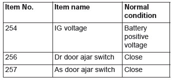
Check the signals related to the power window timer function operation.
CAUTION To prevent damage to scan tool MB991958, always turn the ignition switch to the "LOCK" (OFF) position before connecting or disconnecting scan tool MB991958.
- Connect scan tool MB991958. Refer to "How to connect scan tool (M.U.T.-III)".
- Turn the ignition switch to the "ON" position.
- Check the data list of the ETACS.
- Turn the ignition switch to the LOCK (OFF) position.
- Close the driver's door.
- Close the front passenger's door.
- Turn the ignition switch to the "LOCK" (OFF) position.
OK: Normal condition is displayed.
Q: Is the check result normal?
YES <Normal conditions are displayed for all the items.> : Go to Step 3.
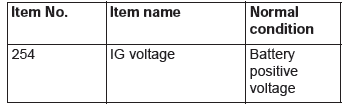
NO <Normal condition is not displayed for item No.254.> : Refer to GROUP 54A − Inspection procedure 2: "The ignition switch (IG1) signal is not received.
NO <Normal condition is not displayed for item No.256.> : Refer to GROUP 54A − Inspection procedure 5: "The front door switch (driver's side) signal is not received".
NO <Normal condition is not displayed for item No.257.> : Refer to GROUP 54A − Inspection procedure 6: the front door switch (passenger's side) signal is not received.
STEP 3. Retest the system.
Check that the power window timer function works normally.
Q: Is the check result normal?
YES : No action is necessary and testing is complete.
NO : Replace the power window main switch. Check that the power window timer function works normally.
INSPECTION PROCEDURE C-6: Power Window Anti-trap Function does not Work Normally <Driver's Side Only>.
CAUTION Before replacing the ECU, ensure that the input and output signal circuits are normal.
Driver's Power Window Circuit
CIRCUIT OPERATION
Malfunction of the power window motor revolution detection sensor is suspected.
TROUBLESHOOTING HINTS
- Malfunction of the power window motor
- Damaged wiring harness and connectors
DIAGNOSTIC PROCEDURE
Required Special Tools:
- MB992006: Extra fine probe
- MB991223: Harness set
- MB991958: Scan Tool (M.U.T.-III Sub Assembly)
- MB991824: Vehicles Communication Interface (V.C.I.)
- MB991827: M.U.T.-III USB Cable
- MB991910: M.U.T.-III Main Harness A
STEP 1. Using scan tool MB991958, read the diagnostic trouble code.
CAUTION To prevent damage to scan tool MB991958, always turn the ignition switch to the "LOCK" (OFF) position before connecting or disconnecting scan tool MB991958.
- Connect scan tool MB991958. Refer to "How to connect scan tool (M.U.T.-III)".
- Turn the ignition switch to the "ON" position.
- Check whether the power window main switch related DTC is set.
- Turn the ignition switch to the "LOCK" (OFF) position.
Q: Is the DTC set?
YES : Diagnose the power window main switch. Refer to Diagnostic trouble code chart.
NO : Go to Step 2.
STEP 2. Check the power window operating current.
Check that the power window operating current is normal.
Q: Is the check result normal?
YES : Door window glass adjustment.
Then go to Step 3.
NO : Replace the power window motor. Verify that the power window anti-trap function works normally.
STEP 3. Confirm the power window learning function.
Check that the power window switch has learned the fully closed position of the windows.
Q: Is the check result normal?
YES : Go to Step 4.
NO : Make the power window switch learn the fully closed position of the windows. Verify that the power window anti-trap function works normally.
STEP 4. Check power window main switch connector E-19, front power window motor (LH) connector E-16 for loose, corroded or damaged terminals, or terminals pushed back in the connector.
Q: Are power window main switch connector E-19, front power window motor (LH) connector E-16 in good condition?
YES : Go to Step 5.
NO : Repair or replace the damaged component(s). Refer to GROUP 00E, Harness Connector Inspection. Verify that the power window anti-trap function works normally.
STEP 5. Check the wiring harness between power window main switch connector E-19 (terminals 8, 9, 11, 12) and front power window motor (LH) connector E-16 (terminals 3, 5, 2, 6).
- Check the power supply lines for open circuit and short circuit.
Q: Is the wiring harness between power window main switch connector E-19 (terminals 8, 9, 11, 12) and front power window motor (LH) connector E-16 (terminals 3, 5, 2, 6) in good condition?
YES : Go to Step 6.
NO : The wiring harness may be damaged or the connector(s) may have loose, corroded or damaged terminals, or terminals pushed back in the connector.
Repair the wiring harness as necessary. Verify that the power window anti-trap function works normally.
STEP 6. Retest the system.
Check that the power window anti-trap function works normally.
Q: Is the check result normal?
YES : Intermittent malfunction (Refer to GROUP 00 − How to Use Troubleshooting/Inspection Service Points - How to Cope with Intermittent Malfunction).
NO : Replace the front power window motor (LH). Verify that the power window anti-trap function works normally.
INSPECTION PROCEDURE B-7: Window Glass Lowers Automatically while it is Rising <Driver's Side Only>.
CIRCUIT OPERATION
If the sliding resistance is too great when the window is being raised or the window glass encounters an object, the window glass will lower by approximately 150 mm (5.9 in).
TROUBLESHOOTING HINTS
- Improperly adjusted door window glass
- Incorrectly installed or warped glass slider
- Malfunction of the power window motor
- Malfunction of the window regulator
DIAGNOSIS
STEP 1. Check the power window anti-trap function.
Check that the power window anti-trap function works normally.
Q: Is the check result normal?
YES : Go to Step 2.
NO : Refer to P.42A.
STEP 2. Check that the door window glasses are installed correctly.
Check that the door window glasses are installed correctly.
Q: Is the check result normal?
YES : Go to Step 3.
NO : Adjust the door window glass.
Verify that the power window works normally.
STEP 3. Retest the system.
Check that the power window does not lower while it is being raised.
Q: Is the check result normal?
YES : No action is necessary and testing is complete.
NO : Replace the power window motor of the defective window. Verify that the power window works normally.
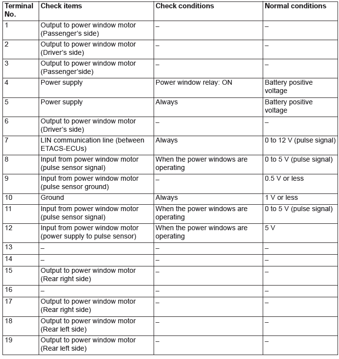
CHECK AT ECU TERMINAL
POWER WINDOW SWITCH TERMINAL CHECK
POWER WINDOW MAIN SWITCH

READ NEXT:
 Door Diagnosis
INTRODUCTION TO GLASS AND DOOR DIAGNOSIS
Glass and door faults include water leaks and
improper opening and closing. Causes for these
faults can include faults in the glass, weatherstrip,
drain hole o
On-vehicle Service
DOOR FIT ADJUSTMENT
Required Special Tools:
MB990211: Slide Hammer
MB990243: Body Puller
MB990900 or MB991164: Door Adjusting Wrench
MB990939: Brass Bar
CAUTION
Do not rotate special tool MB9
Door Assembly, Door Glass and Regulator, Door Handle and Latch
Door Assembly
REMOVAL AND INSTALLATION
Post-installation operation
Door adjustment
<Front door>
Damper removal
Damper
Door assembly and front door
hinge removal steps
Front scuff plate,
SEE MORE:
Front Axle
General Information
For the front axle, the unit ball bearing (double-row
angular contact ball bearing) with an integral oil seal
is used as a wheel bearing, and EBJ-PTJ type constant
velocity joint as a driveshaft.
It has the following features:
The driveshaft incorporates EBJ-PTJ type constant
Bonnet
To open
1. Pull the release lever toward you to unlock the bonnet.
2. Raise the bonnet while pressing the safety lock.
NOTE:
● Only open the bonnet when the wipers are in the parked position. In any other
position, the wipers could damage the paint or bonnet.
3. Support the bonnet
