Mitsubishi Outlander: Diagnosis
STANDARD FLOW OF DIAGNOSTIC TROUBLESHOOTING
Refer to GROUP 00 − How to Use Troubleshooting/Inspection Service Points, Contents of Troubleshooting.
DIAGNOSTIC FUNCTION
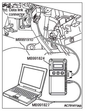
HOW TO CONNECT THE SCAN TOOL (M.U.T.-III)
Required Special Tools:
- MB991958: Scan Tool (M.U.T.-III Sub Assembly)
- MB991824: Vehicle Communication Interface (V.C.I.)
- MB991827: M.U.T.-III USB Cable
- MB991910: M.U.T.-III Main Harness A (Vehicles with CAN communication system)
CAUTION To prevent damage to scan tool MB991958, always turn the ignition switch to the "LOCK" (OFF) position before connecting or disconnecting scan tool MB991958.
1. Ensure that the ignition switch is at the "LOCK" (OFF) position.
2. Start up the personal computer.
3. Connect special tool MB991827 to special tool MB991824 and the personal computer.
4. Connect special tool MB991910 to special tool MB991824.
5. Connect special tool MB991910 to the data link connector.
6. Turn the power switch of special tool MB991824 to the "ON" position.
NOTE: When special tool MB991824 is energized, special tool MB991824 indicator light will be illuminated in a green color.
7. Start the M.U.T.-III system on the personal computer.
NOTE: Disconnecting scan tool MB991958 is the reverse of the connecting sequence, making sure that the ignition switch is at the "LOCK" (OFF) position.
HOW TO READ AND ERASE DIAGNOSTIC TROUBLE CODES
Required Special Tools:
- MB991958: Scan Tool (M.U.T.-III Sub Assembly)
- MB991824: Vehicle Communication Interface (V.C.I.)
- MB991827: M.U.T.-III USB Cable
- MB991910: M.U.T.-III Main Harness A (Vehicles with CAN communication system)
CAUTION To prevent damage to scan tool MB991958, always turn the ignition switch to the "LOCK" (OFF) position before connecting or disconnecting scan tool MB991958.
NOTE: If the battery voltage is low, diagnostic trouble codes will not be set. Check the battery if scan tool MB991958 does not display.
1. Connect scan tool MB991958 to the data link connector.
2. Turn the ignition switch to the "ON" position.
3. Select "System select" from the start-up screen.
4. Select "From 2006 MY" of "Model Year". When the "Vehicle Information" is displayed, check the contents.
5. Select "WCM" from "System List", and press the "OK" button.
NOTE: When the "Loading Option Setup" list is displayed, check the applicable item.
6. Select "Diagnostic Trouble Code". to read the DTC.
7. If a DTC is set, it is shown.
8. Choose "Erase DTCs" to erase the DTC.
CHECK OF FREEZE FRAME DATA
The freeze frame data can be checked by using the scan tool.
When detecting fault and storing the DTC, the ECU connected to CAN bus line obtains the data before the determination of the DTC and the data when the DTC is determined, and then stores the ECU status of that time. By analyzing each data from scan tool, the troubleshooting can be performed more efficiently.
The displayed items are as the table below.
DISPLAY ITEM LIST
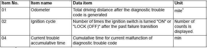
NOTE: *: If a failure occurs to both the ABS-ECU and ETACS-ECU, 0000 mile or FFFF mile is displayed to the scan tool MB991958.
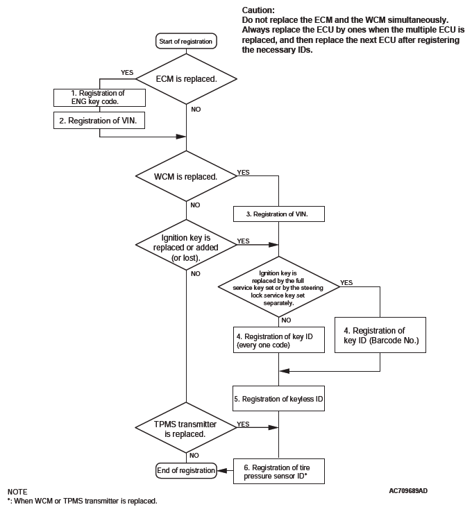
ID CODES REGISTRATION JUDGMENT TABLE
CAUTION Do not replace the engine control module (ECM) and WCM at the same time. When replacing several ECUs, always replace one ECU at a time, register the necessary IDs in it, and then replace the next ECU.
The transponder (a small transmitter) in the ignition key, WCM, and the ECM have their own ID codes stored in them. When the cases listed in the table below occur, the ID codes must be registered in the WCM or ECM again.
NOTE: Up to eight ignition keys (key ID and keyless entry secret code) can be stored in the memory of WCM.
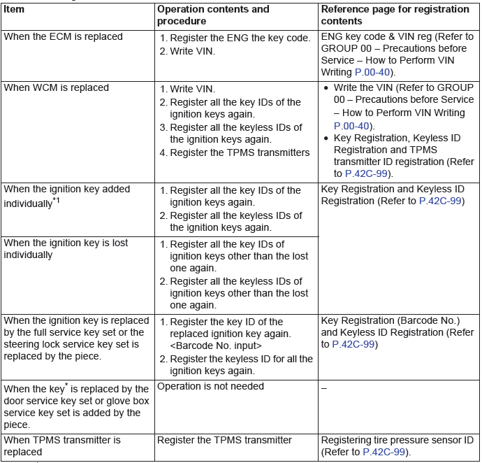
NOTE: *: Key (the key that can be used to lock/unlock the door or glove box only)
NOTE: *1: When available, key registration should be done beginning with a key that has been registered.
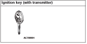
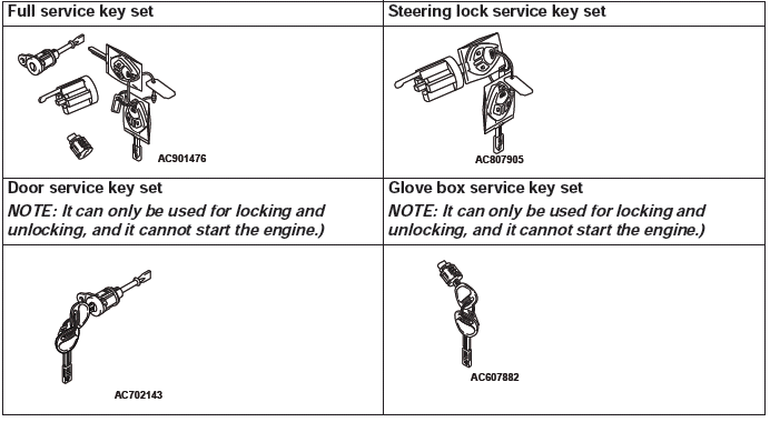
SUPPLY UNIT LIST FOR INDIVIDUAL KEY
KEY SUPPLY UNIT LIST FOR OTHER THAN INDIVIDUAL KEY
Registration flow chart
WARNINGS/ALARMS <VEHICLES WITHOUT COLOR LIQUID CRYSTAL DISPLAY>
If the TPMS fails or the tire pressure is low, the WCM warns the driver of that state by the TPMS warning light and the multi information display in the combination meter.
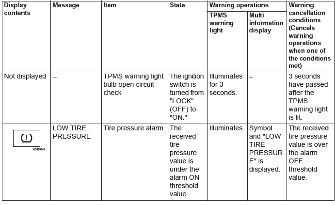
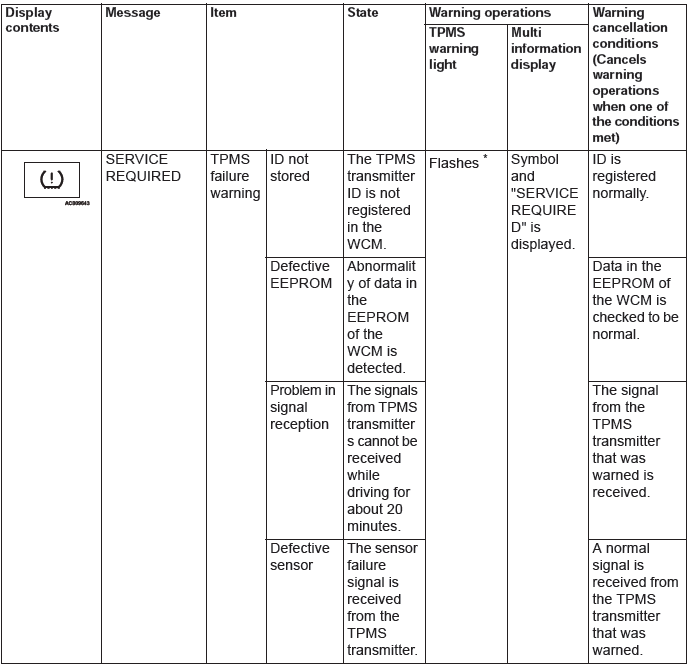
NOTE: *: Change to continuous illumination after flashing for about 1 minute.
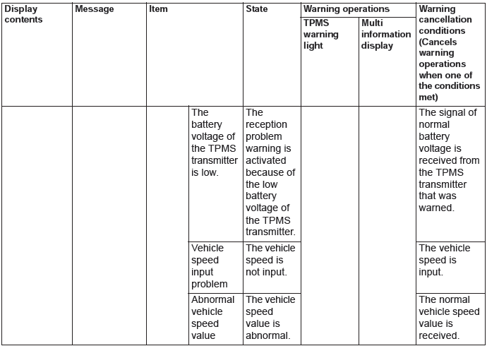
WARNINGS/ALARMS <VEHICLES WITH COLOR LIQUID CRYSTAL DISPLAY>
If the TPMS fails or the tire pressure is low, the WCM warns the driver of that state by the TPMS warning light and the multi information display in the combination meter.
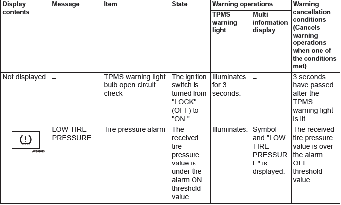


NOTE: *: Change to continuous illumination after flashing for about 1 minute.
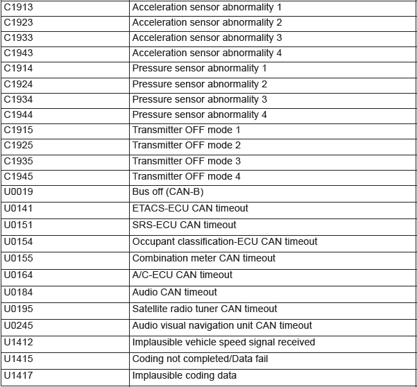
DIAGNOSTIC TROUBLE CODE CHART
CAUTION During diagnosis, a DTC associated with other system may be set when the ignition switch is turned on with connector(s) disconnected. On completion, confirm all systems for DTC(s). If DTC(s) are set, erase them all.
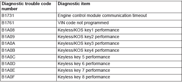
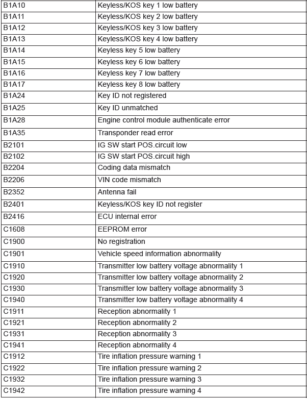
- DTC B1731, B1761, B1A08, B1A09, B1A0A, B1A0B, B1A0C, B1A0D, B1A0E, B1A0F, B1A10, B1A11, B1A12, B1A13, B1A14, B1A15, B1A16, B1A17, B1A24, B1A25, B1A28, B1A35, B2101, B2102
- DTC B2204, B2206, B2352, B2416, C1608, C1910, C1920, C1930, C1940, C1911, C1921, C1931, C1941, C1912, C1922, C1932, C1942, C1913, C1923, C1933, C1943, C1914, C1924, C1934, C1944
- DTC C1915, C1925, C1935, C1945, U0019, U0141, U0151, U0154, U0155, U0164, U0184, U0195, U0245, U1412 , U1415, U1417
- Inspection Procedure
READ NEXT:
 DTC B1731, B1761, B1A08, B1A09, B1A0A, B1A0B, B1A0C, B1A0D, B1A0E, B1A0F,
B1A10, B1A11, B1A12, B1A13, B1A14, B1A15, B1A16, B1A17, B1A24, B1A25, B1A28,
B1A35, B2101, B2102
DTC B1731, B1761, B1A08, B1A09, B1A0A, B1A0B, B1A0C, B1A0D, B1A0E, B1A0F,
B1A10, B1A11, B1A12, B1A13, B1A14, B1A15, B1A16, B1A17, B1A24, B1A25, B1A28,
B1A35, B2101, B2102
DTC B1731: Engine control module communication timeout
CAUTION
When the DTC B1731 is set, be sure to diagnose
the CAN bus line.
When replacing the ECU, always check that
the communication circuit
DTC B2204, B2206, B2352, B2416, C1608, C1910, C1920, C1930, C1940, C1911,
C1921, C1931, C1941, C1912, C1922, C1932, C1942, C1913, C1923, C1933, C1943,
C1914, C1924, C1934, C1944
DTC B2204: Coding data mismatch
CAUTION
When DTC B2204 is set, be sure to diagnose
the CAN bus line.
When replacing the ECU, always check that
the communication circuit is normal.
DTC SET CONDIT
DTC C1915, C1925, C1935, C1945, U0019, U0141, U0151, U0154, U0155, U0164, U0184,
U0195, U0245, U1412 , U1415, U1417
DTC C1915: Transmitter OFF mode 1
DTC C1925: Transmitter OFF mode 2
DTC C1935: Transmitter OFF mode 3
DTC C1945: Transmitter OFF mode 4
CAUTION
If there is any problem in the CAN bus lines, an incorre
SEE MORE:
General Information
CENTRAL DOOR LOCKING SYSTEM
The central door locking system operates the door
lock actuator to lock or unlock the doors and liftgate
using the door lock switch built into the front power
window (main or sub RH) switch. The system has the
following operations and features:
All doors and liftgate ca
Local Interconnect Network (LIN)
General Information
LIN refers to "Local Interconnect Network," which is a
serial multiplex communication protocol* administrated
by LIN consortium. A communication circuit
employing the LIN protocol connects each ECU, and
switch and sensor data can be shared among ECUs,
which enables more reduction
