Mitsubishi Outlander: DTC C2104, C1073, C2116, C1000, C2200, C2100, C2101, C1395, C2203, C1608, U0001, U0100, U0141, U1415, U1417
DTC C2104 Faulty valve power supply circuit
Power Supply Circuit
CAUTION If there is any problem in the CAN bus lines, an incorrect DTC may be set. Prior to this diagnosis, diagnose the CAN bus lines (Refer to GROUP 54C − CAN Bus Line Diagnostic Flow).
OPERATION
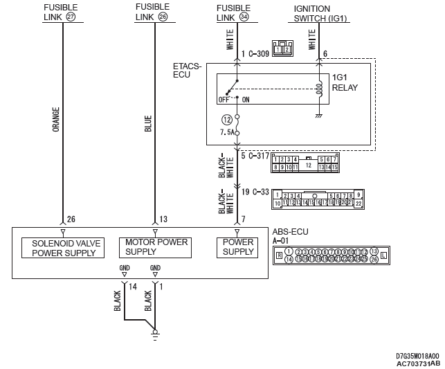
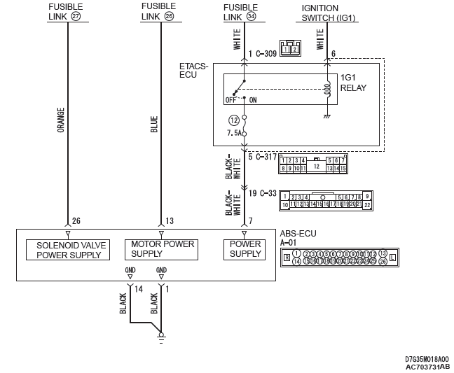
- ABS-ECU contains the power supply circuit (terminal No.26) for the solenoid valve. The solenoid valve is energized by the valve relay, which is incorporated in ABS-ECU.
- The valve relay, which is incorporated in ABS-ECU, is always energizing the solenoid valve unless the initial check is in progress when the ignition switch is turned on, or the recurrent system check is in progress.
DTC SET CONDITIONS
This DTC will be set when the solenoid valve supply voltage is not within the standard value.
PROBABLE CAUSES
Current trouble
- Fusible link malfunction
- Damaged wiring harness and connectors
- Abnormality in battery or generator
- ABS-ECU malfunction
Past trouble
- Carry out diagnosis with particular emphasis on wiring harness and connector failures between the power supply circuit (terminal No.26) to ABS-ECU solenoid valve or ground circuit (terminal No.14). For diagnosis procedures, refer to How to treat past trouble (GROUP 00 − How to Use Troubleshooting/ How to Treat Past Trouble).
DIAGNOSIS
Required Special Tools:
- MB991958: Scan Tool (M.U.T.-III Sub Assembly)
- MB991824: Vehicle Communication Interface (V.C.I.)
- MB991827: M.U.T.-III USB Cable
- MB991910: M.U.T.-III Main Harness A
- MB991974: ABS check harness
STEP 1. Using scan tool MB991958, diagnose the CAN bus line.
Use scan tool MB991958 to diagnose the CAN bus lines.
Q: Is the check result normal?
YES : Go to Step 3.
NO : Repair the CAN bus lines (Refer to GROUP 54C − CAN Bus Diagnostics Table). On completion, go to Step 2.
STEP 2. DTC recheck after resetting CAN bus lines
Q: Is the DTC C2104 set?
YES : Go to Step 3.
NO : The procedure is complete.
STEP 3. Battery check
Q: Is the battery in good condition?
YES : Go to Step 4.
NO : Replace the battery. Then go to Step 11.
STEP 4. Charging system check
Q: Is the charging system in good condition?
YES : Go to Step 5.
NO : Repair or replace the charging system component(s).
Then go to Step 11.
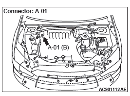
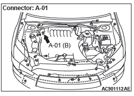
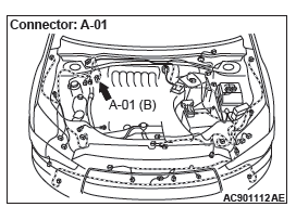
STEP 5. Connector check: A-01 ABS-ECU connector
Q: Is the check result normal?
YES : Go to Step 6.
NO : Repair the defective connector. Then go to Step 11.
STEP 6. Fusible link check: Check the fusible link No.27.
Visually check for open circuit in the fusible link No.27.
Q: Is the check result normal?
YES : Go to Step 8.
NO : Go to Step 7.
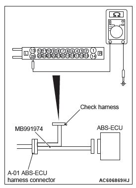
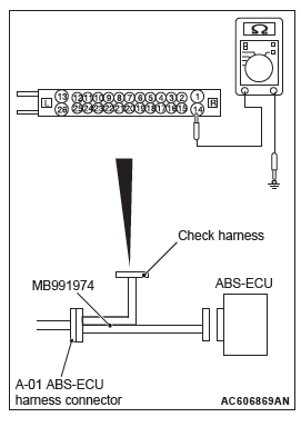
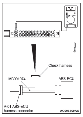
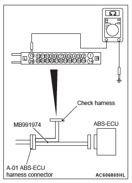
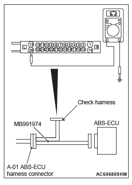
STEP 7. Resistance measurement at A-01 ABS-ECU connector
- Disconnect the ABS-ECU connector, connect special tool
ABS check harness (MB991974) to the harness-side
connector, and then measure the resistance at the special
tool connector side.
NOTE: Do not connect the special tool ABS check harness (MB991974) to ABS-ECU.
- Disconnect the fusible link No.27.
- Measure the resistance between the terminal No.26 and the
body ground.
OK: No continuity
Q: Is the check result normal?
YES : Replace the fusible link No.27. Then go to Step 11.
NO : The short circuit may be present in the power supply circuit. Repair the wiring harness between the A-01 ABS-ECU connector terminal No.26 and the fusible link No.27, and then replace the fusible link No.27.
Then go to Step 11.
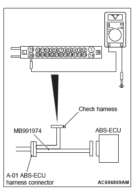
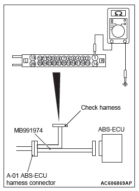
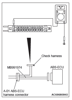
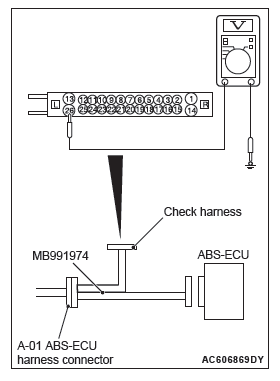
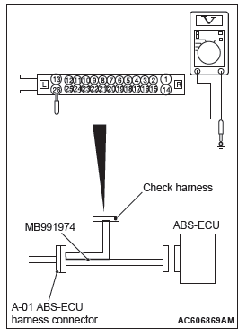
STEP 8. Voltage measurement at the A-01 ABS-ECU connector
- Disconnect the ABS-ECU connector, connect special tool
ABS check harness (MB991974) to the harness-side
connector, and then measure the resistance at the special
tool connector side.
NOTE: Do not connect the special tool ABS check harness (MB991974) to ABS-ECU.
- Measure the voltage between the terminal No.26 and the
body ground.
OK: Approximately system voltage
Q: Is the check result normal?
YES : Go to Step 9.
NO : The open circuit may be present in the power supply circuit. Repair the wiring harness between the A-01 ABS-ECU connector terminal No.26 and the fusible link No.27. Then go to Step 11.
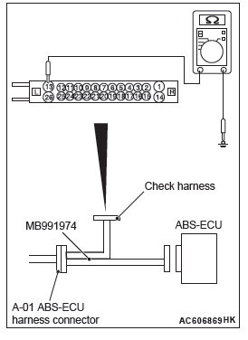
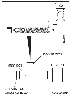
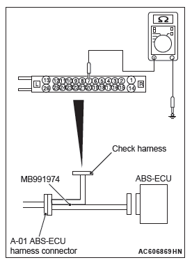
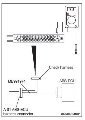
STEP 9. Resistance measurement at A-01 ABS-ECU connector
- Disconnect the ABS-ECU connector, connect special tool
ABS check harness (MB991974) to the harness-side
connector, and then measure the resistance at the special
tool connector side.
NOTE: Do not connect the special tool ABS check harness (MB991974) to ABS-ECU.
- Measure the resistance between the terminal No.1 and the body ground, and between the terminal No.14 and the body ground OK: Continuity exists (2 Ω or less)
Q: Is the check result normal?
YES : Go to Step 10.
NO : An open circuit may be present in the ground circuit.
Repair the wiring harness between the A-01 ABS-ECU connector terminal No.1 and the body ground, and between the A-01 ABS-ECU connector terminal No.14 and the body ground. Then go to Step 11.
STEP 10. Check whether the DTC is reset.
Erase the DTC.
Q: Is the DTC C2104 set?
YES : Replace the hydraulic unit (integrated with ABS-ECU). Then go to Step 11.
NO : Intermittent malfunction (Refer to GROUP 00 − How to Use Troubleshooting/How to Cope with Intermittent Malfunctions).
STEP 11. Check whether the DTC is reset.
Erase the DTC.
Q: Is the DTC C2104 set?
YES : Return to Step 1.
NO : The procedure is complete.
DTC C1073 Faulty motor drive circuit
Power Supply Circuit
CAUTION If there is any problem in the CAN bus lines, an incorrect DTC may be set. Prior to this diagnosis, diagnose the CAN bus lines (Refer to GROUP 54C − CAN Bus Line Diagnostic Flow).
OPERATION
- ABS-ECU contains the power supply circuit (terminal No.13) for the pump motor. The pump motor is energized by the motor switch, which is incorporated in ABS-ECU.
- The pump motor switch, which is incorporated in ABS-ECU, is always off unless the ABS operating or the motor solenoid valve check is activated when the vehicle is started.
- ABS-ECU activates the pump motor by turning on the ECU built-in pump motor switch.
DTC SET CONDITIONS
If the pump motor switch voltage drop indicates high value when the pump motor operates or after the operation, the pump motor operation is stopped and this DTC is set.
PROBABLE CAUSES
Current trouble
- Fusible link malfunction
- Damaged wiring harness and connectors
- Abnormality in battery or generator
- ABS-ECU malfunction
Past trouble
- Carry out diagnosis with particular emphasis on wiring harness and connector failures between the power supply circuit (A-01 ABS-ECU connector terminal No.13) to the ABS-ECU motor and the ground circuit (A-01 ABS-ECU connector terminal No.1). For diagnosis procedures, refer to How to treat past trouble (GROUP 00 − How to Use Troubleshooting/ How to Treat Past Trouble).
DIAGNOSIS
Required Special Tools:
- MB991958: Scan Tool (M.U.T.-III Sub Assembly)
- MB991824: Vehicle Communication Interface (V.C.I.)
- MB991827: M.U.T.-III USB Cable
- MB991910: M.U.T.-III Main Harness A
- MB991974: ABS check harness
STEP 1. Using scan tool MB991958, diagnose the CAN bus line.
Use scan tool MB991958 to diagnose the CAN bus lines.
Q: Is the check result normal?
YES : Go to Step 3.
NO : Repair the CAN bus lines (Refer to GROUP 54C − CAN Bus Diagnostics Table). On completion, go to Step 2.
STEP 2. Check whether the DTC is reset.
Q: Is the DTC C1073 set?
YES : Go to Step 3.
NO : The procedure is complete.
STEP 3. Battery check
Q: Is the battery in good condition?
YES : Go to Step 4.
NO : Replace the battery. Then go to Step 11.
STEP 4. Charging system check
Q: Is the charging system in good condition?
YES : Go to Step 5.
NO : Repair or replace the charging system component(s).
Then go to Step 11.
STEP 5. Connector check: A-01 ABS-ECU connector
Q: Is the check result normal?
YES : Go to Step 6.
NO : Repair the defective connector. Then go to Step 11.
STEP 6. Fusible link check: Check the fusible link No.26.
Visually check for open circuit in the fusible link No.26.
Q: Is the check result normal?
YES : Go to Step 8.
NO : Go to Step 7.
STEP 7. Resistance measurement at A-01 ABS-ECU connector
- Disconnect the ABS-ECU connector, connect special tool
ABS check harness (MB991974) to the harness-side
connector, and then measure the resistance at the special
tool connector side.
NOTE: Do not connect the special tool ABS check harness (MB991974) to ABS-ECU.
- Measure the resistance between the terminal No.13 and the
body ground.
OK: No continuity
Q: Is the check result normal?
YES : Replace the fusible link No.26. Then go to Step 11.
NO : The short circuit may be present in the power supply circuit. Repair the wiring harness between the A-01 ABS-ECU connector terminal No.13 and the fusible link No.26, and then replace the fusible link No.26.
Then go to Step 11.
STEP 8. Voltage measurement at the A-01 ABS-ECU connector
- Disconnect the ABS-ECU connector, connect special tool
ABS check harness (MB991974) to the harness-side
connector, and then measure the resistance at the special
tool connector side.
NOTE: Do not connect the special tool ABS check harness (MB991974) to ABS-ECU.
- Measure the voltage between the terminal No.13 and the
body ground.
OK: Approximately system voltage
Q: Is the check result normal?
YES : Go to Step 9.
NO : The open circuit may be present in the power supply circuit. Repair the wiring harness between the A-01 ABS-ECU connector terminal No.13 and the fusible link No.26. Then go to Step 11.
STEP 9. Resistance measurement at A-01 ABS-ECU connector
- Disconnect the ABS-ECU connector, connect special tool
ABS check harness (MB991974) to the harness-side
connector, and then measure the resistance at the special
tool connector side.
NOTE: Do not connect the special tool ABS check harness (MB991974) to ABS-ECU.
- Measure the resistance between the terminal No.1 and the body ground, and between the terminal No.14 and the body ground OK: Continuity exists (2 Ω or less)
Q: Is the check result normal?
YES : Go to Step 10.
NO : An open circuit may be present in the ground circuit.
Repair the wiring harness between the A-01 ASC-ECU connector terminal No.1 and the body ground, and between the A-01 ASC-ECU connector terminal No.14 and the body ground. Then go to Step 11.
STEP 10. Check whether the DTC is reset.
- Erase the DTC.
- Drive the vehicle at 12mph (20 km/h) or higher.
NOTE: The ABS warning light does not turn OFF in some cases unless the vehicle runs at 12mph (20 km/h) or higher.
Q: Is the DTC C1073 set?
YES : Replace the hydraulic unit (integrated with ABS-ECU). Then go to Step 11.
NO : Intermittent malfunction (Refer to GROUP 00 − How to Use Troubleshooting/How to Cope with Intermittent Malfunctions).
STEP 11. Check whether the DTC is reset.
- Erase the DTC.
- Drive the vehicle at 12mph (20 km/h) or higher.
NOTE: The ABS warning light does not turn OFF in some cases unless the vehicle runs at 12mph (20 km/h) or higher.
Q: Is the DTC C1073 set?
YES : Return to Step 1.
NO : The procedure is complete.
DTC C2116 Abnormality in power supply voltage in pump motor
Power Supply Circuit
CAUTION
- If there is any problem in the CAN bus lines, an incorrect DTC may be set. Prior to this diagnosis, diagnose the CAN bus lines.
- Whenever ECU is replaced, ensure that the CAN bus lines are normal.
OPERATION
- ABS-ECU contains the power supply circuit (terminal No.13) for the pump motor. The pump motor is energized by the motor switch, which is incorporated in ABS-ECU.
- The pump motor switch, which is incorporated in ABS-ECU, is always off unless the motor solenoid valve check is activated when the vehicle is started.
- ABS-ECU activates the pump motor by turning on the ECU built-in pump motor switch.
DTC SET CONDITIONS
This DTCs will be set under the cases below:
- When the power supply voltage of the pump motor, which is not in operation, is abnormally low for a prolonged period
- When the power supply voltage of the pump motor, which is not in operation, is abnormally high for a prolonged period
PROBABLE CAUSES
Current trouble
- Fusible link malfunction
- Damaged wiring harness and connectors
- Abnormality in battery or generator
- ABS-ECU malfunction
Past trouble
- Carry out diagnosis with particular emphasis on wiring harness and connector failures between the power supply circuit (A-01 ABS-ECU connector terminal No.13) to the ABS-ECU motor and the ground circuit (A-01 ABS-ECU connector terminal No.1). For diagnosis procedures, refer to How to treat past trouble (GROUP 00 − How to Use Troubleshooting/ How to Treat Past Trouble).
DIAGNOSIS
Required Special Tools:
- MB991958: Scan Tool (M.U.T.-III Sub Assembly)
- MB991824: Vehicle Communication Interface (V.C.I.)
- MB991827: M.U.T.-III USB Cable
- MB991910: M.U.T.-III Main Harness A
- MB991974: ABS check harness
STEP 1. Using scan tool MB991958, diagnose the CAN bus line.
Use scan tool MB991958 to diagnose the CAN bus lines.
Q: Is the check result normal?
YES : Go to Step 3.
NO : Repair the CAN bus lines. On completion, go to Step 2.
STEP 2. DTC recheck after resetting CAN bus lines
Q: Is the DTC C2116 set?
YES : Go to Step 3.
NO : The procedure is complete.
STEP 3. Battery check
Q: Is the battery in good condition?
YES : Go to Step 4.
NO : Replace the battery. Then go to Step 11.
STEP 4. Charging system check
Q: Is the charging system in good condition?
YES : Go to Step 5.
NO : Repair or replace the charging system component(s).
Then go to Step 11.
STEP 5. Connector check: A-01 ABS-ECU connector
Q: Is the check result normal?
YES : Go to Step 6.
NO : Repair the defective connector. Then go to Step 11.
STEP 6. Fusible link check: Check the fusible link No.26.
Visually check for open circuit in the fusible link No.26.
Q: Is the check result normal?
YES : Go to Step 8.
NO : Go to Step 7.
STEP 7. Resistance measurement at A-01 ABS-ECU connector
- Disconnect the ABS-ECU connector, connect special tool
ABS check harness (MB991974) to the harness-side
connector, and then measure the resistance at the special
tool connector side.
NOTE: Do not connect the special tool ABS check harness (MB991974) to ABS-ECU.
- Disconnect the fusible link No.26.
- Measure the resistance between the terminal No.13 and the
body ground.
OK: No continuity
Q: Is the check result normal?
YES : Replace the fusible link No.26. Then go to Step 11.
NO : The short circuit may be present in the power supply circuit. Repair the wiring harness between the A-08 ABS-ECU connector terminal No.13 and the fusible link No.26, and then replace the fusible link No.26.
Then go to Step 11.
STEP 8. Voltage measurement at the A-01 ABS-ECU connector
- Disconnect the ABS-ECU connector, connect special tool
ABS check harness (MB991974) to the harness-side
connector, and then measure the resistance at the special
tool connector side.
NOTE: Do not connect the special tool ABS check harness (MB991974) to ABS-ECU.
- Measure the voltage between the terminal No.13 and the
body ground.
OK: Approximately system voltage
Q: Is the check result normal?
YES : Go to Step 9.
NO : The open circuit may be present in the power supply circuit. Repair the wiring harness between the A-01 ABS-ECU connector terminal No.13 and the fusible link No.26. Then go to Step 11.
STEP 9. Resistance measurement at A-01 ABS-ECU connector
- Disconnect the ABS-ECU connector, connect special tool
ABS check harness (MB991974) to the harness-side
connector, and then measure the resistance at the special
tool connector side.
NOTE: Do not connect the special tool ABS check harness (MB991974) to ABS-ECU.
- Measure the resistance between the terminal No.1 and the
body ground, and between the terminal No.14 and the body
ground.
OK: Continuity exists (2 Ω or less)
Q: Is the check result normal?
YES : Go to Step 10.
NO : An open circuit may be present in the ground circuit.
Repair the wiring harness between the A-01 ABS-ECU connector terminal No.1 and the body ground, and between the A-01 ABS-ECU connector terminal No.14 and the body ground. Then go to Step 11.
STEP 10. Check whether the DTC is reset.
- Erase the DTC.
- Drive the vehicle at 12mph (20 km/h) or higher.
NOTE: The ABS warning light does not turn OFF in some cases unless the vehicle runs at 12mph (20 km/h) or higher.
Q: Is the DTC C2116 set?
YES : Replace the hydraulic unit (integrated with ABS-ECU). Then go to Step 11.
NO : Intermittent malfunction (Refer to GROUP 00 − How to Use Troubleshooting/How to Cope with Intermittent Malfunctions).
STEP 11. Check whether the DTC is reset.
- Erase the DTC.
- Drive the vehicle at 12mph (20 km/h) or higher.
NOTE: The ABS warning light does not turn OFF in some cases unless the vehicle runs at 12mph (20 km/h) or higher.
Q: Is the DTC C2116 set?
YES : Return to Step 1.
NO : The procedure is complete.
DTC C1000 Abnormality in stop light switch circuit
Stop Light Relay Circuit
CAUTION
- If there is any problem in the CAN bus lines, an incorrect DTC may be set. Prior to this diagnosis, diagnose the CAN bus lines (Refer to GROUP 54C − CAN Bus Line Diagnostic Flow).
- Whenever ECU is replaced, ensure that the CAN bus lines are normal.
OPERATION
ETACS-ECU sends the ON signal generated when the brake pedal is depressed and OFF signal generated when it is released to ABS-ECU via the CAN bus lines.
DTC SET CONDITIONS
This DTC is set in the following case.
- When the vehicle has run for a long time with the stoplight switch turned ON.
- When the OFF status of the stoplight switch does not match the vehicle attitude
PROBABLE CAUSES
- Malfunction of the stoplight relay
- Damaged wiring harness and connectors
- ETACS-ECU malfunction
- ABC-ECU malfunction
DIAGNOSIS
Required Special Tools:
- MB991958 Scan Tool (M.U.T.-III Sub Assembly)
- MB991824: Vehicle Communication Interface (V.C.I.)
- MB991827 M.U.T.-III USB Cable
- MB991910 M.U.T.-III Main Harness A
STEP 1. Check that the stoplight of the rear combination light illuminates normally.
Q: Is the check result normal?
YES : Go to Step 2.
NO : Diagnose the rear combination light (Refer to GROUP 54A − Rear Combination light/Trouble Symptom Chart). On completion, go to Step 2.
STEP 2. Using scan tool MB991958, diagnose the CAN bus lines.
Use M.U.T.-III to diagnose the CAN bus lines.
Q: Is the check result normal?
YES : Go to Step 4.
NO : Repair the CAN bus lines (Refer to GROUP 54C − CAN Bus Diagnostics Table). On completion, go to Step 3.
STEP 3. DTC recheck after resetting CAN bus lines
Q: Is DTC C1000 set?
YES : Go to Step 4.
NO : The procedure is complete.
STEP 4. Battery check
Q: Is the battery in good condition?
YES : Go to Step 5.
NO : Charge or replace the battery, and go to Step 10.
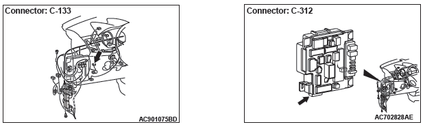
STEP 5. Connector check: C-312 ETACS-ECU connector
Q: Is the check result normal?
YES : Go to Step 6.
NO : Repair the damaged connector.
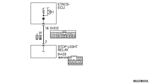
STEP 6. Measure the voltage at the C-312 ETACS-ECU connector.
- Measure by backprobing without disconnecting the ETACS-ECU connector and stoplight switch connector.
- Disconnecting the C-133 stoplight relay connector.
- Measure the voltage between the C-312 ETACS-ECU
connector terminal No.16 and the body ground.
OK:
When the brake pedal is released: Approximately 0 V − 5 V (pulse)
When the brake pedal is depressed: Approximately system voltage
Q: Is the check result normal?
YES : Go to Step 9.
NO : Go to Step 7.
STEP 7. Connector check: C-312 ETACS-ECU connector
Q: Is the check result normal?
YES : Go to Step 8.
NO : Repair the damaged connector.
STEP 8. Check the wiring harness between C-312 ETACS-ECU connector terminal No.16 and C-133 stoplight relay connector terminal No.2
- Check the signal line for open circuit.
Q: Is the check result normal?
YES : Go to Step 9.
NO : Replace the wiring harness.
STEP 9. Diagnostic trouble code recheck
Erase the DTC.
Q: Is diagnostic trouble code No.C1000 set?
YES : Replace the hydraulic unit (integrated with ABC-ECU). Then go to Step 10.
NO : Intermittent malfunction (Refer to GROUP 00 − How to Use Troubleshooting/How to Cope with Intermittent Malfunctions).
STEP 10. Diagnostic trouble code recheck
Erase the DTC.
Q: Is diagnostic trouble code No.C1000 set?
YES : Return to Step 1.
NO : The procedure is complete.
DTC C2200 Abnormality in ABS-ECU
CAUTION
- If there is any problem in the CAN bus lines, an incorrect DTC may be set. Prior to this diagnosis, diagnose the CAN bus lines (Refer to GROUP 54C − CAN Bus Line Diagnostic Flow).
- Whenever ECU is replaced, ensure that the CAN bus lines are normal.
OPERATION
ABS-ECU controls ABS by calculating the data sent from the wheel speed sensor and the G sensor.
DTC SET CONDITIONS
This DTC is set when ABS-ECU has malfunction.
PROBABLE CAUSES
ABS-ECU malfunction
DIAGNOSIS
Required Special Tools:
- MB991958: Scan Tool (M.U.T.-III Sub Assembly)
- MB991824: Vehicle Communication Interface (V.C.I.)
- MB991827: M.U.T.-III USB Cable
- MB991910: M.U.T.-III Main Harness A
STEP 1. Using scan tool MB991958, diagnose the CAN bus line.
Use scan tool MB991958 to diagnose the CAN bus lines.
Q: Is the check result normal?
YES : Go to Step 2.
NO : Repair the CAN bus lines (Refer to GROUP 54C − CAN Bus Diagnostics Table). On completion, go to Step 2.
STEP 2. DTC recheck after resetting CAN bus lines
Erase the DTC.
Q: Is the DTC C2200 set?
YES : Replace the hydraulic unit (integrated with ABS-ECU). Then go to Step 3.
NO : Intermittent malfunction (Refer to GROUP 00 − How to Use Troubleshooting/How to Cope with Intermittent Malfunctions).
STEP 3. DTC recheck after resetting CAN bus lines
Erase the DTC.
Q: Is the DTC C2200 set?
YES : Return to Step 1.
NO : This diagnosis is complete.
DTC C2100 Abnormality in battery voltage (low voltage)
ABS-ECU Power Supply Circuit
CAUTION
- If there is any problem in the CAN bus lines, an incorrect DTC may be set. Prior to this diagnosis, diagnose the CAN bus lines (Refer to GROUP 54C − CAN Bus Line Diagnostic Flow).
- Whenever ECU is replaced, ensure that the CAN bus lines are normal.
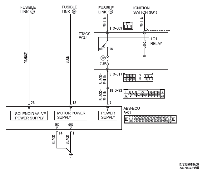
OPERATION
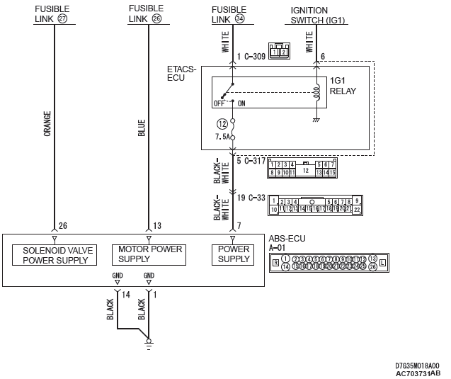
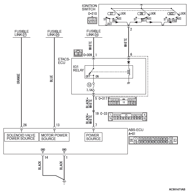
The ABS-ECU is energized by the valve power supply circuit (terminal No.26). When the power is supplied from the ignition switch (IG1) to the IG1 relay in ETACS-ECU, IG1 relay is turned on. At this time, the valve power supply circuit (terminal No.7) energizes the ABS-ECU.
DTC SET CONDITIONS
This DTC is set when the ABS-ECU power supply voltage drops below 9.7 +- 0.3 V during driving
PROBABLE CAUSES
- Battery failure
- Battery terminal loose
- Fusible link malfunction
- Damaged wiring harness and connectors
- ABS-ECU malfunction
- Charging system failed
DIAGNOSIS
Required Special Tools:
- MB991958: Scan Tool (M.U.T.-III Sub Assembly)
- MB991824: Vehicle Communication Interface (V.C.I.)
- MB991827: M.U.T.-III USB Cable
- MB991910: M.U.T.-III Main Harness A
- MB991974: ABS check harness
STEP 1. Using scan tool MB991958, diagnose the CAN bus line.
Use scan tool MB991958 to diagnose the CAN bus lines.
Q: Is the check result normal?
YES : Go to Step 3.
NO : Repair the CAN bus lines. (Refer to GROUP 54C − CAN Bus Diagnostics Table.) On completion, go to Step 2.
STEP 2. DTC recheck after resetting CAN bus lines
Q: Is DTC C2100 set?
YES : Go to Step 3.
NO : The procedure is complete.
STEP 3. Battery check
Q: Is the battery in good condition?
YES : Go to Step 5.
NO : Charge or replace the battery. Then go to Step 4.
STEP 4. Charging system check
Q: Is the charging system in good condition?
YES : Go to Step 5.
NO : Repair or replace the charging system component(s).
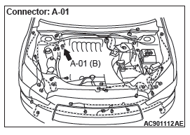
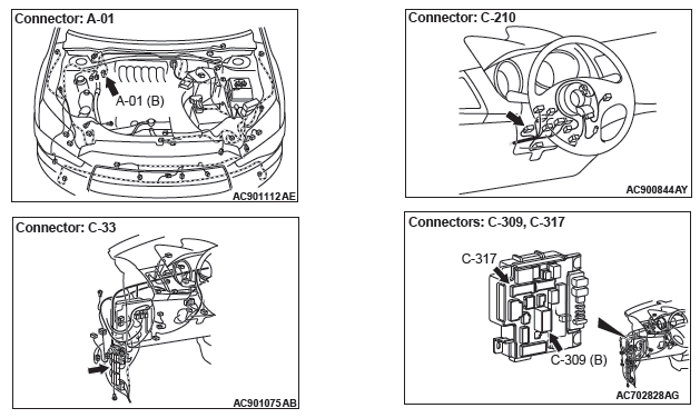
STEP 5. Connector check: A-01 ABS-ECU connector, C-33 intermediate connector, C-210 ignition switch connector, C-309 ETACS-ECU connector, C-317 ETACS-ECU connector
Q: Is the check result normal?
YES : Go to Step 6.
NO : Repair the damaged connector.
STEP 6. Fusible link check: Check the fusible link No.27.
Q: Is the check result normal?
YES : Go to Step 8.
NO : Go to Step 7.
STEP 7. Resistance measurement at A-01 ABS-ECU connector
- Removal the fusible link No.27.
- Disconnect the ABS-ECU connector, connect special tool
ABS check harness (MB991974) to the harness-side
connector, and then measure the resistance at the special
tool connector side.
NOTE: Do not connect the special tool ABS check harness (MB991974) to ABS-ECU.
- Measure the resistance between the terminal No.26 and the
body ground.
OK: No continuity
Q: Is the check result normal?
YES : Replace the fusible link No.27. Then go to Step 20.
NO : The short circuit may be present in the power supply circuit. Repair the wiring harness between the A-01 ABS-ECU connector terminal No.26 and the fusible link No.27, and then replace the fusible link No.27.
Then go to Step 20.
STEP 8. Voltage measurement at the A-01 ABS-ECU connector
- Disconnect the ASC-ECU connector, connect special tool
ABS check harness (MB991974) to the harness-side
connector, and then measure the voltage at the special tool
connector side.
NOTE: Do not connect the special tool ABS check harness (MB991974) to ASC-ECU.
- Measure the voltage between terminal No.26 and body
ground.
OK: Approximately system voltage
Q: Is the check result normal?
YES : Go to Step 9.
NO : The open circuit may be present in the power supply circuit. Repair the wiring harness between the A-01 ABS-ECU connector terminal No.26 and the fusible link No.27. Then go to Step 20.
STEP 9. Check the fuse No.12.
Visually check for open circuit in fuse No.12.
Q: Is the check result normal?
YES : Go to Step 11.
NO : Go to Step 10.
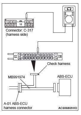
STEP 10. Resistance measurement at A-01 ABS-ECU connector
- Disconnect the C-317 ETACS-ECU connector.
- Disconnect the ABS-ECU connector, connect special tool
ABS check harness (MB991974) to the harness-side
connector, and then measure the resistance at the special
tool connector side.
NOTE: Do not connect the special tool ABS check harness (MB991974) to ABS-ECU.
- Measure the resistance between the terminal No.7 and the
body ground.
OK: No continuity
Q: Is the check result normal?
YES : Replace the fuse No.12. Then go to Step 20.
NO : The short circuit may be present in the power supply circuit. Repair the wiring harness between the A-01 ABS-ECU connector terminal No.7 and the C-317 ETACS-ECU connector terminal No.5, and then replace the fuse No.12. Then go to Step 20.
STEP 11. Measure the voltage at the C-309 ETACS-ECU connector.
- Disconnect the connector, and measure at the wiring harness-side connector.
- Measure the voltage between the terminal No.1 and the
body ground.
OK: Approximately system voltage
Q: Is the check result normal?
YES : Go to Step 14.
NO : Go to Step 12.
STEP 12. Fusible link check: Check the fusible link No.34.
Q: Is the check result normal?
YES : Go to Step 14.
NO : Go to Step 13.
STEP 13. Resistance measurement at C-309 ETACS-ECU connector
- Removal the fusible link No.34.
- Disconnect the C-309 ETACS-ECU connector, and then measure the resistance at the harness connector side.
- Measure the resistance between the terminal No.1 and the
body ground.
OK: No continuity
Q: Is the check result normal?
YES : Replace the fusible link No.34. Then go to Step 20.
NO : The short circuit may be present in the power supply circuit. Repair the wiring harness between the C-309 ETACS-ECU connector terminal No.1 and the fusible link No.34, and then replace the fusible link No.34.
Then go to Step 20.
STEP 14. Resistance measurement at fusible link No.34 and C-309 ETACS-ECU connector
- Disconnect the C-309 ETACS-ECU connector and fusible link No.34, and then measure the resistance at the harness connector side.
- Measure the resistance between the fusible link No.34 and
C-309 ETACS-ECU connector terminal No.1.
OK: Continuity exists (2 Ω or less)
Q: Is the check result normal?
YES : Go to Step 15.
NO : The open circuit may be present in the power supply circuit. Repair the wiring harness between the fusible link No.34 and C-309 ETACS-ECU connector terminal No.1. Then go to Step 20.
STEP 15. Resistance measurement at A-01 ABS-ECU connector
- Disconnect the C-317 ETACS-ECU connector.
- Disconnect the A-01 ABS-ECU connector, connect special
tool ABS check harness (MB991974) to the harness-side
connector, and then measure the resistance at the special
tool connector side.
NOTE: Do not connect the special tool ABS check harness (MB991974) to ABS-ECU.
- Measure the resistance between the A-01 ABS-ECU
connector terminal No.7 and the C-317 ETACS-ECU
connector terminal No.5.
OK: Continuity exists (2 Ω or less)
Q: Is the check result normal?
YES : Go to Step 16.
NO : The open circuit may be present in the power supply circuit. Repair the wiring harness between the A-01 ABS-ECU connector terminal No.7 and the C-317 ETACS-ECU connector terminal No.5. Then go to Step 20.
STEP 16. Measure the voltage at the C-317 ETACS-ECU connector.
- Measure by backprobing without disconnecting the connector.
- Turn the ignition switch to the ON position.
- Measure the voltage between the terminal No.6 and the
body ground.
OK: Approximately system voltage
Q: Is the check result normal?
YES : Go to Step 18.
NO : Go to Step 17.
STEP 17. Resistance measurement at C-317 ETACS-ECU connector and the C-210 ignition switch connector
- Disconnect the C-317 ETACS-ECU connector and C-210 ignition switch connector, and then measure the resistance at the harness connector side.
- Measure the resistance between the C-317 ETACS-ECU
connector terminal No.6 and C-210 ignition switch
connector terminal No.2.
OK: Continuity exists (2 Ω or less)
Q: Is the check result normal?
YES : Go to Step 18.
NO : The open circuit may be present in the power supply circuit. Repair the wiring harness between the C-317 ETACS-ECU connector terminal No.6 and C-210 ignition switch connector terminal No.2. Then go to Step 20.
STEP 18. Check whether the DTC is reset.
- Erase the DTC.
- Drive the vehicle at 12mph (20 km/h) or higher.
Q: Is the DTC C2100 set?
YES : Replace the ETACS-ECU (Refer to GROUP 54A − ETACS-ECU). Then go to Step 19.
NO : Intermittent malfunction (Refer to GROUP 00 − How to Use Troubleshooting/How to Cope with Intermittent Malfunctions).
STEP 19. Check whether the DTC is reset.
- Erase the DTC.
- Drive the vehicle at 12mph (20 km/h) or higher.
Q: Is the DTC C2100 set?
YES : Replace the hydraulic unit (integrated with ABS-ECU). Then go to Step 20.
NO : Intermittent malfunction (Refer to GROUP 00 − How to Use Troubleshooting/How to Cope with Intermittent Malfunctions).
STEP 20. Check whether the DTC is reset.
- Erase the DTC.
- Drive the vehicle at 12mph (20 km/h) or higher.
Q: Is the DTC C2100 set?
YES : Return to Step 1.
NO : The procedure is complete.
DTC C2101 Abnormality in battery voltage (high voltage)
CAUTION If there is any problem in the CAN bus lines, an incorrect DTC may be set. Prior to this diagnosis, diagnose the CAN bus lines (Refer to GROUP 54C − CAN Bus Line Diagnostic Flow).
OPERATION
The ABS-ECU is energized by the valve power supply circuit (terminal No.26). When the power is supplied from the ignition switch (IG1) to the IG1 relay in ETACS-ECU, IG1 relay is turned on. At this time, the valve power supply circuit (terminal No.7) energizes the ABS-ECU.
DTC SET CONDITIONS
This DTC is set when the ABS-ECU power supply voltage is more than 18.0 +- 1.0 V.
PROBABLE CAUSES
- Battery failure
- ABS-ECU malfunction
- Charging system failed
DIAGNOSIS
Required Special Tools:
- MB991958 Scan Tool (M.U.T.-III Sub Assembly)
- MB991824: Vehicle Communication Interface (V.C.I.)
- MB991827 M.U.T.-III USB Cable
- MB991910 M.U.T.-III Main Harness A
STEP 1. Using scan tool MB991958, diagnose the CAN bus line.
Use scan tool MB991958 to diagnose the CAN bus lines.
Q: Is the check result normal?
YES : Go to Step 3.
NO : Repair the CAN bus lines (Refer to GROUP 54C − CAN Bus Diagnostics Table). On completion, go to Step 2.
STEP 2. DTC recheck after resetting CAN bus lines
Q: Is DTC C2101 set?
YES : Go to Step 3.
NO : The procedure is complete.
STEP 3. Battery check
Q: Is the battery in good condition?
YES : Go to Step 5.
NO : Charge or replace the battery. Then go to Step 4.
STEP 4. Charging system check
Q: Is the charging system in good condition?
YES : Go to Step 5.
NO : Repair or replace the charging system component(s).
STEP 5. Check whether the DTC is reset.
- Erase the DTC.
- Drive the vehicle at 12mph (20 km/h) or higher.
Q: Is DTC C2101 set?
YES : Replace the hydraulic unit (integrated with ABS-ECU). Then go to Step 6.
NO : Intermittent malfunction (Refer to GROUP 00 − How to Use Troubleshooting/How to Cope with Intermittent Malfunction).
STEP 6. Check whether the DTC is reset.
- Erase the DTC.
- Drive the vehicle at 12mph (20 km/h) or higher.
Q: Is DTC C2101 set?
YES : Return to Step 1.
NO : The procedure is complete.
DTC C1395 Brake fluid filling not complete
CAUTION If there is any problem in the CAN bus lines, an incorrect DTC may be set. Prior to this diagnosis, diagnose the CAN bus lines (Refer to GROUP 54C − CAN Bus Line Diagnostic Flow).
DTC SET CONDITIONS
This DTC is set when the brake fluid is not filled in the hydraulic unit.
PROBABLE CAUSES
- Different hydraulic unit (For delivery to factory)
- ABS-ECU malfunction
DIAGNOSIS
Required Special Tools:
- MB991958: Scan Tool (M.U.T.-III Sub Assembly)
- MB991824: V.C.I.
- MB991827: M.U.T.-III USB Cable
- MB991910: M.U.T.-III Main Harness AThis DTC is set when the brake fluid is not filled in the hydraulic unit.
PROBABLE CAUSES
- Different hydraulic unit (For delivery to factory)
- ABS-ECU malfunction
DIAGNOSIS
Required Special Tools:
- MB991958: Scan Tool (M.U.T.-III Sub Assembly)
- MB991824: V.C.I.
- MB991827: M.U.T.-III USB Cable
- MB991910: M.U.T.-III Main Harness A
STEP 1. Using scan tool MB991958, diagnose the CAN bus line.
Use scan tool MB991958 to diagnose the CAN bus lines.
Q: Is the check result normal?
YES : Go to Step 2.
NO : Repair the CAN bus lines (Refer to GROUP 54C − CAN Bus Diagnostics Table). On completion, go to Step 2.
STEP 2. Check whether the DTC is reset.
Erase the DTC.
Q: Is the DTC C1395 set?
YES : Replace the hydraulic unit (integrated with ABS-ECU).
NO : This diagnosis is complete.
DTC C2203 VIN not recorded
CAUTION
- If there is any problem in the CAN bus lines, an incorrect DTC may be set. Prior to this diagnosis, diagnose the CAN bus lines (Refer to GROUP 54C − CAN Bus Line Diagnostic Flow).
- When other DTC for ABS-ECU is set, troubleshoot that DTC first.
OPERATION
ABS-ECU receives vehicle information from the engine control module and stores it.
DTC SET CONDITIONS
This DTC is set when ABS-ECU cannot receive the vehicle information from the engine control module.
PROBABLE CAUSES
- Malfunction of the CAN bus
- Engine control module malfunction
- ABS-ECU malfunction
- When the ignition switch is turned to the "ON" position for the first time after the ABS-ECU is replaced.
DIAGNOSIS
Required Special Tools:
- MB991958: Scan Tool (M.U.T.-III Sub Assembly)
- MB991824: Vehicle Communication Interface (V.C.I.)
- MB991827: M.U.T.-III USB Cable
- MB991910: M.U.T.-III Main Harness A
STEP 1. Using scan tool MB991958, diagnose the CAN bus line.
Use scan tool MB991958 to diagnose the CAN bus lines.
Q: Is the check result normal?
YES : Go to Step 3.
NO : Repair the CAN bus lines (Refer to GROUP 54C − CAN Bus Diagnostics Table). On completion, go to Step 2.
STEP 2. DTC recheck after resetting CAN bus lines
Q: Is the DTC C2203 set?
YES : Go to Step 3.
NO : The procedure is complete.
STEP 3. Scan tool DTC
Check that the engine control module sets a DTC.
Q: Is the DTC set?
YES (3.0L engine) : Troubleshoot the engine control module DTC (Refer to GROUP 13B − Diagnostic Trouble Code Chart). Then go to Step 5.
NO : Go to Step 4.
STEP 4. Check whether the DTC is reset.
- Erase the DTC.
- Ignition switch: "LOCK" (OFF) position
- Ignition switch: "ON" position
Q: Is the DTC C2203 set?
YES : Replace the hydraulic unit (integrated with ABS-ECU). Then go to Step 5.
NO : If a trouble is solved, it is determined that there is an intermittent malfunction such as poor engaged connector(s) or open circuit (Refer to GROUP 00 − How to Use Troubleshooting/How to Cope with Intermittent Malfunctions).
STEP 5. Check whether the DTC is reset.
- Erase the DTC.
- Ignition switch: "LOCK" (OFF) position
- Ignition switch: "ON" position
Q: Is the DTC C2203 set?
YES : Return to Step 1.
NO : The procedure is complete.
DTC C1608 Implausible diagnosis data
Power Supply Circuit
CAUTION
- If there is any problem in the CAN bus lines, an incorrect DTC may be set. Prior to this diagnosis, diagnose the CAN bus lines (Refer to GROUP 54C − CAN Bus Line Diagnostic Flow).
- If the ABS-ECU connector is disconnected or the battery terminal is disconnected when the ignition switch is ON, this DTC may be set.
- Since the failure information stored in the past is erased after this diagnosis is carried out, reproduce the state of malfunction.
OPERATION
The ABS-ECU stores DTCs and failure information in the EEPROM*.
The ABS-ECU is energized by the solenoid valve power supply circuit (terminal No.26).
NOTE: *:EEPROM (Electrical Erasable and Programmable ROM)
DTC SET CONDITIONS
- This DTC is set when the failure information stored in the EEPROM is not reliable. The failure information stored in the past is not output, and only this DTC is set.
- This DTC may occur when ABS-ECU power supply shutdown or drop between ABS-ECU is writing a data to the EEPROM.
PROBABLE CAUSES
- Disconnection of the ABS-ECU connector or the battery terminal when the ignition switch is ON
- Loose battery terminal
- Abnormality in battery
- Damaged wiring harness and connectors
- ABS-ECU malfunction
DIAGNOSIS
Required Special Tools:
- MB991958: Scan Tool (M.U.T.-III Sub Assembly)
- MB991824: Vehicle Communication Interface (V.C.I.)
- MB991827: M.U.T.-III USB Cable
- MB991910: M.U.T.-III Main Harness A
- MB991974: ABS check harness
STEP 1. Using scan tool MB991958, diagnose the CAN bus line.
Use scan tool MB991958 to diagnose the CAN bus lines.
Q: Is the check result normal?
YES : Go to Step 3.
NO : Repair the CAN bus lines (Refer to GROUP 54C − CAN Bus Diagnostics Table). On completion, go to Step 2.
STEP 2. DTC recheck after resetting CAN bus lines
Q: Is the DTC C1608 set?
YES : Go to Step 3.
NO : The procedure is complete.
STEP 3. Battery check
Q: Is the battery in good condition?
YES : Go to Step 5.
NO : Go to Step 4.
STEP 4. Charging system check
Q: Is the charging system in good condition?
YES : Replace the battery. Then go to Step 9.
NO : Repair or replace the charging system component(s).
STEP 5. Voltage measurement at the A-01 ABS-ECU connector
- Disconnect the ABS-ECU connector, connect special tool
ABS check harness (MB991974) to the harness-side
connector, and then measure the resistance at the special
tool connector side.
NOTE: Do not connect the special tool ABS check harness (MB991974) to ABS-ECU.
- Measure the voltage between the terminal No.26 and the
body ground.
OK: Approximately system voltage
Q: Is the check result normal?
YES : Go to Step 7.
NO : Go to Step 6.
STEP 6. Connector check: A-01 ABS-ECU connector
Q: Is the check result normal?
YES : The open or short circuit may be present in the power supply circuit. Repair the wiring harness between the A-01 ABS-ECU connector terminal No.26 and the fusible link No.27.
NO : Repair the defective connector.
STEP 7. Resistance measurement at A-01 ABS-ECU connector
- Disconnect the ABS-ECU connector, connect special tool
ABS check harness (MB991974) to the harness-side
connector, and then measure the resistance at the special
tool connector side.
NOTE: Do not connect the special tool ABS check harness (MB991974) to ABS-ECU.
- Measure the resistance between the terminal No.1 and the
body ground, and between the terminal No.14 and the body
ground.
OK: Continuity exists (2 Ω or less)
Q: Is the check result normal?
YES : Go to Step 9.
NO : Go to Step 8.
STEP 8. Connector check: A-01 ABS-ECU connector
Q: Is the check result normal?
YES : An open circuit may be present in the ground circuit.
Repair the wiring harness between the A-01 ABS-ECU connector terminal No.1 and the body ground, and between the A-01 ABS-ECU connector terminal No.14 and the body ground.
NO : Repair the defective connector.
STEP 9. Check whether the DTC is reset.
- Erase the DTC.
- Turn the ignition switch to the "LOCK" (OFF) position.
- Turn the ignition switch to the "ON" position.
- Drive the vehicle at 12 mph (20 km/h) or higher.
NOTE: The ABS warning light does not turn OFF in some cases unless the vehicle runs at 12 mph (20 km/h) or higher.
Q: Is any DTC set?
YES (DTC C1608 is set) : Replace the hydraulic unit (integrated with ABS-ECU).
YES (DTC other than C1608 is set) : Replace the hydraulic unit (integrated with ABS-ECU). Then go to step 10.
NO : Go to step 11.
STEP 10. Check whether the DTC is reset.
- Erase the DTC.
- Turn the ignition switch to the "LOCK" (OFF) position.
- Turn the ignition switch to the "ON" position.
- Drive the vehicle at 12 mph (20 km/h) or higher.
NOTE: The ABS warning light does not turn OFF in some cases unless the vehicle runs at 12 mph (20 km/h) or higher.
Q: Is DTC C1608 set?
YES : Return to Step 1.
NO : Go to step 11.
STEP 11. Check whether the DTC is reset.
- Erase the DTC.
- Turn the ignition switch to the "LOCK" (OFF) position.
- Turn the ignition switch to the "ON" position.
- Drive the vehicle at 12 mph (20 km/h) or higher.
NOTE: The ABS warning light does not turn OFF in some cases unless the vehicle runs at 12 mph (20 km/h) or higher.
Q: Is any DTC set?
YES : Carry out the applicable troubleshooting for the diagnostic trouble code.
NO : The procedure is complete.
DTC U0001 Bus off
CAUTION
- If there is any problem in the CAN bus lines, an incorrect DTC may be set. Prior to this diagnosis, diagnose the CAN bus lines (Refer to GROUP 54C − CAN Bus Line Diagnostic Flow).
- If DTC U0001 is set in ABS-ECU, always diagnose the CAN bus line. If there is any fault in the CAN bus lines, an incorrect DTC may be set. In this case, the set DTC is not highly reliable.
- Before replacing the ECU, ensure that the communication circuit is normal.
DTC SET CONDITIONS
This DTC is set when ABS-ECU has ceased the CAN communication (bus off).
COMMENTS ON TROUBLE SYMPTOM
Malfunction of wiring harness, connector (s), or ABS-ECU may be present.
PROBABLE CAUSES
- Wiring harness or connector failure of CAN bus line
- ABS-ECU malfunction
- Other ECU malfunction
DIAGNOSIS
Required Special Tools:
- MB991958: Scan Tool (M.U.T.-III Sub Assembly)
- MB991824: Vehicle Communication Interface (V.C.I.)
- MB991827: M.U.T.-III USB Cable
- MB991910: M.U.T.-III Main Harness A
STEP 1. Using scan tool MB991958, diagnose the CAN bus line.
Use scan tool MB991958 to diagnose the CAN bus lines.
Q: Is the check result normal?
YES : Go to Step 2.
NO : Repair the CAN bus lines (Refer to GROUP 54C − CAN Bus Diagnostics Table). On completion, go to Step 3.
STEP 2. Check whether the DTC is reset.
Erase the DTC.
Q: Is the DTC U0001 set?
YES : Replace the hydraulic unit (integrated with ABS-ECU).
NO : If the trouble symptom is resolved, an intermittent malfunction such as poorly engaged connector(s) or wiring harness is suspected (Refer to GROUP 00 − How to Use Troubleshooting/How to Cope with Intermittent Malfunctions).
STEP 3. Check whether the DTC is reset.
Erase the DTC.
Q: Is the DTC U0001 set?
YES : Return to Step 1.
NO : This diagnosis is complete.
DTC U0100 Engine time-out error
DTC U0141 ETACS time-out error
CAUTION
- If the DTCs U0100 and U0141 are set in ABS-ECU, always diagnose the CAN bus line. If there is any fault in the CAN bus lines (Refer to GROUP 54C − CAN Bus Line Diagnostic Flow), an incorrect DTC may be set. In this case, the set DTC is not highly reliable.
- Before replacing the ECU, ensure that the communication circuit is normal.
OPERATION
ABS-ECU communicates with the engine control module (ECM), AWD-ECU and ETACS-ECU via the CAN bus lines.
DTC SET CONDITIONS
This DTC is set if ABS-ECU cannot receive the signal sent from other ECU for a certain period.
PROBABLE CAUSES
DTC U0100
- Wiring harness or connector failure of CAN bus line
- Engine control module (ECM) malfunction
- ABS-ECU malfunction
- Connector disconnected or improperly connected
- Stretched or broken wires
DTC U0141
- Wiring harness or connector failure of CAN bus line
- Malfunction of ETACS-ECU
- ABS-ECU malfunction
- Connector disconnected or improperly connected
- Stretched or broken wires
DIAGNOSIS
Required Special Tools:
- MB991958: Scan Tool (M.U.T.-III Sub Assembly)
- MB991824: Vehicle Communication Interface (V.C.I.)
- MB991827: M.U.T.-III USB Cable
- MB991910: M.U.T.-III Main Harness A
STEP 1. Using scan tool MB991958, diagnose the CAN bus line.
Use scan tool MB991958 to diagnose the CAN bus lines.
Q: Is the check result normal?
YES : Go to Step 2.
NO : Repair the CAN bus lines (Refer to GROUP 54C − CAN Bus Diagnostics Table). On completion, go to Step 4.
STEP 2. Check whether the DTC is reset.
Q: Is DTC U0100 or U0141 set?
YES : Go to Step 3.
NO : The procedure is complete.
STEP 3. Scan tool other system DTC
Use scan tool MB991958 to check that other DTC is set in the ECU corresponding to the relevant diagnosis.
Q: Is other DTC set?
YES : Troubleshoot for the relevant DTC.
NO : Go to Step 4.
STEP 4. Connector check: ABS-ECU connector
Q: Is the check result normal?
YES : Go to Step 5.
NO : Repair the defective connector. Then go to Step 5.
STEP 5. ETACS-ECU coding data check
Check the following coding data stored in ETACS-ECU (Refer to GROUP 00 − Precautions before Service/Coding List).
Q: Is the check result normal?
YES : Go to Step 6.
NO : Replace the ETACS-ECU (Refer to GROUP 54A − ETACS-ECU). Then go to Step 6.
STEP 6. Check whether the DTC is reset.
Erase the DTCs.
Q: Is DTC U0100 or U0141 set?
YES : Replace the hydraulic unit (integrated with ABS-ECU).
NO : The procedure is complete.
DTC U1415 Variant coding not completed
CAUTION
- If there is any problem in the CAN bus lines, an incorrect diagnostic trouble code may be set. Prior to this diagnosis, diagnose the CAN bus lines (Refer to GROUP 54C − CAN Bus Line Diagnostic Flow).
- When the DTC U1415 is set in ABS-ECU, the DTC may also be set in ETACS-ECU. When the DTC is set in ETACS-ECU, carry out the diagnosis of the DTC for ETACS-ECU first.
OPERATION
- ABS-ECU receives the vehicle information stored in the ETACS-ECU via CAN bus lines.
- The ABS-ECU stores the tire size information sent from the ETACS.
DTC SET CONDITIONS
This DTC is set when the tire size information is not coded to the ABS-ECU.
PROBABLE CAUSES
- Variant coding for ETACS-ECU has not been implemented.
- Malfunction of ABS-ECU.
DIAGNOSIS
Required Special Tools:
- MB991958: Scan Tool (M.U.T.-III Sub Assembly)
- MB991824: Vehicle Communication Interface (V.C.I.)
- MB991827: M.U.T.-III USB Cable
- MB991910: M.U.T.-III Main Harness A
STEP 1. Using scan tool MB991958, diagnose the CAN bus line.
Use scan tool MB991958 to diagnose the CAN bus lines.
Q: Is the check result normal?
YES : Go to Step 2.
NO : Repair the CAN bus lines (Refer to GROUP 54C − CAN Bus Diagnostics Table). On completion, go to Step 4.
STEP 2. Scan tool other system DTC
Use scan tool MB991958 to check that the DTC B222C is set in the ETACS-ECU.
Q: Is any DTC set?
YES : Troubleshoot the relevant DTC, and then go to Step 4.
NO : Go to Step 3.
STEP 3. Check whether the DTC is reset.
- Erase the DTC.
- Turn the ignition switch to the "ON" position.
- Turn the ignition switch to the "OFF" position.
READ NEXT:
SYMPTOM CHART CAUTION ABS may operate in the following conditions without hard braking: Slippery road surface, high-speed turn, and bumpy road surface. When asking the customers, confirm that t Symptom Chart, Symptom Procedures
WHEEL SPEED SENSOR OUTPUT CURRENT MEASUREMENT Required Special Tools: MB991709: Wiring harness set The relevant wheel, on which the wheel speed sensor is fitted, should be free to run. 1. Remove t On-vehicle Service
REMOVAL AND INSTALLATION CAUTION The vehicle speed detection encoder collects any metallic particle easily, because it is magnetized. Make sure that the encoder should not collect any metallic partic Wheel Speed Sensor
SEE MORE:
KOS-ECU REMOVAL AND INSTALLATION CAUTION If KOS-ECU is replaced, refer to ID code registration need judgment table P.42B to complete the registration of each ID code. Removal KOS-ECU Exterior Transmitter Antenna Assembly, Interior Transmitter Antenna Assembly, Receiver Antenna Module REMOVAL AN KOS-ECU, Keyless Operation Key, TPMS Transmitter
Inspection Procedure 10: The lock switch of the liftgate lock release handle does not perform the locking operation. CAUTION Before replacing the ECU, ensure that the power supply circuit, the ground circuit and the communication circuit are normal. Liftgate Lock Release Handle Circuit PROBABLE Inspection Procedure 10-18
