Mitsubishi Outlander: Camshaft
REMOVAL AND INSTALLATION
Pre-removal Operation
- Engine Room Under Cover Front A, B and Engine Room Side Cover (RH) Removal.
- Air Cleaner Assembly Removal.
- Strut Tower Bar Removal.
Post-installation Operation
- Strut Tower Bar Installation.
- Air Cleaner Assembly Installation.
- Engine Room Under Cover Front A, B and Engine Room Side Cover (RH) Installation.
Camshaft removal steps
- Engine upper cover
- Ignition coil
- Breather hose connection
- PCV hose connection
- Control wiring harness connection
- Rocker cover assembly
- Rocker cover gasket
- Number 1 cylinder compression top dead center setting (only at removal.)
- Valve clearance adjustment (only at installation.)
- Service hole bolt
- Camshaft and camshaft sprocket assembly (exhaust side) removal preparatory operation (only at removal.)
- Front camshaft bearing cap
- Camshaft bearing
- Oil feed camshaft bearing cap (exhaust side)
- Camshaft bearing cap (exhaust side)
- Camshaft bearing cap (exhaust side)
- Thrust camshaft bearing cap (exhaust side)
- Camshaft and camshaft sprocket assembly (exhaust side)
- Camshaft sprocket (exhaust side)
- Camshaft (exhaust side)
- Camshaft bearing
- Oil feed camshaft bearing cap (intake side)
- Camshaft bearing cap (intake side)
- Camshaft bearing cap (intake side)
- Thrust camshaft bearing cap (intake side)
- Camshaft and camshaft sprocket assembly (intake side)
- Camshaft sprocket (intake side)
- Camshaft (intake side)
Oil feed control valve removal steps
- Engine upper cover
- Drive belt
- Power steering oil pump assembly
- Intake oil feeder control valve
- O-ring
- Exhaust oil feeder control valve
- O-ring
Required Special Tool:
- MB992103: Chain Tension Release Bar
REMOVAL SERVICE POINTS
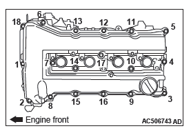
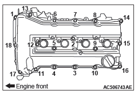
ROCKER COVER ASSEMBLY REMOVAL
Loosen the rocker cover assembly mounting bolts in the order of number shown in the figure, and remove the rocker cover assembly.
CYLINDER NO. 1 COMPRESSION TOP DEAD CENTER SETTING
CAUTION
Never turn the crankshaft counterclockwise.
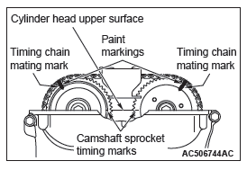
1. Turn the crankshaft clockwise so that the camshaft sprocket timing marks become horizontal to the cylinder head upper surface, and set the cylinder No. 1 to the top dead center of compression. At this time, check that the crankshaft pulley timing mark is in the 0-degree position of the ignition timing indicator of the timing chain case assembly.
2. Put paint marks on both the camshaft sprocket and timing chain at the position of camshaft sprocket timing chain mating mark (circular hole).
CAMSHAFT AND CAMSHAFT SPROCKET ASSEMBLY (EXHAUST SIDE) REMOVAL PREPARATORY OPERATION
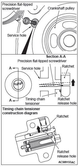
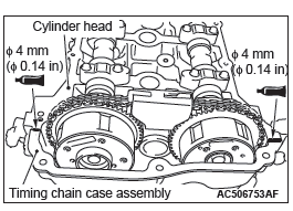
1. Insert a precision flat-tipped screwdriver through the service hole of the timing chain case, press up the timing chain tensioner ratchet to unlock, and keep the timing chain tensioner with that state.
NOTE: Lightly press down the tail end of the precision flat-tipped screwdriver to press up the tip of the precision flat-tipped screwdriver inserted to the timing chain tensioner to unlock.
CAUTION
- When inserting special tool MB992103 into the timing chain case assembly inside, pay attention to the position of the timing chain to avoid damage to the timing chain and timing chain tension side guide. Do not insert the special tool beyond its insertion guideline.
- If unlocking the timing chain tensioner is insufficient, the special tool cannot be inserted to the insertion guideline. Do not insert the special tool forcibly, follow Step 1 again to unlock the timing chain tensioner and insert the special tool.
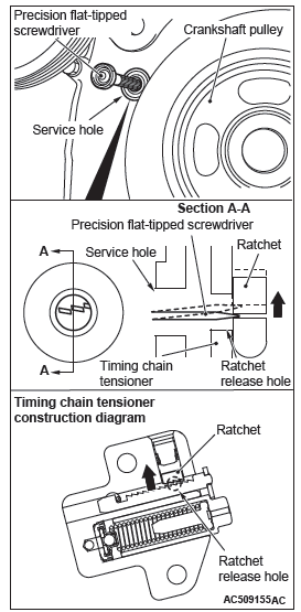
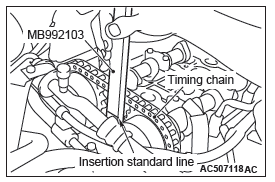
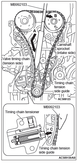
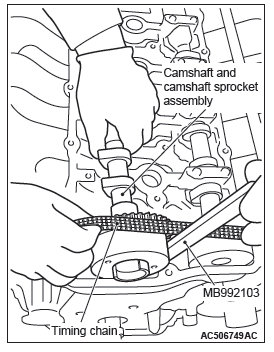
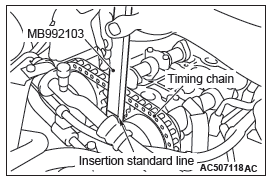
2. With the timing chain tensioner unlocked, insert special tool MB992103 inside the timing chain case assembly along the tension side of the timing chain until the insertion guide line aligns with the upper surface of the timing chain case assembly (Figure A).
NOTE: With the timing chain tensioner unlocked, insert the special tool along the tension side of the timing chain, according to the special tool top shape. The special tool can be inserted smoothly to the position where the special tool insertion guide line aligns with the timing chain case assembly top surface (Figure B), and the spread timing chain tension side guide can be held (Figure C).
3. With the special tool inserted up to the insertion guide line, press the special tool against the intake side camshaft sprocket and spread and hold the timing chain tension side guide.
4. Remove the flat-tipped precision screwdriver unlocking the timing chain tensioner.
CAUTION
The timing chain may snag on by other parts. After sagging the timing chain, never rotate the crankshaft.
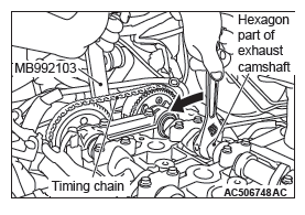
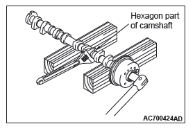
5. With the timing chain tension side guide spread, hook the special tool over the hexagon part of the camshaft on the exhaust side, and turn the camshaft clockwise to apply slack to the timing chain between the camshaft sprockets.
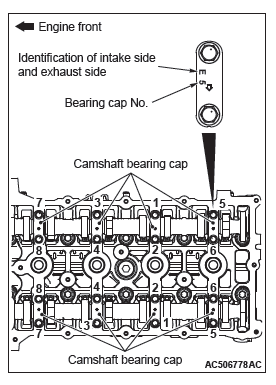
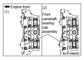
FRONT CAMSHAFT BEARING CAP ASSEMBLY REMOVAL
CAUTION
Be careful not to drop the camshaft bearing.
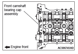
Loosen the mounting bolts of front camshaft bearing cap in the order of number shown in the figure, and remove the front camshaft bearing cap assembly.
CAMSHAFT BEARING OIL FEEDING CAP/CAMSHAFT BEARING CAP/CAMSHAFT BEARING THRUST CAP REMOVAL
CAUTION
When the camshaft bearing cap mounting bolts are loosened at once, the mounting bolts jump out by the spring force and the threads are damaged. Always loosen the mounting bolts in four or five steps.
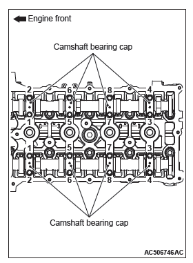
Loosen the mounting bolts of the camshaft bearing caps in the order of number shown in the figure in four or five steps, and remove the camshaft bearing caps.
CAMSHAFT AND CAMSHAFT SPROCKET ASSEMBLY (EXHAUST SIDE) REMOVAL
1. Raise slightly the transaxle side of the camshaft and camshaft sprocket assembly (exhaust side) by using the slack of the timing chain, and remove from the cam bearing.
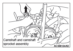
2. Remove the timing chain from the camshaft and camshaft sprocket assembly (exhaust side) toward the timing chain case assembly, and remove the camshaft and camshaft sprocket assembly (exhaust side) toward the transaxle.
3. Remove special tool MB992103 inserted into the timing chain case assembly.
CAUTION
The timing chain may snag on other parts. After removing the camshaft and camshaft sprocket assembly, never rotate the crankshaft.
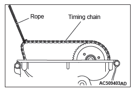
4. After removing the camshaft and camshaft sprocket assembly (exhaust side), hang up the timing chain with a rope to prevent the timing chain from falling into the timing chain case assembly.
CAMSHAFT SPROCKET/CAMSHAFT
REMOVAL
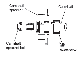
Hold the flats of the camshaft with a monkey wrench. Loosen the camshaft sprocket mounting bolts and remove the camshaft sprocket from the camshaft.
POWER STEERING OIL PUMP ASSEMBLY REMOVAL
1. With the hose installed, remove the power steering oil pump assembly from the bracket.
2. Tie the removed power steering oil pump assembly with a string at a position where it will not interfere with the removal and installation of oil control valve.
OIL FEEDER CONTROL VALVE REMOVAL
CAUTION
After removal of the oil feeder control valve, be careful to prevent dust from getting into the oil passage in the cylinder head.
INSTALLATION SERVICE POINTS
O-RING/OIL FEEDER CONTROL VALVE INSTALLATION
CAUTION
When installing the oil feeder control valve, be careful to avoid damage to the O-ring.
Apply engine oil to the O-ring of the oil feeder control valve and install the oil feeder control valve to the cylinder head.
CAMSHAFT/CAMSHAFT SPROCKET INSTALLATION
1. Use a monkey wrench to secure the flats of the camshaft in the same manner as removal.
2. Apply an adequate and minimum amount of engine oil to the camshaft and camshaft sprocket as shown in the figure.
3. Install the camshaft sprocket to the camshaft.
4. Apply an adequate and minimum amount of engine oil to the camshaft sprocket bolt.
5. Tighten the camshaft sprocket bolt to the specified torque.
Tightening torque: 59 +- 5 N*m (44 +- 3 ft-lb)
CAMSHAFT AND CAMSHAFT SPROCKET ASSEMBLY (INTAKE SIDE) INSTALLATION
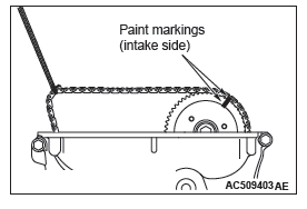
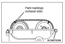
1. Align the intake side paint mark of the timing chain which was put at removal with the paint mark of the intake side camshaft sprocket, and install the camshaft sprocket to the timing chain.
2. Install the camshaft and camshaft sprocket assembly (intake side) to the cylinder head.
CAMSHAFT BEARING THRUST CAP/CAMSHAFT BEARING CAP/CAMSHAFT BEARING OIL FEEDING CAP/CAMSHAFT BEARING INSTALLATION
1. Install the camshaft bearing caps to the cylinder head.
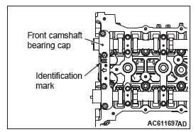
NOTE: Because the camshaft bearing thrust cap and camshaft bearing cap are the same in shape, check the bearing cap number and additionally its symbol to identify the intake and exhaust sides for correct installation.
2. Tighten each camshaft bearing cap mounting bolt to the specified torque in the order of number shown in the figure in two or three steps.
Tightening torque: 12 +- 1 N*m (107 +- 8 in-lb)
CAMSHAFT BEARING/CAMSHAFT AND CAMSHAFT SPROCKET ASSEMBLY (EXHAUST SIDE) INSTALLATION
CAUTION
- Be careful not to drop the camshaft bearing.
- When installing the camshaft and camshaft sprocket assembly (exhaust side), be careful not to let the camshaft bearing which is installed to the front cam bearing deviate from its position.
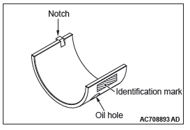
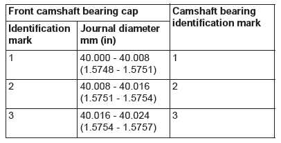
1. When replacing the camshaft bearing, according to the identification mark of front camshaft bearing cap in the table below, select a camshaft bearing with the corresponding size. Note that the identification mark of camshaft bearing is stamped on the place shown in the figure.
2. In the same manner as removal, insert the precision flat-tipped screwdriver through the service hole of the timing chain case, press up the ratchet of timing chain tensioner to unlock, and hold the unlocked timing chain tensioner.
NOTE: Lightly press down the tail end of the precision flat-tipped screwdriver to press up the tip of the precision flat-tipped screwdriver inserted to the timing chain tensioner to unlock.
CAUTION
- When inserting special tool MB992103 into the timing chain case assembly, pay attention to the position of the timing chain to avoid damage to the timing chain and timing chain tension side guide. Do not insert the special tool beyond its insertion guideline.
- If unlocking the timing chain tensioner is insufficient, the special tool cannot be inserted to the insertion guideline. Do not insert the special tool forcibly, follow Step 2 again to unlock the timing chain tensioner and insert the special tool.
3. With the timing chain tensioner unlocked, insert special tool MB992103 inside the timing chain case assembly along the tension side of the timing chain until the insertion guide line aligns with the upper surface of the timing chain case assembly (Figure A).
NOTE: With the timing chain tensioner unlocked, insert the special tool along the tension side of the timing chain, according to the special tool top shape. The special tool can be inserted smoothly to the position where the special tool insertion guideline aligns with the timing chain case assembly top surface, and the spread timing chain tension side guide can be hold.
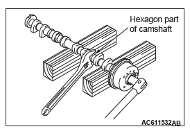
4. With the special tool inserted up to the insertion guide line, press the special tool against the intake side camshaft sprocket (Figure B) and spread and hold the timing chain tension side guide (Figure C).
5. Remove the flat-tipped precision screwdriver unlocking the timing chain tensioner.
6. Pull up the camshaft and camshaft sprocket assembly (exhaust side) mounting area of the timing chain (Figure D) to provide allowance for easy installation of the camshaft and camshaft sprocket assembly (exhaust side) to the timing chain.
CAUTION When installing the camshaft and camshaft sprocket assembly (exhaust side), be careful not to let the camshaft bearing which is installed to the front cam bearing deviate from its position.
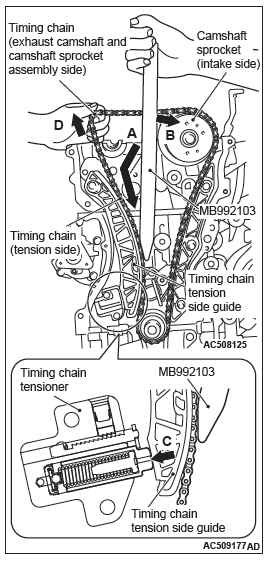
7. Align the exhaust side paint mark of the timing chain which was put at removal with the paint mark of the exhaust side camshaft sprocket, and install the timing chain to the camshaft sprocket.
8. Install the camshaft and camshaft sprocket assembly (exhaust side) to the cylinder head.
9. Remove the special tool inserted into the timing chain case assembly inside.
FRONT CAMSHAFT BEARING CAP ASSEMBLY INSTALLATION
CAUTION
When the mounting bolts are tightened with the front camshaft bearing cap tilted, the front camshaft bearing cap is damaged. Install the front camshaft bearing cap properly to the cylinder head and camshaft.
1. Install the front camshaft bearing cap to the cylinder head, and temporarily tighten the camshaft bearing front cap to the specified torque in the order of the figure (1).
Tightening torque: 17 +- 3 N*m (13 +- 2 ft-lb)
2. Tighten the front camshaft bearing cap again to the specified torque in the order of the figure (2).
Tightening torque: 30 +- 2 N*m (22 +- 1 ft-lb)
3. After the front camshaft bearing cap installation, check that the paint markings of the camshaft sprocket and the timing chain and the timing mark of the crankshaft pulley and the "T" mark position of ignition timing indicator are aligned respectively.
ROCKER COVER ASSEMBLY INSTALLATION
1. Wipe off the sealant on the mating surface of the rocker cover assembly and cylinder head and timing chain case assembly, and degrease the surface where the sealant is applied.
CAUTION
After the installation, until a sufficient period of time (one hour or more) elapses, do not apply the oil or water to the sealant application area or start the engine.
2. Apply sealant to the joint between the cylinder head and timing chain case assembly as shown in the figure and install the rocker cover assembly to the cylinder head.
Specified sealant: ThreeBond 1227D or equivalent
NOTE: Install the rocker cover assembly immediately after applying sealant.
3. Tighten the rocker cover assembly mounting bolts to the specified torque in the order of number shown in the figure.
Tightening torque: 3.0 +- 1.0 N*m (27 +- 8 in-lb)
4. Tighten again the rocker cover assembly mounting bolts to the specified torque in the order of number shown in the figure.
Tightening torque: 5.5 +- 0.5 N*m (49 +- 4 in-lb)
READ NEXT:
 Valve Stem Seal
REMOVAL AND INSTALLATION
CAUTION
*Remove and assemble the marked parts in each cylinder unit.
Pre-removal operation
Engine Room Under Cover Front B and Engine Room Side
Cover (RH) Removal
Engine
Oil Pan
REMOVAL AND INSTALLATION
Pre-removal operation
Engine Room Under Cover Front B and Engine Room
Side Cover (RH) Removal
Engine Oil Draining
Drive Belt Removal
Post-installation operation
Dri
Crankshaft Oil Seal
REMOVAL AND INSTALLATION
Crankshaft front oil seal removal
steps
Crankshaft pulley
Crankshaft front oil seal
Crankshaft rear oil seal removal
steps
Transaxle assembly
Drive plate bolts
Ad
SEE MORE:
DTC B1731, B1761, B1A08, B1A09, B1A0A, B1A0B, B1A10, B1A11, B1A12, B1A13,
B1A24, B1A25, B1A28, B1A35, B2101, B2102, B2204, B2206
DTC B1731: Engine Control Module communication timeout
CAUTION
When the DTC B1731 is set, be sure to diagnose
the CAN bus line.
When replacing the ECU, always check that
the communication circuit is normal.
DTC SET CONDITION
KOS-ECU checks that the Engine Control Module
data has been received
General Information
CENTRAL DOOR LOCKING SYSTEM
The central door locking system operates the door
lock actuator to lock or unlock the doors and liftgate
using the door lock switch built into the front power
window (main or sub RH) switch. The system has the
following operations and features:
All doors and liftgate ca
