Mitsubishi Outlander: Cylinder Head and Valves
REMOVAL AND INSTALLATION
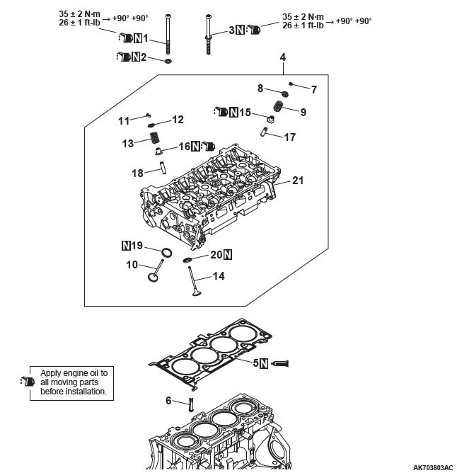
Removal steps
- Cylinder head bolt
- Cylinder head bolt washer
- Cylinder head bolt & washer assembly
- Cylinder head assembly
- Cylinder head gasket
- Engine oil control valve (OCV) filter
- Retainer lock
- Valve spring retainer
- Valve spring
- Intake valve
- Retainer lock
- Valve spring retainer
- Valve spring
- Exhaust valve
- Valve stem seal
- Valve stem seal
- Intake valve guide
- Exhaust valve guide
- Intake valve seat
- Exhaust valve seat
- Cylinder head
Required Special Tool:
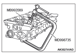
- MD998735: Valve spring compressor
- MB992089: Retainer holder
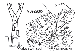
- MB992085: Valve stem seal pliers
REMOVAL SERVICE POINTS
RETAINER LOCK REMOVAL
CAUTION
Be careful not to allow retainer holder C to interfere with the wall of the tappet hole and to damage it.
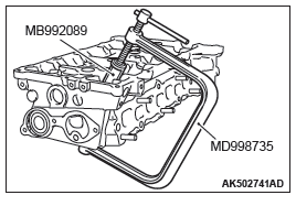
Use a special tool MD998735, and MB992089 to compress the valve spring and to remove the retainer lock.
NOTE: Store removed parts such as valves and springs with tags describing cylinder Number and installed position attached for reassembly.
VALVE STEM SEAL REMOVAL
Use special tool MB992085 to firmly pinch the base (larger external shape) of the stem seal and twist it right and left for pulling out.
INSTALLATION SERVICE POINTS
VALVE STEM SEAL INSTALLATION
CAUTION
- The valve stem seal must not be reused.
- Do not damage the tappet wall during assembly.
- Be sure to use a special tool to install the valve stem seal. Poor installation causes oil loss via valve guides.
- If oil is not applied, the valve stem seal may rise to the surface after it is press fitted.
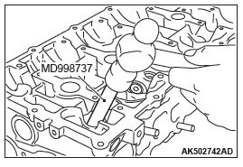
1. Apply a thin coat of engine oil to a new valve stem seal.
2. Use special tool MD998737 to press fit the valve stem seal into the valve guide with the valve stem used as a guide.
RETAINER LOCK INSTALLATION
Use a special tool MD998735, and MB992089 to compress the valve spring and to install the retainer lock.
CYLINDER HEAD GASKET / CYLINDER HEAD ASSEMBLY INSTALLATION
1. Completely remove the liquid gasket on the upper plane of the cylinder block and the lower plane of the cylinder head.
CAUTION
Sufficiently check that there is no residual oil on the place where degreasing is performed. If fingerprints are left, do not touch it with bare hands after the degreasing, since the oils from your fingers will harm the seal ability.
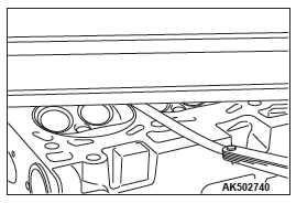
2. Degrease the place specified in the illustration.
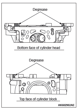
3. As shown in the illustration, apply a 2.5 +- 0.5 mm (0.1 +- 0.02 inch) of sealant to the top face of cylinder block.
Specified sealant: Three bond 1217G or exact equivalent
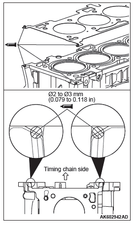
4. Install the cylinder head gasket.
NOTE: Check that the center of the liquid gasket is located toward the cylinder gasket in the position specified in the illustration.
5. As shown in the illustration, apply a 2.5 +- 0.5 mm (0.1 +- 0.02 inch) of sealant to the top face of cylinder head gasket.
Specified sealant: Three bond 1217G or exact equivalent
6. Install the cylinder head assembly.
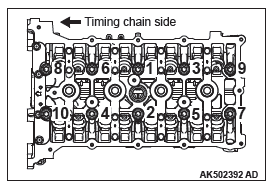
CYLINDER HEAD BOLT INSTALLATION
1. Install new cylinder head bolts and washers in the following procedure.
NOTE: Cylinder head bolts and washers must not be reused.
2. Apply an appropriate amount of engine oil to top and bottom surfaces of washers and threaded portion of bolts.
3. Install cylinder head bolts to the cylinder head.
NOTE: Bolts and washers are different parts for bolts on the timing chain side.
4. Tighten cylinder head bolts in several steps to the specified tightening torque of 35 +- 2 N*m (26 +- 1 ft-lb) according to the assembly order.
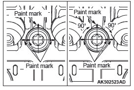
5. Put a paint mark on all of cylinder head bolt heads and cylinder head.
CAUTION
- When the tightening angle is smaller than the specified tightening angle, the appropriate tightening capacity cannot be secured.
- When the tightening angle is larger than the specified tightening angle, remove the bolt to start from the beginning again according to the procedure.
6. Tighten the cylinder head 90º according to the tightening order. Tighten it further 90º and make sure that the paint mark on the cylinder head bolt is in a straight line with that on the cylinder head.
INSPECTION
CYLINDER HEAD
1. Check the cylinder head for water leakage, gas leakage, damage or cracks before cleaning.
2. Completely remove oil, scale, sealant, carbon, etc. After cleaning oil passages, blow air to make sure that they are not clogged.
CAUTION
The grinding limit shall be within 0.2 mm (0.008 inch) in combination with the cylinder block to be assembled.
3. For the flatness on the cylinder head bottom, measure distortion using a straight edge and free gauge. If the distortion exceeds the limit, grind and repair it.
Distortion on bottom
Standard value: Within 0.05 mm (0.002 inch)
Limit: 0.2 mm (0.08 inch)
Grinding limit: 0.2 mm (0.008 inch)
Cylinder head height
Standard value: 128.5 mm (5.06 inch)
VALVE
1. Repair the valve seat if contact with the valve seat is poor, uneven or broken.
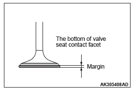
2. Measure the margin.
If the limit is exceeded, replace the valve.
Standard value:
Intake 1.022 mm (0.0402 inch)
Exhaust 1.094 mm (0.0431 inch)
Limit:
Intake 0.522 mm (0.0206 inch)
Exhaust 0.594 mm (0.0234 inch)
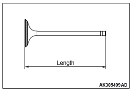
3. Measure overall length of the valve.
If the limit is exceeded, replace the valve.
Standard value:
Intake 113.18 mm (4.456 inch)
Exhaust 105.89 mm (4.169 inch)
Limit:
Intake 112.68 mm (4.436 inch)
Exhaust 105.39 mm (4.149 inch)
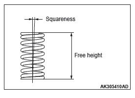
VALVE SPRING
1. Measure free height of the spring.
If the limit is exceeded, replace the spring.
Standard value: 47.20 mm (1.858 inch)
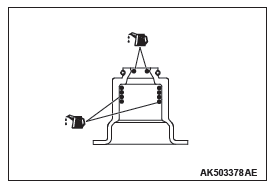
2. Measure squareness of the spring.
If the inclination exceeds the limit, replace the spring.
Standard value: 2º or less
Limit: 4º
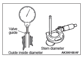
VALVE GUIDE
Measure clearance between the valve guide and valve stem. If the clearance exceeds the limit, replace the valve guide or valve, or both.
Standard value:
Intake 0.020 − 0.047 mm (0.0008 − 0.0019 inch)
Exhaust 0.030 − 0.054 mm (0.0012 − 0.0021 inch)
Limit:
Intake 0.10 mm (0.0039 inch)
Exhaust 0.11 mm (0.0043 inch)
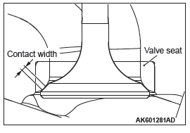
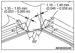
VALVE SEAT
Assemble the valve, then measure the contact width. If the measurement exceeds the specified limit, replace the valve seat.
Standard value
Intake: 1.16 − 1.46 mm (0.046 − 0.058 inch)
Exhaust: 1.35 − 1.65 mm (0.053 − 0.065 inch)
CAUTION
If the variation in the width exceeds 0.2 mm even if the contact width is within the standard value, replace or correct the valve sheet.
REPAIR PROCEDURE OF VALVE SEAT
1. Check clearance between valve guide and valve and replace the valve guide if necessary before repairing the valve seat.
2. Repair the valve seat so that seat width and seat angle are to the specified shape.
3. Lap valve and valve seat with lapping compound after repairing valve seat.
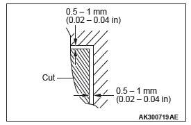
REPLACEMENT PROCEDURE OF VALVE SEAT
1. Scrape the valve seat to be replaced from inside to make its wall thickness thin before pulling out.
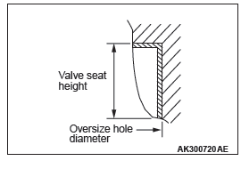
2. Repair the valve seat hole of the cylinder head to match it with the diameter of the oversize valve seat to be press fitted.
Intake valve seat bore diameter: 0.3 Over size: 36.22 − 36.24 mm (1.426 − 1.427 inch)
Exhaust valve seat bore diameter: 0.3 Over size: 30.22 − 30.24 mm (1.190 − 1.191 inch)
3. Press fit the valve seat, taking care not to score the cylinder head bore at room temperature.
4. Ream the valve seat.
Refer to "Repair procedure of valve seat".
REPLACEMENT PROCEDURE OF VALVE GUIDE
1. Pull out the valve guide with a press toward the cylinder block side.
2. Ream the valve guide hole of the cylinder head to match it with the diameter of the oversize valve guide to be press fitted.
CAUTION
Do not use a valve guide with the same size as that of the pulled out valve guide because it cannot be press fitted.
Valve guide bore diameter 0.25 Over size: 11.23 − 11.25 mm (0.442 − 0.443 inch)
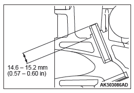
3. Press fit the valve guide to the illustrated dimension.
Standard value: 14.6 − 15.2 mm (0.57 − 0.60 inch)
NOTE: Press fit the valve guide from the cylinder head top surface.
4. After pressing fit the valve guide, insert a new valve to check for sliding.
READ NEXT:
 Balancer Chain
REMOVAL AND INSTALLATION
Removal steps
Drive plate bolt
Adapter plate
Drive plate
Rear oil seal
Balancer shaft chain tensioner
Balancer shaft tensioner lever
Balancer shaft chain guide
Balan
Piston and Connecting Rod
REMOVAL AND INSTALLATION
Removal steps
Connecting rod cap bolt
Connecting rod cap
Connecting rod bearing
Connecting rod bearing
Piston connecting rod assembly
Piston ring Number 1
Piston ring
Crankshaft and Cylinder Block
REMOVAL AND INSTALLATION
Removal steps
Crankshaft bearing cap bolt
Crankshaft bearing cap
Crankshaft bearing lower
Crankshaft
Crankshaft bearing upper
Thrust bearing
Crankshaft sensing ring
SEE MORE:
Symptom Procedures (Power Window)
INSPECTION PROCEDURE C-1: Power Windows do not Work at All.
CAUTION
Before replacing the ECU, ensure that the power supply circuit, the ground
circuit and the communication
circuit are normal.
Power Window Power Supply Circuit
CIRCUIT OPERATION
The ETACS-ECU turns on the power window relay to
ac
Balancer Shaft and Oil Pump Module
REMOVAL AND INSTALLATION
Pre-removal and Post-installation Operation
Engine Oil Pan Removal and Installation
Removal steps
Balancer shaft and oil pump
module
Required Special Tool:
MB991614: Angle Gauge
REMOVAL SERVICE POINT
BALANCER SHAFT AND OIL PUMP MODULE
REMOVAL
CAUTION
Never turn
