Mitsubishi Outlander: Piston and Connecting Rod
REMOVAL AND INSTALLATION
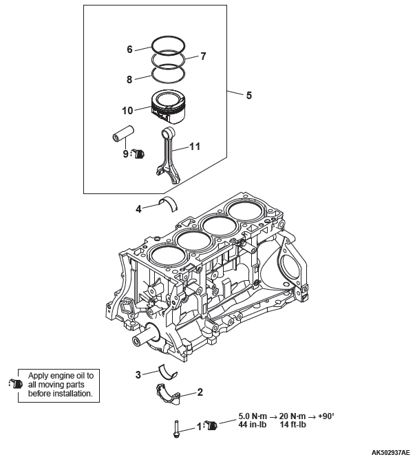
Removal steps
- Connecting rod cap bolt
- Connecting rod cap
- Connecting rod bearing
- Connecting rod bearing
- Piston connecting rod assembly
- Piston ring Number 1
- Piston ring Number 2
- Oil ring
- Piston pin
- Piston
- Connecting rod
Required Special Tool:
- MD998780: Piston pin setting tool
- MB991659: Guide D
- MD998718: Rear oil seal installer
REMOVAL SERVICE POINTS
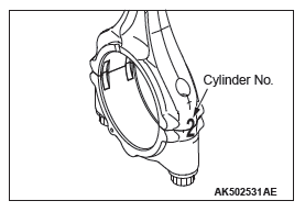
CONNECTING ROD REMOVAL
Enter cylinder Number for reassembly on the side of the connecting rod big end.
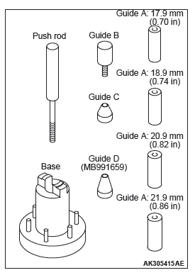
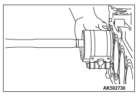
PISTON PIN REMOVAL
Special tool MD998780 consists of parts shown in the illustration.
Use also special tool MB991659 to remove the piston pin.
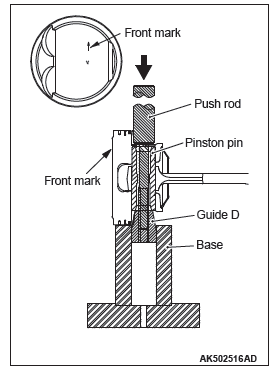
1. Insert the push rod into the piston pin from the front mark side of the piston top surface, and attach special tool MB991659.
2. Set the piston and connecting rod assembly on the base so that the front mark of the piston faces upward.
3. Use a press to push the push rod and pull out the piston pin.
NOTE: After pulling out the piston pin, organize pistons, piston pins and connecting rods by cylinder Number
INSTALLATION SERVICE POINTS
PISTON PIN INSTALLATION
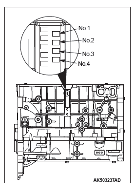
1. When replacing a piston, check the cylinder bore size mark stamped on the illustrated position of the cylinder block and select a corresponding piston from the table below.
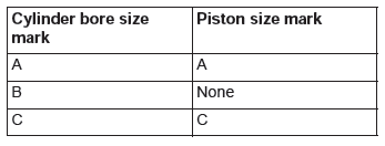
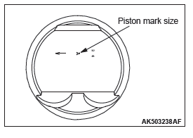
NOTE: The piston size mark is indicated on the piston top face.
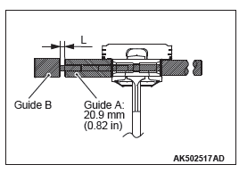
2. Insert the push rod into the piston pin and attach guide A.
3. Align the front mark of the piston with that of the connecting rod to assemble.
4. Apply engine oil to the circumference of the piston pin.
5. Insert the guide A side of the piston pin assembled in section 1 into the pin hole from the front mark side of the piston.
6. Screw guide B into guide A and open clearance between guide A and guide B by 3 mm (0.11 inch) (make the base in line with flushed surface) to assemble.
7. Set the piston on special tool piston setting base so that its front mark faces upward.
8. Use a press to press fit the piston pin. If the press fit load is below the standard value, replace the piston pin (piston assembly) or connecting rod, or both.
Standard value: 7,500 − 17,500 N (1.686 − 3.934 lbf)
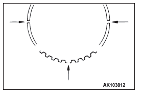
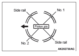
OIL RING INSTALLATION
1. Assemble the spacer of the oil ring into the piston ring groove. Then, assemble the upper side rail, and after this assemble the lower side rail.
NOTE: Install the side rail and end gap of the spacer so that they are at the position as shown in the illustration.
CAUTION
The side rail may be broken if its end gap is widened by a ring expander as in other piston rings.
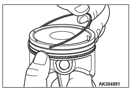
2. When assembling the side rail, push it by fingers, after fitting one end of the side rail into the piston groove, for easy assembly.
3. After assembling the oil ring into the piston, make sure that the side rail turns smoothly to either direction.
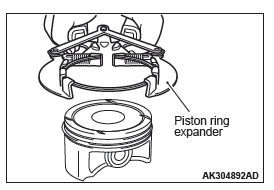
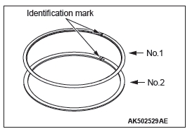
PISTON RING NUMBER. 2 / PISTON RING NUMBER. 1 INSTALLATION
Use a piston ring expander to assemble piston rings with their identification marks facing upward. Piston rings can be assembled by hand without using the piston ring expander.
Identification mark:
Number 1 ring: 1T
Number 2 ring: 2T
PISTON CONNECTING ROD ASSEMBLY INSTALLATION
1. Apply a sufficient amount of engine oil to the circumference of the piston, piston rings and oil ring.
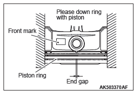
2. Arrange end gap positions of piston rings and oil ring (side rail and spacer) as shown in the illustration.
3. Insert the piston and connecting rod assembly from the top surface of the cylinder block with the front mark of the piston top face facing toward the timing belt side.
CAUTION
Driving it in hard causes breakage of piston rings and damage to the crank pin.
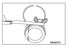
4. Firmly tighten the piston ring with a ring band and insert the piston and connecting rod assembly.
CONNECTING ROD BEARING INSTALLATION
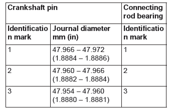
1. When replacing a connecting rod bearing, select the bearing corresponding to the crankshaft pin outside diameter according to the crankshaft pin identification in the table below.
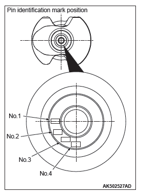
2. An identification mark of a crankshaft is stamped at the illustrated position by Number
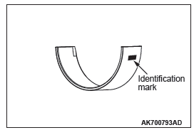
3. A connecting rod bearing has an identification mark at the illustrated position.
CONNECTING ROD CAP INSTALLATION
NOTE: The connecting rod resulting from the breaking process has the high insertion force. The new connecting rod assembly may possibly be difficult to remove the connecting rod.
If difficult to remove it, alternately strike the two bolt heads with a plastic hammer while the connecting rod bolt is slightly loosened, or strike the center of the cap shaft's inside diameter slightly and outward.
If the outside of the cap is directly struck, the lateral force is added to the broken-out section. Thus, pay attention to the broken- out section that might be difficult to be separated or might fall.
Clean the broken-out section before the installation to the engine, using compression air.
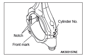
1. Assemble the bearing cap on the connecting rod by aligning it with the mark put during removal. If a new connecting rod without a mating mark is used, assemble so that the detent notch of the bearing is on the same side as illustrated.
2. Make sure that clearance of the thrust of the connecting rod big end is appropriate.
Standard value: 0.10 − 0.25 mm (0.004 − 0.010 inch)
Limit: 0.4 mm (0.016 inch)
CONNECTING ROD CAP BOLT INSTALLATION
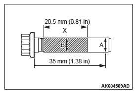
1. Check in the following procedure before reusing the connecting rod bolt.
- Measure the outside diameter "A".
- Measure the smallest outside diameter "B" within the range "X" shown in the illustration.
- If the difference of outside diameter of thread exceeds the limit, replace the connecting rod bolt.
Limit: 0.1 mm (0.004 inch)
2. Apply engine oil to the threaded portion and seat surface of the bolt before installing it.
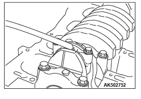
3. After installing each bolt and tightening it by fingers, tighten bolts alternately to properly assemble the cap.
4. Tighten the bolt in several steps until the torque reaches 5.0 N*m (44 in-lb).
5. Tighten the bolt in several steps until the torque reaches 20 N*m (14 ft-lb).
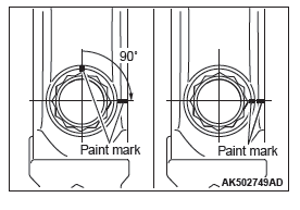
6. Put a paint mark on the bolt head as illustrated.
7. Put a paint mark on the connecting rod at 90º position in the tightening direction of the bolt with reference to the paint mark position of the bolt.
CAUTION
- When the tightening angle is smaller than the specified tightening angle, the appropriate tightening capacity cannot be secured.
- When the tightening angle is larger than the specified tightening angle, remove the bolt to start from the beginning again according to the procedure.
8. Tighten the bolt 90º, and make sure that the paint mark of the connecting rod is aligned with that of the bolt.
INSPECTION
PISTON RINGS
1. Check clearance between piston rings and ring grooves. If the limit is exceeded, replace piston rings or piston, or both.
Standard value:
Number 1 ring: 0.03 − 0.07 mm (0.001 − 0.003 inch)
Number 2 ring: 0.03 − 0.07 mm (0.001 − 0.003 inch)
Limit: 0.1 mm (0.004 inch)
2. Put piston rings into the cylinder bore, press them against the piston top face, and push them in. After achieving squareness, measure the end gap with a free gauge. If the end gap is excessive, replace piston rings.
Standard value:
Number 1 ring: 0.15 − 0.25 mm (0.006 − 0.011 inch)
Number 2 ring: 0.25 − 0.40 mm (0.010 − 0.016 inch)
Oil ring: 0.10 − 0.35 mm (0.004 − 0.014 inch)
Limit:
Number 1 ring: 0.8 mm (0.03 inch)
Number 2 ring: 0.8 mm (0.03 inch)
Oil ring: 1.0 mm (0.04 inch)
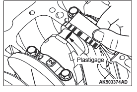
CRANKSHAFT PIN OIL CLEARANCE (PLASTIGAGE METHOD)
1. Wipe oil off the crankshaft pin and connecting rod bearing.
2. Place a plastigage in length equal to the bearing width on the pin shaft straight in alignment with the shaft center.
3. Carefully install the connecting rod cap and tighten bolts to the specified tightening torque of 5.0 N*m (44 in-lb) → 20 N*m (15 ft-lb) → +90º.
4. Remove bolts and gently remove the connecting rod cap.
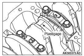
5. Measure the crushed plastigage width (area most widely crushed) using a scale printed on the plastigage bag.
Standard value: 0.018 − 0.045 mm (0.0007 − 0.0018
inch)
Limit: 0.1 mm (0.04 inch)
READ NEXT:
 Crankshaft and Cylinder Block
REMOVAL AND INSTALLATION
Removal steps
Crankshaft bearing cap bolt
Crankshaft bearing cap
Crankshaft bearing lower
Crankshaft
Crankshaft bearing upper
Thrust bearing
Crankshaft sensing ring
Engine Lubrication
General Information
The lubrication method is a fully force-fed, full-flow filtration
type.
ENGINE OILS
WARNING
Prolonged and repeated contact with mineral
oil will result in the removal of natural f
Engine Cooling
General Information
The cooling system is designed to keep every part of
the engine at appropriate temperature in whatever
condition the engine may be operated. The cooling
method is of the water-cool
SEE MORE:
Engine Cooling
General Information
The cooling system is designed to keep every part of
the engine at appropriate temperature in whatever
condition the engine may be operated. The cooling
method is of the water-cooled, pressure forced circulation
type in which the water pump pressurizes coolant
and circulates it t
DTC C2104, C1073, C2116, C1000, C2200, C2100, C2101, C1395, C2203,
C1608, U0001, U0100, U0141, U1415, U1417
DTC C2104 Faulty valve power supply circuit
Power Supply Circuit
CAUTION
If there is any problem in the CAN bus lines, an incorrect
DTC may be set. Prior to this diagnosis, diagnose the CAN
bus lines (Refer to GROUP 54C − CAN Bus Line Diagnostic
Flow).
OPERATION
ABS-ECU contains the power
