Mitsubishi Outlander: Balancer Chain
REMOVAL AND INSTALLATION
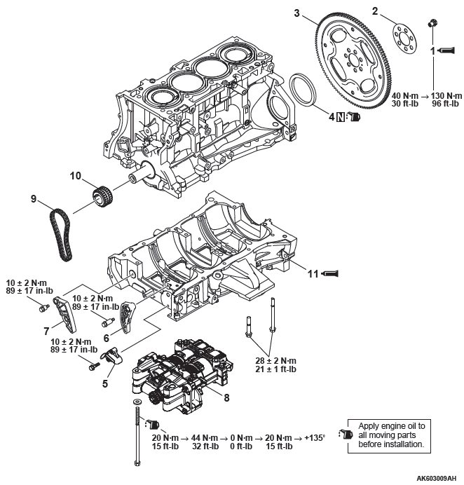
Removal steps
- Drive plate bolt
- Adapter plate
- Drive plate
- Rear oil seal
- Balancer shaft chain tensioner
- Balancer shaft tensioner lever
- Balancer shaft chain guide
- Balancer shaft module
- Balancer chain
- Crankshaft sprocket
- Ladder frame
Required Special Tool:
- MB991883: Flywheel stopper
- MB991614: Angle gauge
- MD998718: Rear oil seal installer
REMOVAL SERVICE POINTS
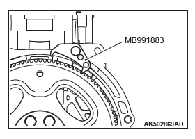
DRIVE PLATE BOLT REMOVAL
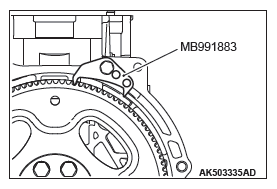
1. Use special tool MB991883 to secure the drive plate.
2. Remove the drive plate bolts.
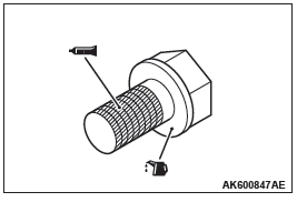
BALANCER SHAFT CHAIN TENSIONER / CRANKSHAFT SPROCKET / BALANCER CHAIN / BALANCER SHAFT MODULE REMOVAL
CAUTION
Reliably secure the plunger of the chain tensioner with hard wire to prevent it from jumping out of the main body.
1. Push in the balancer shaft tensioner lever by hand and push in the plunger of the chain tensioner until it contacts the bottom. Then, insert hard wire (piano wire, etc.) of φ1.5 or hexagonal bar wrench (1.5 mm [0.06 inch] ) into the plunger fixing hole to secure.
2. Remove the balancer shaft chain tensioner.
CAUTION
The balancer shaft module must not be disassembled because of assembly warranty.
3. Remove the crankshaft sprocket, balancer chain and balancer shaft module as a unit.
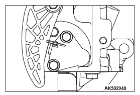
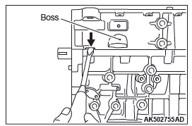
LADDER FRAME REMOVAL
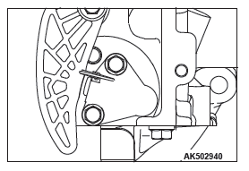
1. Pry the illustrated position with a screwdriver or tap the boss with a hammer.
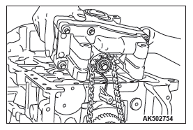
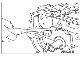
2. If the ladder frame does not come off, insert a flatblade screwdriver into the gap between the ladder frame and bearing cap as shown in the illustration and lightly pry it to remove the ladder frame.
INSTALLATION SERVICE POINTS
LADDER FRAME INSTALLATION
CAUTION
Be sure to remove liquid gasket that has entered mounting holes.
1. Completely remove liquid gasket adhering to the cylinder block and ladder frame.
CAUTION
Sufficiently check that there is no residual oil on the place where degreasing is performed. If fingerprints are left, do not touch it with bare hands after the degreasing, since the oils from your fingers will harm the seal ability.
2. Degrease the surface where the liquid gasket is applied and the contact surface between the cylinder block and ladder frame.
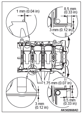
3. Squeeze liquid gasket of φ2.5 +- 0.5 mm (0.10 +- 0.02 inch) in thickness and apply it to the illustrated position of the ladder frame.
Specified sealant: Three bond 1217G or exact equivalent
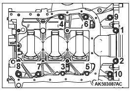
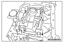
4. Tighten the ladder frame to the specified tightening torque in the order shown in the illustration.
Tightening torque: 28 +- 2 N*m (21 +- 1 ft-lb)
CRANKSHAFT SPROCKET / BALANCER CHAIN / BALANCER SHAFT MODULE INSTALLATION
When the new balancer shaft module is installed, supply oil to the oil pump and the balancer shaft bearing in the balancer shaft module using the following procedures.
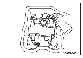
- Clean the inside of the removed oil pan. Put the balancer shaft module carefully into the oil pan so that the oil inlet can be upward.
- Pour the engine oil so that the two-third of the balancer module can be immersed.
- Also, pour approximate 50 cm3 (3.1 cu in) of engine oil from the oil inlet.
- By giving four clockwise rotations or more to the balancer shaft sprocket, the oil is supplied to the oil pump and the balancer shaft bearing.
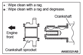
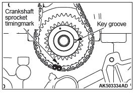
1. Wipe the dirt on the crankshaft sprocket and the crankshaft using a rag, and then remove the grease from the portion shown in the illustration.
NOTE: Remove grease to prevent a drop in the coefficient of friction of the pressing portion caused by adhesion of oil.
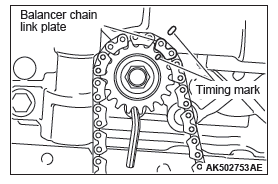
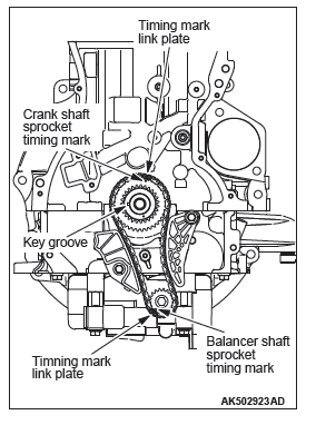
2. Align the timing mark of the balancer shaft module sprocket with that of the balancer shaft module.
3. Insert a hexagonal bar wrench (3 mm [0.12 inch] ) as illustrated to prevent the balancer shaft module sprocket from moving.
4. Loop the balancer chain, aligning its link plate with the timing mark.
5. Install the crankshaft sprocket on the crankshaft.
NOTE: Do not push in the crankshaft sprocket to the normal position. Push it in only up to the tip of the crankshaft.
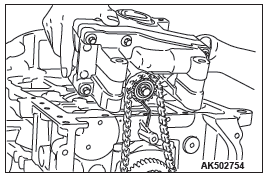
6. While slanting the balancer shaft module, align the link plate of another balancer chain with the timing mark of the crankshaft sprocket to loop. Gradually push in the crankshaft sprocket and fit it into the key groove of the crankshaft. Then, install the balancer shaft module on the ladder frame.
NOTE: Make sure that the balancer shaft module is completely intimate contact with the ladder frame.
NOTE: Make sure that the key groove of the crankshaft is aligned with the contact surface of the cylinder block and ladder frame as shown in the illustration.
7. Apply an appropriate and minimum amount of engine oil to the screw thread of the balancer shaft module bolt.
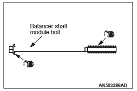
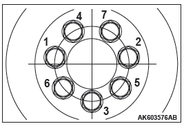
8. Tighten bolts to the specified tightening torque of 20 N*m (14 ft-lb) according to the assembly order in the illustration, retighten them to 44 N*m (32 ft-lb), and then completely loosen them.
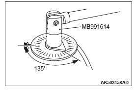
9. After tightening them to the specified tightening torque of 20 N*m again, use special tool MB991614 to tighten them up to 135º.
10.Pull out the hexagonal bar wrench from the balancer module sprocket.
11.Make sure that the respective timing mark is aligned with each other as illustrated.
12.Install the balancer chain tensioner lever and balancer chain guide.
BALANCER SHAFT CHAIN TENSIONER INSTALLATION
1. Attach the chain tensioner to the ladder frame.
CAUTION
Install the chain tensioner precisely in place after installing the tensioner lever and chain guide to prevent the plunger of the chain tensioner from jumping out.
2. Remove the hard wire (piano wire, etc.) of φ1.5 or hexagonal bar wrench (1.5 mm [0.06 inch] ) from the tensioner. This enables the plunger of the chain tensioner to push the balancer shaft tensioner lever to keep the balancer shaft chain tight.
REAR OIL SEAL INSTALLATION
CAUTION
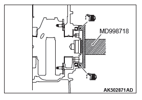
Do not apply oil to the circumference of the oil seal and oil seal pressing hole on the cylinder block side to prevent teeth from pulling out.
After applying a small amount of engine oil to the oil seal lip, use special tool MD998718 to press fit the oil seal.
DRIVE PLATE BOLT INSTALLATION
1. Clean off sealant and oil of thread of crankshaft and drive plate bolt.
2. Use special tool MB991883 to secure the drive plate.
3. Apply engine oil to thread of crankshaft and bolt seat area of drive plate.
4. Apply the sealant to the thread of drive plate bolt.
Specified sealant: Three bond 1324 or equivalent
5. Tighten drive plate bolts to temporary torque of 40 N*m (32 ft-lb) in the order shown to illustration.
6. Tighten drive plate bolts to specified tightening torque of 130 N*m(95 ft-lb) in the order shown in the illustration.
READ NEXT:
 Piston and Connecting Rod
REMOVAL AND INSTALLATION
Removal steps
Connecting rod cap bolt
Connecting rod cap
Connecting rod bearing
Connecting rod bearing
Piston connecting rod assembly
Piston ring Number 1
Piston ring
Crankshaft and Cylinder Block
REMOVAL AND INSTALLATION
Removal steps
Crankshaft bearing cap bolt
Crankshaft bearing cap
Crankshaft bearing lower
Crankshaft
Crankshaft bearing upper
Thrust bearing
Crankshaft sensing ring
Engine Lubrication
General Information
The lubrication method is a fully force-fed, full-flow filtration
type.
ENGINE OILS
WARNING
Prolonged and repeated contact with mineral
oil will result in the removal of natural f
SEE MORE:
Window Glass Runchannel and Door Opening Weatherstrip
REMOVAL AND INSTALLATION
<Front door>
Waterproof film removal steps
Pull handle bracket
Waterproof film
Door window glass runchannel
removal steps
Door window glass runchannel
Door belt line weatherstrip inner
removal steps
Door trim assembly
Door belt line weatherstrip inner
Battery
GENERAL INFORMATION
The 80D26L battery has been adopted for 3.0L
engine.
The 75D23L battery has been adopted for 2.4L
engine.
ON-VEHICLE SERVICE
BATTERY CHECK
WARNING
Battery posts, terminals and related accessories contain
lead and lead compounds. WASH HANDS AFTER
HANDLING.
BATTERY VISUAL I
