Mitsubishi Outlander: DTC B2352, B2400, B2401, B2402, B2403, B2404, B2405, B2406, B2407, B2408, B2409, B240A, B240B, B240C, B240D, B240E
DTC B2352: Antenna fail
CAUTION When replacing the ECU, always check that the communication circuit is normal.
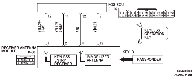
Receiver Antenna Module and KOS-ECU Circuit
DTC SET CONDITION
If an open circuit or short to ground occurs in the antenna, KOS-ECU sets the DTC B2352.
TECHNICAL DESCRIPTION (COMMENT)
When the ignition switch is turned ON with the emergency operation by the inversely-inserted keyless operation key, KOS-ECU sends signals to the receiver antenna module. The receiver antenna transmits random numbers to the keyless operation key when it receives signals from KOS-ECU. If an open circuit or short to ground occurs on the wiring harness between KOS-ECU and receiver antenna at this time, KOS-ECU determines that there is a problem.
TROUBLESHOOTING HINTS
- Malfunction of the receiver antenna module
- Damaged wiring harness and connectors
- Malfunction of KOS-ECU
DIAGNOSIS
Required Special Tools:
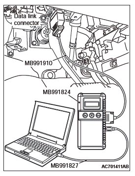
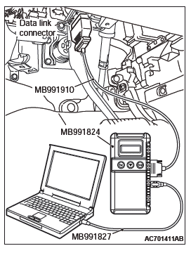
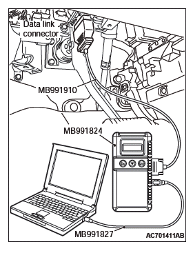
- MB991958: Scan Tool (M.U.T.-III Sub Assembly)
- MB991824: Vehicles Communication Interface (V.C.I.)
- MB991827: M.U.T.-III USB Cable
- MB991910: M.U.T.-III Main Harness A (Vehicles with CAN communication system)
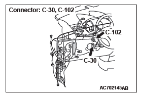
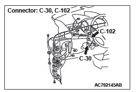
STEP 1. Check receiver antenna module connector C-30 and KOS-ECU connector C-102 for loose, corroded or damaged terminals, or terminals pushed back in the connector.
Q: Is the receiver antenna module connector C-30 and KOS-ECU connector C-102 in good condition?
YES : Go to Step 2.
NO : Repair the defective connector.
STEP 2. Check the wiring harness between the receiver antenna module connector C-30 (terminal No. 1, 2) and the KOS-ECU connector C-102 (terminal No. 12, 11).
- Check the signal lines for open circuit and short circuit.
Q: Is the wiring harness between receiver antenna module connector C-30 (terminal No. 1, 2) and the KOS-ECU connector C-102 (terminal No. 12, 11) in good condition?
YES : Go to Step 3.
NO : The wiring harness may be damaged or the connector(s) may have loose, corroded or damaged terminals, or terminals pushed back in the connector.
Repair the wiring harness as necessary.
STEP 3. Replace the receiver antenna module, and check whether the diagnostic trouble code is reset.
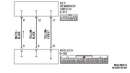
CAUTION To prevent damage to scan tool MB991958, always turn the ignition switch to the "LOCK" (OFF) position before connecting or disconnecting scan tool MB991958.
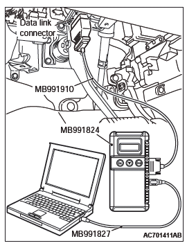
- Connect scan tool MB991958. Refer to "How to connect scan too (M.U.T.-III)".
- Erase the DTC.
- Turn the ignition switch from the "LOCK" (OFF) position to the "ON" position.
- Check if the DTC is set.
Q: Is the DTC set?
YES : Replace KOS-ECU and register the ID codes. NO : The procedure is complete.
DTC B2400: KOS key registration fail
CAUTION
- If the DTC B2400 is set, diagnose the CAN bus lines.
- When replacing the ECU, always check that the communication circuit is normal.
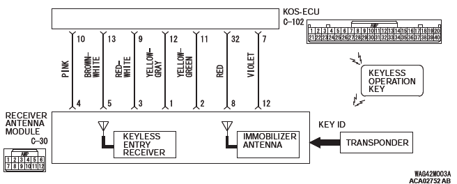
Receiver Antenna Module and KOS-ECU Circuit
DTC SET CONDITION
If the registration of the keyless operation key ID to KOS-ECU fails, KOS-ECU sets the DTC B2400.
TECHNICAL DESCRIPTION (COMMENT)
Assuming that another keyless operation key has already been registered with KOS-ECU, if the registration of the keyless operation key ID fails when a new keyless operation key is added or the existing key is replaced, KOS-ECU determines that there is a problem.
TROUBLESHOOTING HINTS
- Keyless operation key ID registration failure
- Malfunction of the keyless operation key
- Malfunction of CAN bus line
- Battery drain of keyless operation key
- Damaged wiring harness and connectors
- Malfunction of receiver antenna module
- Malfunction of KOS-ECU
DIAGNOSIS
Required Special Tools:
- MB991958: Scan Tool (M.U.T.-III Sub Assembly)
- MB991824: Vehicles Communication Interface (V.C.I.)
- MB991827: M.U.T.-III USB Cable
- MB991910: M.U.T.-III Main Harness A (Vehicles with CAN communication system)
STEP 1. Using scan tool MB991958, diagnose the CAN bus line.
CAUTION To prevent damage to scan tool (MB991958), always turn the ignition switch to the "LOCK" (OFF) position before connecting or disconnecting scan tool (MB991958).
- Connect scan tool MB991958 to the data link connector.
- Turn the ignition switch to the "ON" position.
- Diagnose the CAN bus line.
- Turn the ignition switch to the "LOCK" (OFF) position.
Q: Is the CAN bus line found to be normal?
YES : Go to Step 2.
NO : Repair the CAN bus line.
STEP 2. Replace the battery in the keyless operation key and recheck the diagnostic trouble code.
Replace the battery of the keyless operation key for which the DTC is set, and check whether the DTC is reset.
- Turn the ignition switch from the "LOCK" (OFF) position to the "ON" position.
- Check if the DTC is set.
Q: Is the DTC set?
YES : Go to Step 3.
NO : The procedure is complete. (Discharged battery)
STEP 3. Replace the keyless operation key and recheck the diagnostic trouble code.
Replace the keyless operation key for which the DTC is set with a new one, register the encrypted code and keyless operation key ID, and check whether the DTC is reset.
- Turn the ignition switch from the "LOCK" (OFF) position to the "ON" position.
- Check if the DTC is set.
Q: Is the diagnostic trouble code set?
YES : Go to Step 4.
NO : The procedure is complete.
STEP 4. Check receiver antenna module connector C-30 and KOS-ECU connector C-102 for loose, corroded or damaged terminals, or terminals pushed back in the connector.
Q: Is the receiver antenna module connector C-30 and KOS-ECU connector C-102 in good condition?
YES : Go to Step 5.
NO : Repair the defective connector.
STEP 5. Check the wiring harness between the receiver antenna assembly connector C-30 (terminal Nos.1, 8, 12, 3, 5, 2, 4) and the KOS-ECU connector C-102 (terminal Nos.12, 32, 7, 9, 13, 11, 10) for open circuit.
- Check the signal lines for open circuit and short circuit.
Q: Is the wiring harness between receiver antenna assembly connector C-30 (terminal Nos.1, 8, 12, 3, 5, 2, 4) and the KOS-ECU connector C-102 (terminal Nos.12, 32, 7, 9, 13, 11, 10) in good condition?
YES : Go to Step 6.
NO : The wiring harness may be damaged or the connector(s) may have loose, corroded or damaged terminals, or terminals pushed back in the connector.
Repair the wiring harness as necessary.
STEP 6. Replace the receiver antenna module, and check whether the diagnostic trouble code is reset.
- Turn the ignition switch from the "LOCK" (OFF) position to the "ON" position.
- Check if the DTC is set.
Q: Is the DTC set?
YES : Replace KOS-ECU and register the ID codes.
NO : The procedure is complete.
DTC B2401: Keyless/KOS key ID not registered
CAUTION
- If the DTC B2401 is set, be sure to diagnose the CAN bus line.
- When replacing the ECU, always check that the communication circuit is normal.
DIAGNOSTIC FUNCTION
If no keyless operation key ID is registered with KOS-ECU or if the keyless operation key with ID not registered is used, KOS-ECU sets the DTC B2401.
JUDGEMENT CRITERIA
If the number of the registered keyless operation keys is 0, or the registration of a keyless operation key fails when the number of the registered keyless operation keys is 0, it is judged as abnormal.
PROBABLE CAUSES
- Malfunction of CAN bus line
- The registration of a keyless operation key ID fails when no keyless operation key ID is registered.
- Malfunction of the keyless operation key
- Malfunction of KOS-ECU
DIAGNOSIS
Required Special Tools:
- MB991958: Scan Tool (M.U.T.-III Sub Assembly)
- MB991824: Vehicles Communication Interface (V.C.I.)
- MB991827: M.U.T.-III USB Cable
- MB991910: M.U.T.-III Main Harness A (Vehicles with CAN communication system)
STEP 1. Using scan tool MB991958, diagnose the CAN bus line.
CAUTION To prevent damage to scan tool (MB991958), always turn the ignition switch to the "LOCK" (OFF) position before connecting or disconnecting scan tool (MB991958).
- Connect scan tool MB991958 to the data link connector.
- Turn the ignition switch to the "ON" position.
- Diagnose the CAN bus line.
- Turn the ignition switch to the "LOCK" (OFF) position.
Q: Is the CAN bus line found to be normal?
YES : Go to Step 2.
NO : Repair the CAN bus line.
STEP 2. Register the keyless operation key ID and recheck the diagnostic trouble code.
Register the keyless operation key ID, and check whether the DTC is reset.
- Turn the ignition switch from the "LOCK" (OFF) position to the "ON" position.
- Check if the DTC is set.
Q: Is the DTC set?
YES : Go to Step 3.
NO : The procedure is complete.
STEP 3. Replace the keyless operation key and recheck the diagnostic trouble code.
Replace the keyless operation key for which the DTC is set with a new one, register the encrypted code and keyless operation key ID, and check whether the DTC is reset.
- Turn the ignition switch from the "LOCK" (OFF) position to the "ON" position.
- Check if the DTC is set.
Q: Is the DTC set?
YES : Replace KOS-ECU and register the ID codes.
NO : The procedure is complete.
DTC B2402: STL unit comm. (system ID),
DTC B2403: STL unit comm. (CRC),
DTC B2404: STL unit comm. (function code),
DTC B2405: STL unit comm. (rolling code),
DTC B2406: STL unit comm. (PTC operate),
DTC B2407: STL unit comm. (EEPROM),
DTC B2408: STL unit comm. (solenoid)
CAUTION
- If the DTC B2402, B2403, B2404, B2405, B2406, B2407, or B2408 is set, diagnose the CAN bus lines.
- Whenever the steering lock unit is replaced, ensure that the communication circuit is normal.
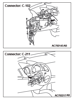
Key Reminder Switch and KOS-ECU Circuit
DTC SET CONDITION
When the ignition push switch is pressed, the steering lock unit communicates with KOS-ECU to unlock the IG knob. However, if there is a failure shown below, the corresponding DTC is set.
- B2402: System ID (vehicle specific code) failure
- B2403: Cyclic Redundancy Check (CRC): The error detection strategy to detect a continuously occurring error (burst error), the calculation result discrepancy
- B2404: Function code failure
- B2405: Rolling code (automatically changing a code for lock/unlock each time when a lock operation is performed)
- B2406: PTC thermistor continuously activated or activated to prevent solenoid abnormal heating on the communication with steering lock unit
- B2407: EEPROM failure
- B2408: Communication error between the steering lock unit and KOS-ECU, or solenoid failure
TECHNICAL DESCRIPTION (COMMENT)
Range of check
- When the IG knob unlock communication is performed by pressing the ignition push switch
Judgment criteria
- B2402: Steering lock unit communication error (system ID) or received system ID error
- B2403: Steering lock unit communication error (CRC) or received frame CRC calculation result discrepancy
- B2404: Steering lock unit communication error (function code) or received frame function code undefined
- B2405: Steering lock unit communication error (rolling code) or received rolling code out of the permissible range
- B2406: Steering lock unit communication error (PTC operation) or PTC thermistor activated to prevent solenoid abnormal heating
- B2407: Steering lock unit communication error (EEPROM) or RRPROM failure
- B2408: Steering lock unit communication error (solenoid) or solenoid failure
TROUBLESHOOTING HINTS
- Malfunction of the key reminder switch (integrated into the steering lock unit)
- Wiring harness or connector failure of CAN bus line
- Malfunction of the KOS-ECU
DIAGNOSIS
Required Special Tools:
- MB991958: Scan Tool (M.U.T.-III Sub Assembly)
- MB991824: Vehicles Communication Interface (V.C.I.)
- MB991827: M.U.T.-III USB Cable
- MB991910: M.U.T.-III Main Harness A (Vehicles with CAN communication system)
STEP 1. Using scan tool MB991958, diagnose the CAN bus line.
CAUTION To prevent damage to scan tool (MB991958), always turn the ignition switch to the "LOCK" (OFF) position before connecting or disconnecting scan tool (MB991958).
- Connect scan tool MB991958 to the data link connector.
- Turn the ignition switch to the "ON" position.
- Diagnose the CAN bus line.
- Turn the ignition switch to the "LOCK" (OFF) position.
Q: Is the CAN bus line found to be normal?
YES : Go to Step 2.
NO : Repair the CAN bus line.
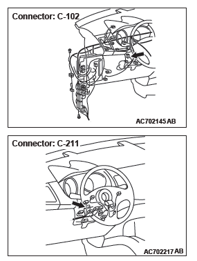
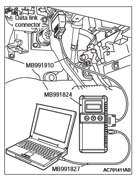
STEP 2. Check key reminder switch connector C-211 and KOS-ECU connector C-102 for loose, corroded or damaged terminals, or terminals pushed back in the connector.
Q: Is the key reminder switch connector C-211 and KOS-ECU connector C-102 in good condition?
YES : Go to Step 3.
NO : Repair the defective connector.
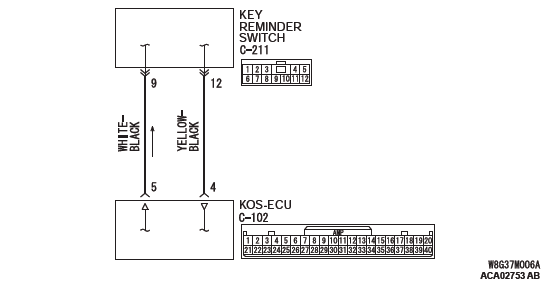
STEP 3. Check the wiring harness between the key reminder switch connector C-211 (terminal No. 12, 9) and the KOS-ECU connector C-102 (terminal No. 4, 5).
Check the signal lines for open circuit and short circuit.
Q: Is the wiring harness between key reminder switch connector C-211 (terminal No. 12, 9) and the KOS-ECU connector C-102 (terminal No. 4, 5) in good condition?
YES : Go to Step 4.
NO : The wiring harness may be damaged or the connector(s) may have loose, corroded or damaged terminals, or terminals pushed back in the connector.
Repair the wiring harness as necessary.
STEP 4. Replace the key reminder switch, and check whether the diagnostic trouble code is reset.
- Erase the DTC.
- Turn the ignition switch from the "LOCK" (OFF) position to the "ON" position.
- Check if the DTC is set.
Q: Is the DTC set?
YES : Replace KOS-ECU and register the ID codes. NO : The trouble can be an intermittent malfunction.
DTC B2409: STL unit comm.(No response)
CAUTION
- If the DTC B2409 is set, diagnose the CAN bus lines.
- Whenever the steering lock unit is replaced, ensure that the communication circuit is normal.
Key Reminder Switch and KOS-ECU Circuit
DTC SET CONDITION
When the ignition push switch is pressed, the steering lock unit communicates with KOS-ECU to unlock the IG knob. If the steering lock unit communication error (no response) occurs at this time, the DTC is set.
TECHNICAL DESCRIPTION (COMMENT)
When the IG knob unlock communication is performed by pressing the ignition push switch, if the steering lock unit communication error (no response) occurs, the steering lock unit is judged as abnormal.
TROUBLESHOOTING HINTS
- Malfunction of the key reminder switch (integrated into the steering lock unit)
- Wiring harness or connector failure of CAN bus line
- Malfunction of the KOS-ECU
DIAGNOSIS
Required Special Tools:
- MB991958: Scan Tool (M.U.T.-III Sub Assembly)
- MB991824: Vehicles Communication Interface (V.C.I.)
- MB991827: M.U.T.-III USB Cable
- MB991910: M.U.T.-III Main Harness A (Vehicles with CAN communication system)
STEP 1. Using scan tool MB991958, diagnose the CAN bus line.
CAUTION To prevent damage to scan tool (MB991958), always turn the ignition switch to the "LOCK" (OFF) position before connecting or disconnecting scan tool (MB991958).
- Connect scan tool MB991958 to the data link connector.
- Turn the ignition switch to the "ON" position.
- Diagnose the CAN bus line.
- Turn the ignition switch to the "LOCK" (OFF) position.
Q: Is the CAN bus line found to be normal?
YES : Go to Step 2.
NO : Repair the CAN bus line.
STEP 2. Check key reminder switch connector C-211 and KOS-ECU connector C-102 for loose, corroded or damaged terminals, or terminals pushed back in the connector.
Q: Is the key reminder switch connector C-211 and KOS-ECU connector C-102 in good condition?
YES : Go to Step 3.
NO : Repair the defective connector.
STEP 3. Check the wiring harness between the key reminder switch connector C-211 (terminal No. 12, 9, 11) and the KOS-ECU connector C-102 (terminal No. 4, 5, 31).
Check the signal lines for open circuit and short circuit.
Q: Is the wiring harness between key reminder switch connector C-211 (terminal No. 12, 9, 11) and the KOS-ECU connector C-102 (terminal No. 4, 5, 31) in good condition?
YES : Go to Step 4.
NO : The wiring harness may be damaged or the connector(s) may have loose, corroded or damaged terminals, or terminals pushed back in the connector.
Repair the wiring harness as necessary.
STEP 4. Replace the key reminder switch, and check whether the diagnostic trouble code is reset.
- Erase the DTC.
- Turn the ignition switch from the "LOCK" (OFF) position to the "ON" position.
- Check if the DTC is set.
Q: Is the DTC set?
YES : Replace KOS-ECU and register the ID codes.
NO : The trouble can be an intermittent malfunction.
DTC B240A DR side antenna(outdoor) open
CAUTION When replacing the ECU, always check that the communication circuit is normal.
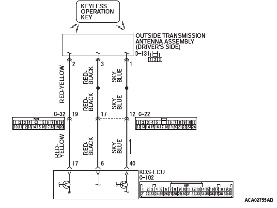
Outside Transmission Antenna assembly (Driver's Side) Circuit
DIAGNOSTIC FUNCTION
If an open circuit is detected in the outside transmission antenna assembly (driver's side), the diagnostic trouble code is set.
JUDGMENT CRITERIA
When the ignition push switch is pressed, or when the antenna open circuit detection request is received from the diagnosis function, the failure is detected.
PROBABLE CAUSES
- Malfunction of the outside transmission antenna assembly (driver's side)
- Malfunction of the KOS-ECU
- Damaged wiring harness and connectors
DIAGNOSTIC PROCEDURE
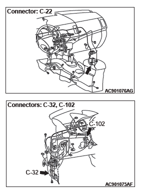
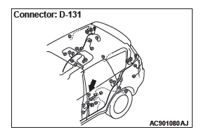
STEP 1. Check KOS-ECU connector C-102 and outside transmission antenna assembly (driver's side) connector D-131 for loose, corroded or damaged terminals, or terminals pushed back in the connector.
Q: Are KOS-ECU connector C-102 and outside transmission antenna assembly (driver's side) connector D-131 in good condition?
YES : Go to Step 2.
NO : Repair or replace the damaged component(s).
STEP 2. Check the wiring harness between KOS-ECU connector C-102 (terminal Nos. 6, 17 and 40) and outside transmission antenna assembly (driver's side) connector D-131 (terminal Nos. 3, 2 and 1).
Check the communication, power supply, and ground wires for open circuit.
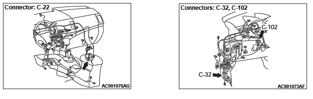
NOTE: Also check intermediate connectors C-22 and C-32 for loose, corroded, or damaged terminals, or terminals pushed back in the connector. If intermediate connectors C-22 and C-32 is damaged, repair or replace the damaged component(s) as described in GROUP 00E, Harness Connector Inspection.
Q: Is the wiring harness between KOS-ECU connector C-102 (terminal Nos. 6, 17 and 40) and outside transmission antenna assembly (driver's side) connector D-131 (terminal Nos. 3, 2 and 1) in good condition?
YES : Go to Step 3.
NO : The wiring harness may be damaged or the connector(s) may have loose, corroded or damaged terminals, or terminals pushed back in the connector.
Repair the wiring harness as necessary.
STEP 3. Keyless operation system communication test Check that the communication with the outside transmission antenna assembly (driver's side) is normal.
Antennas to be checked
Driver side antenna (exterior)
OK: Normal is displayed.
Q: Is the check result normal?
YES : Go to Step 4.
NO : Replace the outside transmission antenna assembly (driver's side).
STEP 4. Check whether the diagnostic trouble code is reset.
- Erase the diagnostic trouble code.
- Turn the ignition switch from the LOCK (OFF) position to the ON position.
- Check if the diagnostic trouble code is set.
Q: Is the diagnostic trouble code set?
YES : Replace KOS-ECU and register the ID codes.
NO : Intermittent malfunction is suspected.
DTC B240B PS side antenna(outdoor) open
CAUTION When replacing the ECU, always check that the communication circuit is normal.
Outside Transmission Antenna assembly (Passenger's Side) Circuit
DIAGNOSTIC FUNCTION
If an open circuit is detected in the exterior transmitter antenna (passenger's side), the diagnostic trouble code is set.
JUDGMENT CRITERIA
When the ignition push switch is pressed, or when the antenna open circuit detection request is received from the diagnosis function, the failure is detected.
PROBABLE CAUSES
- Malfunction of the outside transmission antenna assembly (passenger's side)
- Malfunction of the KOS-ECU
- Damaged wiring harness and connectors
DIAGNOSTIC PROCEDURE
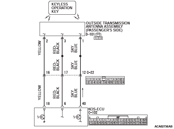
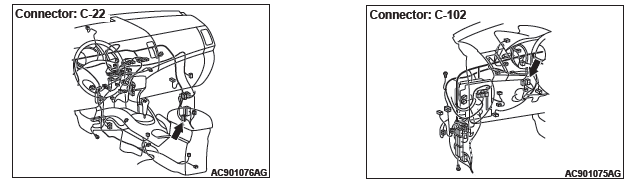
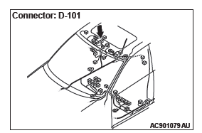
STEP 1. Check KOS-ECU connector C-102 and outside transmission antenna assembly (passenger's side) connector D-101 for loose, corroded or damaged terminals, or terminals pushed back in the connector.
Q: Are KOS-ECU connector C-102 and outside transmission antenna assembly (passenger's side) connector D-101 in good condition?
YES : Go to Step 2.
NO : Repair or replace the damaged component(s).
STEP 2. Check the wiring harness between KOS-ECU connector C-102 (terminal Nos. 6, 18 and 40) and outside transmission antenna assembly (passenger's side) connector D-101 (terminal Nos. 3, 2 and 1).
Check the communication, power supply, and ground wires for open circuit.
NOTE: Also check intermediate connector C-22 for loose, corroded, or damaged terminals, or terminals pushed back in the connector. If intermediate connectors C-22 is damaged, repair or replace the damaged component(s) as described in GROUP 00E, Harness Connector Inspection.
Q: Is the wiring harness between KOS-ECU connector C-102 (terminal Nos. 6, 18 and 40) and outside transmission antenna assembly (passenger's side) connector D-101 (terminal Nos. 3, 2 and 1) in good condition?
YES : Go to Step 3.
NO : The wiring harness may be damaged or the connector(s) may have loose, corroded or damaged terminals, or terminals pushed back in the connector.
Repair the wiring harness as necessary.
STEP 3. Keyless operation system communication test
Check that the communication with the outside transmission antenna assembly (passenger's side) is normal.
Antennas to be checked
passenger side antenna (exterior)
OK: Normal is displayed.
Q: Is the check result normal?
YES : Go to Step 4.
NO : Replace the outside transmission antenna assembly (passenger's side).
STEP 4. Check whether the diagnostic trouble code is reset.
- Erase the diagnostic trouble code.
- Turn the ignition switch from the LOCK (OFF) position to the ON position.
- Check if the diagnostic trouble code is set.
Q: Is the diagnostic trouble code set?
YES : Replace KOS-ECU and register the ID codes.
NO : Intermittent malfunction is suspected .
DTC B240C Liftgate antenna(outdoor) open
CAUTION When replacing the ECU, always check that the communication circuit is normal.
Outside Transmission Antenna assembly (Liftgate) Circuit
DIAGNOSTIC FUNCTION
If an open circuit is detected in the exterior transmitter antenna (liftgate), the diagnostic trouble code is set.
JUDGMENT CRITERIA
When the ignition push switch is pressed, or when the antenna open circuit detection request is received from the diagnosis function, the failure is detected.
PROBABLE CAUSES
- Malfunction of the outside transmission antenna assembly (liftgate)
- Malfunction of the KOS-ECU
- Damaged wiring harness and connectors
DIAGNOSTIC PROCEDURE
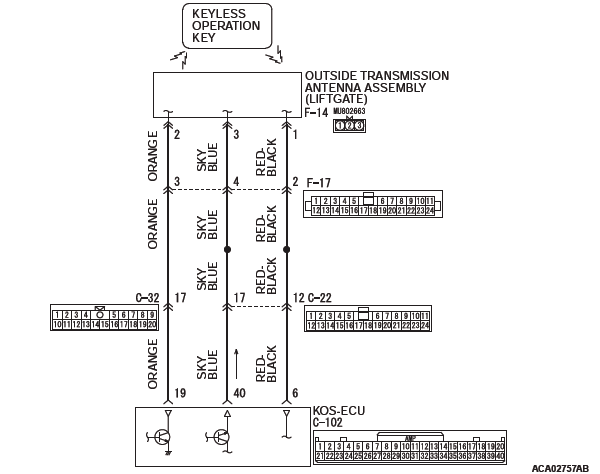
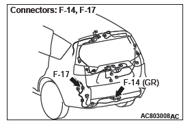
STEP 1. Check KOS-ECU connector C-102 and outside transmission antenna assembly (liftgate) connector F-14 for loose, corroded or damaged terminals, or terminals pushed back in the connector.
Q: Are KOS-ECU connector C-102 and outside transmission antenna assembly (liftgate) connector D-101 in good condition?
YES : Go to Step 2.
NO : Repair or replace the damaged component(s).
STEP 2. Check the wiring harness between KOS-ECU connector C-102 (terminal Nos. 6, 19 and 40) and outside transmission antenna assembly (liftgate) connector F-14(terminal Nos. 1, 2 and 3).
Check the communication, power supply, and ground wires for open circuit.
NOTE: Also check intermediate connectors C-22, C-32 and F-17 for loose, corroded, or damaged terminals, or terminals pushed back in the connector. If intermediate connectors C-22, C-32 and F-17 is damaged, repair or replace the damaged component(s) as described in GROUP 00E, Harness Connector Inspection.
Q: Is the wiring harness between KOS-ECU connector C-102 (terminal Nos. 6, 19 and 40) and outside transmission antenna assembly (liftgate) connector F-14(terminal Nos. 1, 2 and 3) in good condition?
YES : Go to Step 3.
NO : The wiring harness may be damaged or the connector(s) may have loose, corroded or damaged terminals, or terminals pushed back in the connector.
Repair the wiring harness as necessary.
STEP 3. Keyless operation system communication test
Check that the communication with the outside transmission antenna assembly (liftgate) is normal.
Antennas to be checked
liftgate side antenna (exterior)
OK: Normal is displayed.
Q: Is the check result normal?
YES : Go to Step 4.
NO : Replace the outside transmission antenna assembly (liftgate).
STEP 4. Check whether the diagnostic trouble code is reset.
- Erase the diagnostic trouble code.
- Turn the ignition switch from the LOCK (OFF) position to the ON position.
- Check if the diagnostic trouble code is set.
Q: Is the diagnostic trouble code set?
YES : Replace KOS-ECU and register the ID codes.
NO : Intermittent malfunction is suspected.
DTC B240D Front antenna(indoor) open
CAUTION When replacing the ECU, always check that the communication circuit is normal.
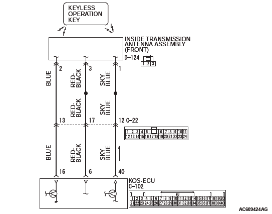
Inside Transmission Antenna assembly (Front) Circuit
DIAGNOSTIC FUNCTION
If an open circuit is detected in the inside transmission antenna assembly (front), the diagnostic trouble code is set.
JUDGMENT CRITERIA
When the ignition push switch is pressed, or when the antenna open circuit detection request is received from the diagnosis function, the failure is detected.
PROBABLE CAUSES
- Malfunction of the inside transmission antenna assembly (front)
- Malfunction of the KOS-ECU
- Damaged wiring harness and connectors
DIAGNOSTIC PROCEDURE
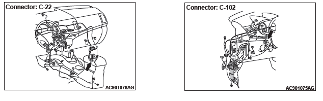
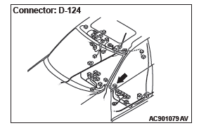
STEP 1. Check KOS-ECU connector C-102 and inside transmission antenna assembly (front) connector D-124 for loose, corroded or damaged terminals, or terminals pushed back in the connector.
Q: Are KOS-ECU connector C-102 and inside transmission antenna assembly (front) connector D-124 in good condition?
YES : Go to Step 2.
NO : Repair or replace the damaged component(s).
STEP 2. Check the wiring harness between KOS-ECU connector C-102 (terminal Nos. 6, 16 and 40) and inside transmission antenna assembly (front) connector D-124 (terminal Nos. 3, 2 and 1).
Check the communication, power supply, and ground wires for open circuit.
NOTE: Also check intermediate connector C-22 for loose, corroded, or damaged terminals, or terminals pushed back in the connector. If intermediate connectors C-22 is damaged, repair or replace the damaged component(s) as described in GROUP 00E, Harness Connector Inspection.
Q: Is the wiring harness between KOS-ECU connector C-102 (terminal Nos. 6, 18 and 40) and inside transmission antenna assembly (front) connector D-124 (terminal Nos. 3, 2 and 1) in good condition?
YES : Go to Step 3.
NO : The wiring harness may be damaged or the connector(s) may have loose, corroded or damaged terminals, or terminals pushed back in the connector.
Repair the wiring harness as necessary.
STEP 3. Keyless operation system communication test
Check that the communication with the inside transmission antenna assembly (front) is normal.
Antennas to be checked
Driver's side antenna (interior)
OK: Normal is displayed.
Q: Is the check result normal?
YES : Go to Step 4.
NO : Replace the inside transmission antenna assembly (front).
STEP 4. Check whether the diagnostic trouble code is reset.
- Erase the diagnostic trouble code.
- Turn the ignition switch from the LOCK (OFF) position to the ON position.
- Check if the diagnostic trouble code is set.
Q: Is the diagnostic trouble code set?
YES : Replace KOS-ECU and register the ID codes.
NO : Intermittent malfunction is suspected.
DTC B240E RR antenna(indoor) open
CAUTION When replacing the ECU, always check that the communication circuit is normal.
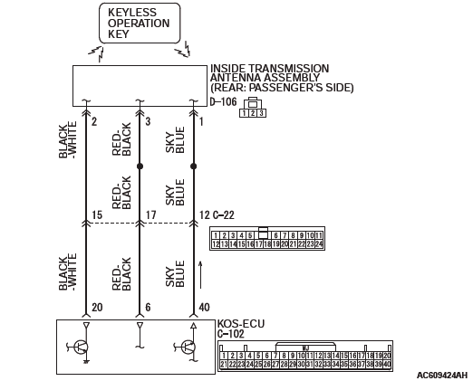
Inside Transmission Antenna assembly (Rear: Passenger's Side) Circuit
DIAGNOSTIC FUNCTION
If an open circuit is detected in the inside transmission antenna assembly (rear: passenger's side), the diagnostic trouble code is set.
JUDGMENT CRITERIA
When the ignition push switch is pressed, or when the antenna open circuit detection request is received from the diagnosis function, the failure is detected.
PROBABLE CAUSES
- Malfunction of inside transmission antenna assembly (rear: passenger's side)
- Malfunction of the KOS-ECU
- Damaged wiring harness and connectors
DIAGNOSTIC PROCEDURE
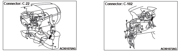
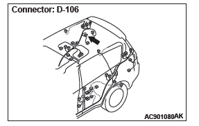
STEP 1. Check KOS-ECU connector C-102 and inside transmission antenna assembly (rear: passenger's side) connector D-106 for loose, corroded or damaged terminals, or terminals pushed back in the connector.
Q: Are KOS-ECU connector C-102 and inside transmission antenna assembly (rear: passenger's side) connector D-106 in good condition?
YES : Go to Step 2.
NO : Repair or replace the damaged component(s).
STEP 2. Check the wiring harness between KOS-ECU connector C-102 (terminal Nos. 6, 20 and 40) and inside transmission antenna assembly (rear: passenger's side) connector D-106 (terminal Nos. 3, 2 and 1).
Check the communication, power supply, and ground wires for open circuit.
NOTE: Also check intermediate connector C-22 for loose, corroded, or damaged terminals, or terminals pushed back in the connector. If intermediate connectors C-22 is damaged, repair or replace the damaged component(s) as described in GROUP 00E, Harness Connector Inspection.
Q: Is the wiring harness between KOS-ECU connector C-102 (terminal Nos. 6, 20 and 40) and inside transmission antenna assembly (rear: passenger's side) connector D-106 (terminal Nos. 3, 2 and 1) in good condition?
YES : Go to Step 3.
NO : The wiring harness may be damaged or the connector(s) may have loose, corroded or damaged terminals, or terminals pushed back in the connector.
Repair the wiring harness as necessary.
STEP 3. Keyless operation system communication test
Check that the communication with the inside transmission antenna assembly (rear: passenger's side) is normal.
Antennas to be checked
Rear front passenger's side antenna (interior)
OK: Normal is displayed.
Q: Is the check result normal?
YES : Go to Step 4.
NO : Replace the inside transmission antenna assembly (rear: passenger's side).
STEP 4. Check whether the diagnostic trouble code is reset.
- Erase the diagnostic trouble code.
- Turn the ignition switch from the LOCK (OFF) position to the ON position.
- Check if the diagnostic trouble code is set.
Q: Is the diagnostic trouble code set?
YES : Replace KOS-ECU and register the ID codes.
NO : Intermittent malfunction is suspected.
READ NEXT:
 DTC B2412, B2413, B2415, B2416, C1608, C1900, C1901, C1910, C1920, C1930, C1940,
C1911, C1921, C1931, C1941, C1912, C1922, C1932, C1942, C1913, C1923, C1933,
C1943, C1914, C1924, C1934, C1944
DTC B2412, B2413, B2415, B2416, C1608, C1900, C1901, C1910, C1920, C1930, C1940,
C1911, C1921, C1931, C1941, C1912, C1922, C1932, C1942, C1913, C1923, C1933,
C1943, C1914, C1924, C1934, C1944
DTC B2412 Antenna power voltage
CAUTION
If diagnostic trouble code No. B2412 is set,
diagnose the CAN bus lines.
When replacing the ECU, always check that
the communication circuit is normal.
An
DTC C1915, C1925, C1935, C1945, U0019, U0141, U0151, U0154, U0155, U0164, U0184,
U0245, U1412, U1415, U1417
DTC C1915: Transmitter OFF mode 1
DTC C1925: Transmitter OFF mode 2
DTC C1935: Transmitter OFF mode 3
DTC C1945: Transmitter OFF mode 4
CAUTION
If there is any problem in the CAN bus lines, an incorre
Inspection Procedure 1-9
Inspection Procedure 1: Cannot communicate with KOS-ECU using the scan
tool.
CAUTION
Before replacing the ECU, ensure that the communication
circuit is normal.
TECHNICAL DESCRIPTION (COMMENT)
If the
SEE MORE:
DTC C1915, C1925, C1935, C1945, U0019, U0141, U0151, U0154, U0155, U0164, U0184,
U0245, U1412, U1415, U1417
DTC C1915: Transmitter OFF mode 1
DTC C1925: Transmitter OFF mode 2
DTC C1935: Transmitter OFF mode 3
DTC C1945: Transmitter OFF mode 4
CAUTION
If there is any problem in the CAN bus lines, an incorrect
diagnostic trouble code may be set. Prior to this diagnosis,
diagnose the CAN bus lines.
DTC SET
Intake and Exhaust
Service Specifications
Special Tools
Intake and Exhaust
Diagnosis
INTRODUCTION
Intake leaks usually create driveability issues that
are not obviously related to the intake system.
Exhaust leaks or abnormal noise is caused by
cracks, gaskets and fittings, or by exhaust pipe or
muffler damage due
