Mitsubishi Outlander: DTC C1041, C1042, C1043, C1044, C1046, C1047, C1048, C1049, C104B, C104F, C1053, C1057, C105F, C1063, C1067, C105B
DTC C1041: Abnormality in periodical signal for FL wheel speed sensor
CAUTION
- If there is any problem in the CAN bus lines, an incorrect DTC may be set. Prior to this diagnosis, diagnose the CAN bus lines (Refer to GROUP 54C − CAN Bus Line Diagnostic Flow).
- Whenever ECU is replaced, ensure that the CAN bus lines are normal.
CIRCUIT OPERATION
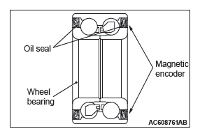
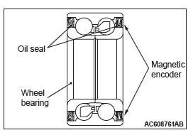
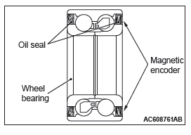
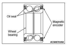
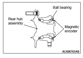
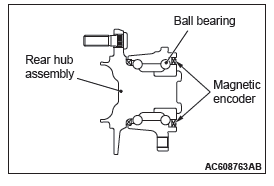
- The wheel speed sensor is a kind of a pulse generator. It consists of encoders (a plate on which north and south pole sides of the magnets are arranged alternately) for detecting the wheel speed which rotates at the same speed of the wheels and wheel speed sensors. This sensor outputs frequency pulse signals in proportion to the wheel speed.
- The pulse signals, which the wheel speed sensor creates, are sent to ABS-ECU. ABS-ECU uses the frequency of the pulse signals to determine the wheel speed.
DTC SET CONDITIONS
ABS-ECU monitors the signals from each wheel speed sensor while the vehicle is being driven. If any periodical drop is found in these sensor signals, ABS-ECU will set the relevant DTC.
PROBABLE CAUSES
Current trouble
- Excessive gap between the wheel speed sensor and the magnetic encoder for wheel speed detection
- Wheel bearing malfunction
- Deformation of the magnetic encoder for wheel speed detection
- Adhesion of foreign materials on the wheel speed sensor
- Adhesion of foreign materials on the magnetic encoder for wheel speed detection
- Malfunction of wheel speed sensor
- Improper installation of the wheel speed sensor
- ABS-ECU malfunction
- Disturbance of magnetization pattern for magnetic encoder for wheel speed detection
- The number of poles on the magnetic encoder for wheel speed detection (the number of N-pole and S-pole) is changed.
Past trouble
- When the diagnostic trouble code No. C100A is also set, carry out diagnosis with particular emphasis on wiring harness and connector failures between ABS-ECU and the wheel speed sensor. For diagnosis procedures, refer to How to treat past trouble (GROUP 00 − How to Use Troubleshooting/ How to Treat Past Trouble).
- When the diagnostic trouble code No. C100A is not set, the
following conditions may be present:
- Some wheels slip.
- Unstable vehicle attitude
- External noise interference
- Vehicle ran with the parking brake applied.
- Only two wheels are rotated on a drum tester.
DIAGNOSIS
Required Special Tools:
- MB991958: Scan Tool (M.U.T.-III Sub Assembly)
- MB991824: Vehicle Communication Interface (V.C.I.)
- MB991827: M.U.T.-III USB Cable
- MB991910: M.U.T.-III Main Harness A
STEP 1. Using scan tool MB991958, diagnose the CAN bus lines.
Use scan tool to diagnose the CAN bus lines.
Q: Is the check result normal?
YES : Go to Step 3.
NO : Repair the CAN bus lines (Refer to GROUP 54C − CAN Bus Diagnostics Table). On completion, go to Step 2.
STEP 2. DTC recheck after resetting CAN bus lines
Q: Is DTC C1041 set?
YES : Go to Step 3.
NO : The procedure is complete.
STEP 3. Using scan tool MB991958, check the DTC
Check that the DTC C100A is also set.
Q: Is DTC C100A also set?
YES : Perform the diagnosis for the DTC C100A.
NO : Go to Step 4.
STEP 4. Check wheel speed sensor <FL> installation
Check how the wheel speed sensor <FL> is installed (Disconnection of wheel speed sensor <FL>, loose mounting bolt, etc.).
Q: Is the check result normal?
YES : Go to Step 5.
NO : Reinstall the wheel speed sensor <FL> correctly. Then go to Step 5.
STEP 5. Check for wheel speed sensor <FL> output current
Q: Is the check result normal?
YES : Go to Step 6.
NO : Replace the wheel speed sensor <FL>. Then go to Step 9.
STEP 6. Check for wheel bearing looseness
NOTE:
- Loose wheel bearing may increase the gap between the wheel speed sensor <FL> and the wheel speed detection magnet encoder.
- Check the wheel bearing <FL> for looseness (Refer to GROUP 26 − Wheel Bearing Play Check).
Q: Is the check result normal?
YES : Go to Step 7.
NO : Replace the wheel bearing <FL> (Refer to GROUP 26 − Front Axle Hub Assembly). Then go to Step 10.
STEP 7. Check wheel speed detection encoder
Check the encoder for adhesion of foreign materials or deformation.
Q: Is the check result normal?
YES : Go to Step 8.
NO (Adhesion of foreign materials) : Remove the foreign materials and clean the encoder so as not to disturb the magnetization pattern on it while taking care of the magnet, magnetic substance, and magnetic attraction. Then go to Step 10.
NO (Deformation) : Replace the wheel bearing <FL> (Refer to GROUP 26 − Front Axle Hub Assembly). Then go to Step 10.
STEP 8. Check whether the DTC is reset.
- Erase the DTC.
- Drive the vehicle at 12mph (20 km/h) or higher.
NOTE: The ABS warning light does not turn OFF in some cases unless the vehicle runs at 12mph (20 km/h) or higher.
Q: Is DTC C1041 set?
YES : Replace the wheel speed sensor <FL>. Then go to Step 9.
NO : Intermittent malfunction (Refer to GROUP 00 − How to Use Troubleshooting/How to Cope with Intermittent Malfunctions).
STEP 9. Check whether the DTC is reset.
- Erase the DTC.
- Drive the vehicle at 12mph (20 km/h) or higher.
NOTE: The ABS warning light does not turn OFF in some cases unless the vehicle runs at 12mph (20 km/h) or higher.
Q: Is DTC C1041 set?
YES : Replace the hydraulic unit (integrated with ABS-ECU). Then go to Step 10.
NO : The procedure is complete.
STEP 10. Check whether the DTC is reset.
- Erase the DTC.
- Drive the vehicle at 12mph (20 km/h) or higher.
NOTE: The ABS warning light does not turn OFF in some cases unless the vehicle runs at 12mph (20 km/h) or higher.
Q: Is DTC C1041 set?
YES : Return to Step 1.
NO : The procedure is complete.
DTC C1042: Abnormality in periodical signal for FR wheel speed sensor
CAUTION
- If there is any problem in the CAN bus lines, an incorrect DTC may be set. Prior to this diagnosis, diagnose the CAN bus lines (Refer to GROUP 54C − CAN Bus Line Diagnostic Flow).
- Whenever ECU is replaced, ensure that the CAN bus lines are normal.
CIRCUIT OPERATION
- The wheel speed sensor is a kind of a pulse generator. It consists of encoders (a plate on which north and south pole sides of the magnets are arranged alternately) for detecting the wheel speed which rotates at the same speed of the wheels and wheel speed sensors. This sensor outputs frequency pulse signals in proportion to the wheel speed.
- The pulse signals, which the wheel speed sensor creates, are sent to ABS-ECU. ABS-ECU uses the frequency of the pulse signals to determine the wheel speed.
DTC SET CONDITIONS
ASC-ECU monitors the signals from each wheel speed sensor while the vehicle is being driven. If any periodical drop is found in these sensor signals, ASC-ECU will set the relevant DTC.
PROBABLE CAUSES
Current trouble
- Excessive gap between the wheel speed sensor and the magnetic encoder for wheel speed detection
- Wheel bearing malfunction
- Deformation of the magnetic encoder for wheel speed detection
- Adhesion of foreign materials on the wheel speed sensor
- Adhesion of foreign materials on the magnetic encoder for wheel speed detection
- Malfunction of wheel speed sensor
- Improper installation of the wheel speed sensor
- ABS-ECU malfunction
- Disturbance of magnetization pattern for magnetic encoder for wheel speed detection
- The number of poles on the magnetic encoder for wheel speed detection (the number of N-pole and S-pole) is changed.
Past trouble
- When the diagnostic trouble code No. C1015 is also set, carry out diagnosis with particular emphasis on wiring harness and connector failures between ABS-ECU and the wheel speed sensor. For diagnosis procedures, refer to How to treat past trouble (GROUP 00 − How to Use Troubleshooting/ How to Treat Past Trouble).
- When diagnostic trouble code No. C1015 is not set, the following
conditions may be present:
- Some wheels slip.
- Unstable vehicle attitude
- External noise interference
- Vehicle ran with the parking brake applied.
- Only two wheels are rotated on a drum tester.
DIAGNOSIS
Required Special Tools:
- MB991958: Scan Tool (M.U.T.-III Sub Assembly)
- MB991824: Vehicle Communication Interface (V.C.I.)
- MB991827: M.U.T.-III USB Cable
- MB991910: M.U.T.-III Main Harness A
STEP 1. Using scan tool MB991958, diagnose the CAN bus lines.
Use scan tool to diagnose the CAN bus lines.
Q: Is the check result normal?
YES : Go to Step 3.
NO : Repair the CAN bus lines (Refer to GROUP 54C − CAN Bus Diagnostics Table). On completion, go to Step 2.
STEP 2. DTC recheck after resetting CAN bus lines
Q: Is DTC C1042 set?
YES : Go to Step 3.
NO : The procedure is complete.
STEP 3. Using scan tool MB991958, check the DTC
Check that the DTC C1015 is also set.
Q: Is DTC C1015 also set?
YES : Perform the diagnosis for the DTC C1015.
NO : Go to Step 4.
STEP 4. Check wheel speed sensor <FR> installation
Check how the wheel speed sensor <FR> is installed (Disconnection of wheel speed sensor <FR>, loose mounting bolt, etc.).
Q: Is the check result normal?
YES : Go to Step 5.
NO : Reinstall the wheel speed sensor <FR> correctly. Then go to Step 5.
STEP 5. Check for wheel speed sensor <FR> output current
Q: Is the check result normal?
YES : Go to Step 6.
NO : Replace the wheel speed sensor <FR>. Then go to Step 9.
STEP 6. Check for wheel bearing looseness
NOTE:
- Loose wheel bearing may increase the gap between the wheel speed sensor <FR> and the wheel speed detection magnet encoder.
- Check the wheel bearing <FR> for looseness (Refer to GROUP 26 − On-vehicle Service).
Q: Is the check result normal?
YES : Go to Step 7.
NO : Replace the wheel bearing <FR> (Refer to GROUP 26 − Front Axle Hub Assembly). Then go to Step 10.
STEP 7. Check wheel speed detection encoder
Check the encoder for adhesion of foreign materials or deformation.
Q: Is the check result normal?
YES : Go to Step 8.
NO (Adhesion of foreign materials) : Remove the foreign materials and clean the encoder so as not to disturb the magnetization pattern on it while taking care of the magnet, magnetic substance, and magnetic attraction. Then go to Step 10.
NO (Deformation) : Replace the wheel bearing <FR> (Refer to GROUP 26 − Front Axle Hub Assembly). Then go to Step 10.
STEP 8. Check whether the DTC is reset.
- Erase the DTC.
- Drive the vehicle at 12mph (20 km/h) or higher.
NOTE: The ABS warning light does not turn OFF in some cases unless the vehicle runs at 12mph (20 km/h) or higher.
Q: Is DTC C1042 set?
YES : Replace the wheel speed sensor <FR>. Then go to Step 9.
NO : Intermittent malfunction (Refer to GROUP 00 − How to Use Troubleshooting/How to Cope with Intermittent Malfunctions).
STEP 9. Check whether the DTC is reset.
- Erase the DTC.
- Drive the vehicle at 12mph (20 km/h) or higher.
NOTE: The ABS warning light does not turn OFF in some cases unless the vehicle runs at 12mph (20 km/h) or higher.
Q: Is DTC C1042 set?
YES : Replace the hydraulic unit (integrated with ABS-ECU). Then go to Step 10.
NO : The procedure is complete.
STEP 10. Check whether the DTC is reset.
- Erase the DTC.
- Drive the vehicle at 12mph (20 km/h) or higher.
NOTE: The ABS warning light does not turn OFF in some cases unless the vehicle runs at 12mph (20 km/h) or higher.
Q: Is DTC C1042 set?
YES : Return to Step 1.
NO : The procedure is complete.
DTC C1043: Abnormality in periodical signal for RL wheel speed sensor
CAUTION
- If there is any problem in the CAN bus lines, an incorrect DTC may be set. Prior to this diagnosis, diagnose the CAN bus lines (Refer to GROUP 54C − CAN Bus Line Diagnostic Flow).
- Whenever ECU is replaced, ensure that the CAN bus lines are normal.
CIRCUIT OPERATION
- The wheel speed sensor is a kind of a pulse generator. It consists of encoders (a plate on which north and south pole sides of the magnets are arranged alternately) for detecting the wheel speed which rotates at the same speed of the wheels and wheel speed sensors. This sensor outputs frequency pulse signals in proportion to the wheel speed.
- The pulse signals, which the wheel speed sensor creates, are sent to ABS-ECU. ABS-ECU uses the frequency of the pulse signals to determine the wheel speed.
DTC SET CONDITIONS
ABS-ECU monitors the signals from each wheel speed sensor while the vehicle is being driven. If any periodical drop is found in these sensor signals, ABS-ECU will set the relevant DTC.
PROBABLE CAUSES
Current trouble
- Excessive gap between the wheel speed sensor and the magnetic encoder for wheel speed detection
- Adhesion of foreign materials on the wheel speed sensor
- Wheel bearing malfunction
- Deformation of the magnetic encoder for wheel speed detection
- Adhesion of foreign materials on the magnetic encoder for wheel speed detection
- Malfunction of wheel speed sensor
- Improper installation of the wheel speed sensor
- ABS-ECU malfunction
- Disturbance of magnetization pattern for magnetic encoder for wheel speed detection
- The number of poles on the magnetic encoder for wheel speed detection (the number of N-pole and S-pole) is changed.
Past trouble
- When the diagnostic trouble code No. C1020 is also set, carry out diagnosis with particular emphasis on wiring harness and connector failures between ABS-ECU and the wheel speed sensor. For diagnosis procedures, refer to How to treat past trouble (GROUP 00 − How to Use Troubleshooting/ How to Treat Past Trouble).
- When the diagnostic trouble code No. C1020 is not set, the
following conditions may be present:
- Right or left wheels are rotated.
- Unstable vehicle attitude
- External noise interference
- Vehicle ran with the parking brake applied.
DIAGNOSIS
Required Special Tools:
- MB991958: Scan Tool (M.U.T.-III Sub Assembly)
- MB991824: Vehicle Communication Interface (V.C.I.)
- MB991827: M.U.T.-III USB Cable
- MB991910: M.U.T.-III Main Harness A
STEP 1. Using scan tool MB991958, diagnose the CAN bus lines.
Use scan tool to diagnose the CAN bus lines.
Q: Is the check result normal?
YES : Go to Step 3.
NO : Repair the CAN bus lines. On completion, go to Step 2.
STEP 2. DTC recheck after resetting CAN bus lines
Q: Is DTC C1043 set?
YES : Go to Step 3.
NO : The procedure is complete.
STEP 3. Using scan tool MB991958, check the DTC
Check that the DTC C1020 is also set.
Q: Is DTC C1020 also set?
YES : Perform the diagnosis for the DTC C1020.
NO : Go to Step 4.
STEP 4. Check wheel speed sensor <RL> installation
Check how the wheel speed sensor <RL> is installed (Disconnection of wheel speed sensor <RL>, loose mounting bolt, etc.).
Q: Is the check result normal?
YES : Go to Step 5.
NO : Reinstall the wheel speed sensor <RL> correctly. Then go to Step 5.
STEP 5. Check for wheel speed sensor <RL> output current
Q: Is the check result normal?
YES : Go to Step 6.
NO : Replace the wheel speed sensor <RL>. Then go to Step 9.
STEP 6. Check for wheel bearing looseness
NOTE:
- Loose wheel bearing may increase the gap between the wheel speed sensor <RL> and the wheel speed detection magnet encoder.
- Check the wheel bearing <RL> for looseness (Refer to GROUP 27A − On-vehicle Service).
Q: Is the check result normal?
YES : Go to Step 7.
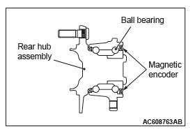
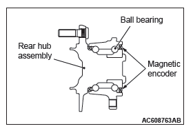
NO : Replace the rear wheel hub assembly <RL> (Refer to GROUP 27A − Rear Axle Hub Assembly).
Then go to Step 10.
STEP 7. Check wheel speed detection encoder
Check the encoder for adhesion of foreign materials or deformation.
Q: Is the check result normal?
YES : Go to Step 8.
NO (Adhesion of foreign materials) : Remove the foreign materials and clean the encoder so as not to disturb the magnetization pattern on it while taking care of the magnet, magnetic substance, and magnetic attraction. Then go to Step 10.
NO (Deformation) : Replace the rear wheel hub assembly <RL> (Refer to GROUP 27A − Rear Axle Hub Assembly). Then go to Step 10.
STEP 8. Check whether the DTC is reset.
- Erase the DTC.
- Drive the vehicle at 12mph (20 km/h) or higher.
NOTE: The ABS warning light does not turn OFF in some cases unless the vehicle runs at 12mph (20 km/h) or higher.
Q: Is DTC C1043 set?
YES : Replace the wheel speed sensor <RL>. Then go to Step 9.
NO : Intermittent malfunction (Refer to GROUP 00 − How to Use Troubleshooting/How to Cope with Intermittent Malfunctions).
STEP 9. Check whether the DTC is reset.
- Erase the DTC.
- Drive the vehicle at 12mph (20 km/h) or higher.
NOTE: The ABS warning light does not turn OFF in some cases unless the vehicle runs at 12mph (20 km/h) or higher.
Q: Is DTC C1043 set?
YES : Replace the hydraulic unit (integrated with ABS-ECU). Then go to Step 10.
NO : The procedure is complete.
STEP 10. Check whether the DTC is reset.
- Erase the DTC.
- Drive the vehicle at 12mph (20 km/h) or higher.
NOTE: The ABS warning light does not turn OFF in some cases unless the vehicle runs at 12mph (20 km/h) or higher.
Q: Is DTC C1043 set?
YES : Return to Step 1.
NO : The procedure is complete.
DTC C1044: Abnormality in periodical signal for RR wheel speed sensor
CAUTION
- If there is any problem in the CAN bus lines, an incorrect DTC may be set. Prior to this diagnosis, diagnose the CAN bus lines (Refer to GROUP 54C − CAN Bus Line Diagnostic Flow).
- Whenever ECU is replaced, ensure that the CAN bus lines are normal.
CIRCUIT OPERATION
- The wheel speed sensor is a kind of a pulse generator. It consists of encoders (a plate on which north and south pole sides of the magnets are arranged alternately) for detecting the wheel speed which rotates at the same speed of the wheels and wheel speed sensors. This sensor outputs frequency pulse signals in proportion to the wheel speed.
- The pulse signals, which the wheel speed sensor creates, are sent to ABS-ECU. ABS-ECU uses the frequency of the pulse signals to determine the wheel speed.
DTC SET CONDITIONS
ABS-ECU monitors the signals from each wheel speed sensor while the vehicle is being driven. If any periodical drop is found in these sensor signals, ABS-ECU will set the relevant DTC.
PROBABLE CAUSES
Current trouble
- Excessive gap between the wheel speed sensor and the magnetic encoder for wheel speed detection
- Adhesion of foreign materials on the wheel speed sensor
- Wheel bearing malfunction
- Deformation of the magnetic encoder for wheel speed detection
- Adhesion of foreign materials on the magnetic encoder for wheel speed detection
- Malfunction of wheel speed sensor
- Improper installation of the wheel speed sensor
- ABS-ECU malfunction
- Disturbance of magnetization pattern for magnetic encoder for wheel speed detection
- The number of poles on the magnetic encoder for wheel speed detection (the number of N-pole and S-pole) is changed.
Past trouble
- When the diagnostic trouble code No.C102B is also set, carry out diagnosis with particular emphasis on wiring harness and connector failures between ABS-ECU and the wheel speed sensor. For diagnosis procedures, refer to How to treat past trouble (GROUP 00 − How to Use Troubleshooting/ How to Treat Past Trouble).
- When the diagnostic trouble code No.C102B is not set, the
following conditions may be present:
- Right or left wheels are rotated.
- Unstable vehicle attitude
- External noise interference
- Vehicle ran with the parking brake applied.
DIAGNOSIS
Required Special Tools:
- MB991958: Scan Tool (M.U.T.-III Sub Assembly)
- MB991824: Vehicle Communication Interface (V.C.I.)
- MB991827: M.U.T.-III USB Cable
- MB991910: M.U.T.-III Main Harness A
STEP 1. Using scan tool MB991958, diagnose the CAN bus lines.
Use scan tool to diagnose the CAN bus lines.
Q: Is the check result normal?
YES : Go to Step 3.
NO : Repair the CAN bus lines (Refer to GROUP 54C − CAN Bus Diagnostics Table). On completion, go to Step 2.
STEP 2. DTC recheck after resetting CAN bus lines
Q: Is DTC C1044 set?
YES : Go to Step 3.
NO : The procedure is complete.
STEP 3. Using scan tool MB991958, check the DTC
Check that the DTC C102B is also set.
Q: Is DTC C102B also set?
YES : Perform the diagnosis for the DTC C102B.
NO : Go to Step 4.
STEP 4. Check wheel speed sensor <RR> installation
Check how the wheel speed sensor <RR> is installed (Disconnection of wheel speed sensor <RR>, loose mounting bolt, etc.).
Q: Is the check result normal?
YES : Go to Step 5.
NO : Reinstall the wheel speed sensor <RR> correctly. Then go to Step 5.
STEP 6. Check for wheel bearing looseness
NOTE:
- Loose wheel bearing may increase the gap between the wheel speed sensor <RR> and the wheel speed detection magnet encoder.
- Check the wheel bearing <RR> for looseness (Refer to GROUP 27A − On-vehicle Service).
Q: Is the check result normal?
YES : Go to Step 7.
NO : Replace the rear wheel hub assembly <RR> (Refer to GROUP 27A − Rear Axle Hub Assembly).
Then go to Step 10.
STEP 7. Check wheel speed detection encoder
Check the encoder for adhesion of foreign materials or deformation.
Q: Is the check result normal?
YES : Go to Step 8.
NO (Adhesion of foreign materials) : Remove the foreign materials and clean the encoder so as not to disturb the magnetization pattern on it while taking care of the magnet, magnetic substance, and magnetic attraction. Then go to Step 10.
NO (Deformation) : Replace the rear wheel hub assembly <RR> (Refer to GROUP 27A − Rear Axle Hub Assembly). Then go to Step 10.
STEP 8. Check whether the DTC is reset.
- Erase the DTC.
- Drive the vehicle at 12mph (20 km/h) or higher.
NOTE: The ABS warning light does not turn OFF in some cases unless the vehicle runs at 12mph (20 km/h) or higher.
Q: Is DTC C1044 set?
YES : Replace the wheel speed sensor <RR>. Then go to Step 9.
NO : Intermittent malfunction (Refer to GROUP 00 − How to Use Troubleshooting/How to Cope with Intermittent Malfunctions).
STEP 9. Check whether the DTC is reset.
- Erase the DTC.
- Drive the vehicle at 12mph (20 km/h) or higher.
NOTE: The ABS warning light does not turn OFF in some cases unless the vehicle runs at 12mph (20 km/h) or higher.
Q: Is DTC C1044 set?
YES : Replace the hydraulic unit (integrated with ABS-ECU). Then go to Step 10.
NO : The procedure is complete.
STEP 10. Check whether the DTC is reset.
- Erase the DTC.
- Drive the vehicle at 12mph (20 km/h) or higher.
NOTE: The ABS warning light does not turn OFF in some cases unless the vehicle runs at 12mph (20 km/h) or higher.
Q: Is DTC C1044 set?
YES : Return to Step 1.
NO : The procedure is complete.
DTC C1046: FL wheel speed sensor control phase time exceeded
Wheel Speed Sensor Circuit
CAUTION If there is any problem in the CAN bus lines, an incorrect DTC may be set. Prior to this diagnosis, diagnose the CAN bus lines (Refer to GROUP 54C − CAN Bus Line Diagnostic Flow).
CIRCUIT OPERATION
- The wheel speed sensor is a type of pulse generator. It consists of encoders (a plate on which north and south pole sides of the magnets are arranged alternately) for detecting the wheel speed which rotates at the same speed of the wheels and wheel speed sensors. This sensor outputs frequency pulse signals in proportion to the wheel speed.
- The pulse signals, which the wheel speed sensor creates, are sent to ABS-ECU. ABS-ECU uses the frequency of the pulse signals to determine the wheel speed.
DTC SET CONDITIONS
This DTC is set if any malfunction below is found:
- When the brake fluid pressure is decreased for a long time.
- When the brake fluid pressure is held for a long time.
PROBABLE CAUSES
- Damaged wiring harness and connectors
- External noise interference
- Malfunction of wheel speed sensor
- ABS-ECU malfunction
- Excessive gap between the wheel speed sensor and the magnetic encoder for wheel speed detection
- Adhesion of foreign materials on the wheel speed sensor
- Adhesion of foreign materials on the magnetic encoder for wheel speed detection
- Wheel bearing malfunction
- Improper installation of the wheel speed sensor
- Deformation of the magnetic encoder for wheel speed detection
- Disturbance of magnetization pattern for magnetic encoder for wheel speed detection
- Missing teeth of the magnetic encoder for wheel speed detection
DIAGNOSIS
Required Special Tools:
- MB991958: Scan Tool (M.U.T.-III Sub Assembly)
- MB991824: Vehicle Communication Interface (V.C.I.)
- MB991827: M.U.T.-III USB Cable
- MB991910: M.U.T.-III Main Harness A
STEP 1. Using scan tool MB991958, diagnose the CAN bus lines.
Use scan tool to diagnose the CAN bus lines.
Q: Is the check result normal?
YES : Go to Step 3.
NO : Repair the CAN bus lines (Refer to GROUP 54C − CAN Bus Diagnostics Table). On completion, go to Step 2.
STEP 2. DTC recheck after resetting CAN bus lines
Q: Is DTC C1046 set?
YES : Go to Step 3.
NO : The procedure is complete.
STEP 3. Using scan tool MB991958, check the DTC
Check that the DTCs C100A, C1011, C1014, or C1041 are also set.
Q: Are DTC C100A, C1011, C1014, or C1041 also set?
YES : Carry out the diagnosis for the relevant DTCs.
NO : Go to Step 4.
STEP 4. Using scan tool MB991958, check the data list
Check the following data list.
- Item No.01: FL wheel speed sensor
Q: Is the check result normal?
YES : Go to Step 11.
NO : Go to Step 5.
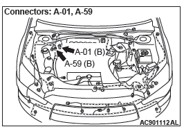
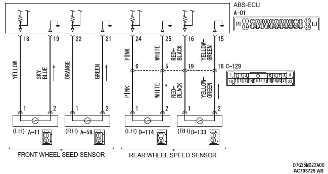
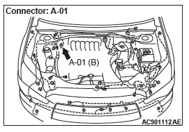
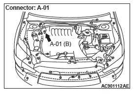
STEP 5. Connector check: A-01 ABS-ECU connector, A-11 front wheel speed sensor <LH> connector
Q: Is the check result normal?
YES : Go to Step 6.
NO : Repair the defective connector. Then go to Step 13.
STEP 6. Wiring harness check between A-01 ABS-ECU connector terminal No.18 and A-11 front wheel speed sensor <LH> connector terminal No.1, and between A-01 ABS-ECU connector terminal No.19 and A-11 front wheel speed sensor <LH> connector terminal No.2.
Q: Is the check result normal?
YES : Go to Step 7.
NO : Repair the wiring harness. Then go to Step 13.
STEP 7. Check wheel speed sensor <FL> installation Check how the wheel speed sensor <FL> is installed (Disconnection of wheel speed sensor <FL>, loose mounting bolt, etc.).
Q: Is the check result normal?
YES : Go to Step 8.
NO : Reinstall the wheel speed sensor <FL>. Then go to Step 8.
STEP 8. Check for wheel speed sensor <FL> output current
Q: Is the check result normal?
YES : Go to Step 9.
NO : Replace the wheel speed sensor <FL>. Then go to Step 12.
STEP 9. Check for wheel bearing looseness
NOTE:
- Loose wheel bearing may increase the gap between the wheel speed sensor <FL> and the wheel speed detection magnet encoder.
- Check the wheel bearing <FL> for looseness (Refer to GROUP 26 − Wheel Bearing Play Check).
Q: Is the check result normal?
YES : Go to Step 10.
NO : Replace the wheel bearing <FL> (Refer to GROUP 26 − Front Axle Hub Assembly). Then go to Step 13.
STEP 10. Check wheel speed detection encoder
Check the encoder for adhesion of foreign materials or deformation.
Q: Is the check result normal?
YES : Go to Step 11.
NO (Adhesion of foreign materials) : Remove the foreign materials and clean the encoder so as not to disturb the magnetization pattern on it while taking care of the magnet, magnetic substance, and magnetic attraction. Then go to Step 13.
NO (Deformation) : Replace the wheel bearing <FL> (Refer to GROUP 26 − Front Axle Hub Assembly). Then go to Step 13.
STEP 11. Check whether the DTC is reset.
- Erase the DTC.
- Drive the vehicle at 12mph (20 km/h) or higher.
NOTE: The ABS warning light does not turn OFF in some cases unless the vehicle runs at 12mph (20 km/h) or higher.
Q: Is DTC C1046 set?
YES : Replace the wheel speed sensor <FL>. Then go to Step 12.
NO : Intermittent malfunction (Refer to GROUP 00 − How to Use Troubleshooting/How to Cope with Intermittent Malfunctions).
STEP 12. Check whether the DTC is reset.
- Erase the DTC.
- Drive the vehicle at 12mph (20 km/h) or higher.
NOTE: The ABS warning light does not turn OFF in some cases unless the vehicle runs at 12mph (20 km/h) or higher.
Q: Is DTC C1046 set?
YES : Replace the hydraulic unit (integrated with ABS-ECU). Then go to Step 13.
NO : The procedure is complete.
STEP 13. Check whether the DTC is reset.
- Erase the DTC.
- Drive the vehicle at 12mph (20 km/h) or higher.
NOTE: The ABS warning light does not turn OFF in some cases unless the vehicle runs at 12mph (20 km/h) or higher.
Q: Is DTC C1046 set?
YES : Return to Step 1.
NO : The procedure is complete.
DTC C1047: FR wheel speed sensor control phase time exceeded
Wheel Speed Sensor Circuit
CAUTION If there is any problem in the CAN bus lines, an incorrect DTC may be set. Prior to this diagnosis, diagnose the CAN bus lines (Refer to GROUP 54C − CAN Bus Line Diagnostic Flow).
CIRCUIT OPERATION
- The wheel speed sensor is a type of pulse generator. It consists of encoders (a plate on which north and south pole sides of the magnets are arranged alternately) for detecting the wheel speed which rotates at the same speed of the wheels and wheel speed sensors. This sensor outputs frequency pulse signals in proportion to the wheel speed.
- The pulse signals, which the wheel speed sensor creates, are sent to ABS-ECU. ABS-ECU uses the frequency of the pulse signals to determine the wheel speed.
DTC SET CONDITIONS
This DTC is set if any malfunction below is found:
- When the brake fluid pressure is decreased for a long time.
- When the brake fluid pressure is held for a long time.
PROBABLE CAUSES
- Damaged wiring harness and connectors
- External noise interference
- Malfunction of wheel speed sensor
- ABS-ECU malfunction
- Excessive gap between the wheel speed sensor and the wheel speed detection encoder
- Adhesion of foreign materials on the wheel speed sensor
- Adhesion of foreign materials on the wheel speed detection encoder
- Wheel bearing malfunction
- Improper installation of the wheel speed sensor
- Deformation of the wheel speed detection encoder
- Disturbance of magnetization pattern for wheel speed detection encoder
- Missing teeth of the wheel speed detection encoder
DIAGNOSIS
Required Special Tools:
- MB991958: Scan Tool (M.U.T.-III Sub Assembly)
- MB991824: Vehicle Communication Interface (V.C.I.)
- MB991827: M.U.T.-III USB Cable
- MB991910: M.U.T.-III Main Harness A
STEP 1. Using scan tool MB991958, diagnose the CAN bus lines.
Use scan tool to diagnose the CAN bus lines.
Q: Is the check result normal?
YES : Go to Step 3.
NO : Repair the CAN bus lines (Refer to GROUP 54C − CAN Bus Diagnostics Table). On completion, go to Step 2.
STEP 2. DTC recheck after resetting CAN bus lines
Q: Is DTC C1047 set?
YES : Go to Step 3.
NO : The procedure is complete.
STEP 3. Using scan tool MB991958, check the DTC
Check that the DTCs C1015, C101C, C101F, or C1042 are also set.
Q: Are DTC C1015, C101C, C101F, or C1042 also set?
YES : Carry out the diagnosis for the relevant DTCs.
NO : Go to Step 4.
STEP 4. Using scan tool MB991958, check the data list
Check the following data list.
- Item No.02: FR wheel speed sensor
Q: Is the check result normal?
YES : Go to Step 11.
NO : Go to Step 5.
STEP 5. Connector check: A-01 ABS-ECU connector, A-59 front wheel speed sensor <RH> connector
Q: Is the check result normal?
YES : Go to Step 6.
NO : Repair the defective connector. Then go to Step 13.
STEP 6. Wiring harness check between A-01 ABS-ECU connector terminal No.22 and A-59 front wheel speed sensor <RH> connector terminal No.1, and between A-01 ABS-ECU connector terminal No.21 and A-59 front wheel speed sensor <RH> connector terminal No.2.
Q: Is the check result normal?
YES : Go to Step 7.
NO : Repair the wiring harness. Then go to Step 13.
STEP 7. Check wheel speed sensor <FR> installation
Check how the wheel speed sensor <FR> is installed (Disconnection of wheel speed sensor <FR>, loose mounting bolt, etc.).
Q: Is the check result normal?
YES : Go to Step 8.
NO : Reinstall the wheel speed sensor <FR>. Then go to Step 8.
STEP 8. Check for wheel speed sensor <FR> output current
Q: Is the check result normal?
YES : Go to Step 9.
NO : Replace the wheel speed sensor <FR>. Then go to Step 12.
STEP 9. Check for wheel bearing looseness
NOTE:
- Loose wheel bearing may increase the gap between the wheel speed sensor <FR> and the wheel speed detection magnet encoder.
- Check the wheel bearing <FR> for looseness (Refer to GROUP 26 − Wheel Bearing Play Check).
Q: Is the check result normal?
YES : Go to Step 10.
NO : Replace the wheel bearing <FR> (Refer to GROUP 26 − Front Axle Hub Assembly). Then go to Step 13.
STEP 10. Check wheel speed detection encoder
Check the encoder for adhesion of foreign materials or deformation.
Q: Is the check result normal?
YES : Go to Step 11.
NO (Adhesion of foreign materials) : Remove the foreign materials and clean the encoder so as not to disturb the magnetization pattern on it while taking care of the magnet, magnetic substance, and magnetic attraction. Then go to Step 13.
NO (Deformation) : Replace the wheel bearing <FR> (Refer to GROUP 26 − Front Axle Hub Assembly). Then go to Step 13.
STEP 11. Check whether the DTC is reset.
- Erase the DTC.
- Drive the vehicle at 12mph (20 km/h) or higher.
NOTE: The ABS warning light does not turn OFF in some cases unless the vehicle runs at 12mph (20 km/h) or higher.
Q: Is DTC C1047 set?
YES : Replace the wheel speed sensor <FR>. Then go to Step 12.
NO : Intermittent malfunction (Refer to GROUP 00 − How to Use Troubleshooting/How to Cope with Intermittent Malfunctions).
STEP 12. Check whether the DTC is reset.
- Erase the DTC.
- Drive the vehicle at 12mph (20 km/h) or higher.
NOTE: The ABS warning light does not turn OFF in some cases unless the vehicle runs at 12mph (20 km/h) or higher.
Q: Is DTC C1047 set?
YES : Replace the hydraulic unit (integrated with ABS-ECU). Then go to Step 13.
NO : The procedure is complete.
STEP 13. Check whether the DTC is reset.
- Erase the DTC.
- Drive the vehicle at 12mph (20 km/h) or higher.
NOTE: The ABS warning light does not turn OFF in some cases unless the vehicle runs at 12mph (20 km/h) or higher.
Q: Is DTC C1047 set?
YES : Return to Step 1.
NO : The procedure is complete.
DTC C1048: RL wheel speed sensor control phase time exceeded
Wheel Speed Sensor Circuit
CAUTION If there is any problem in the CAN bus lines, an incorrect DTC may be set. Prior to this diagnosis, diagnose the CAN bus lines (Refer to GROUP 54C − CAN Bus Line Diagnostic Flow).
CIRCUIT OPERATION
- The wheel speed sensor is a type of pulse generator. It consists of encoders (a plate on which north and south pole sides of the magnets are arranged alternately) for detecting the wheel speed which rotates at the same speed of the wheels and wheel speed sensors. This sensor outputs frequency pulse signals in proportion to the wheel speed.
- The pulse signals, which the wheel speed sensor creates, are sent to ABS-ECU. ABS-ECU uses the frequency of the pulse signals to determine the wheel speed.
DTC SET CONDITIONS
This DTC is set if any malfunction below is found:
- When the brake fluid pressure is decreased for a long time.
- When the brake fluid pressure is held for a long time.
PROBABLE CAUSES
- Damaged wiring harness and connectors
- External noise interference
- Malfunction of wheel speed sensor
- ABS-ECU malfunction
- Excessive gap between the wheel speed sensor and the magnetic encoder for wheel speed detection
- Adhesion of foreign materials on the wheel speed sensor
- Adhesion of foreign materials on the magnetic encoder for wheel speed detection
- Wheel bearing malfunction
- Improper installation of the wheel speed sensor
- Deformation of the magnetic encoder for wheel speed detection
- Disturbance of magnetization pattern for magnetic encoder for wheel speed detection
- Missing teeth of the magnetic encoder for wheel speed detection
DIAGNOSIS
Required Special Tools:
- MB991958: Scan Tool (M.U.T.-III Sub Assembly)
- MB991816: Vehicle Communication Interface (V.C.I.)
- MB991827: M.U.T.-III USB Cable
- MB991910: M.U.T.-III Main Harness A
STEP 1. Using scan tool MB991958, diagnose the CAN bus lines.
Use scan tool to diagnose the CAN bus lines.
Q: Is the check result normal?
YES : Go to Step 3.
NO : Repair the CAN bus lines (Refer to GROUP 54C − CAN Bus Diagnostics Table). On completion, go to Step 2.
STEP 2. DTC recheck after resetting CAN bus lines
Q: Is DTC C1048 set?
YES : Go to Step 3.
NO : The procedure is complete.
STEP 3. Using scan tool MB991958, check the DTC
Check that the DTCs C1020, C1027, C102A, or C1043 are also set.
Q: Are DTC C1020, C1027, C102A, or C1043 also set?
YES : Carry out the diagnosis for the relevant DTCs.
NO : Go to Step 4.
STEP 4. Using scan tool MB991958, check the data list
Check the following data list).
- Item No.03: RL wheel speed sensor
Q: Is the check result normal?
YES : Go to Step 11.
NO : Go to Step 5.
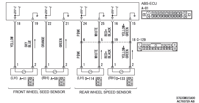
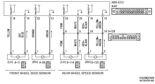
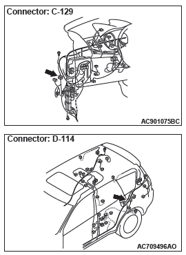
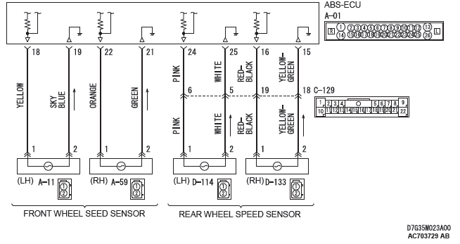
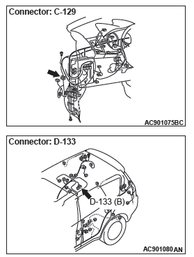
STEP 5. Connector check: A-01 ABS-ECU connector, C-129 intermediate connector, D-114 rear wheel speed sensor <LH> connector
Q: Is the check result normal?
YES : Go to Step 6.
NO : Repair the defective connector. Then go to Step 13.
STEP 6. Wiring harness check between A-01 ABS-ECU connector terminal No.24 and D-114 rear wheel speed sensor <LH> connector terminal No.1, and between A-01 ABS-ECU connector terminal No.25 and D-114 rear wheel speed sensor <LH> connector terminal No.2.
Q: Is the check result normal?
YES : Go to Step 7.
NO : Repair the wiring harness. Then go to Step 13.
STEP 7. Check for wheel speed sensor <RL> installation
Check how the wheel speed sensor <RL> is installed (Disconnection of wheel speed sensor <RL>, loose mounting bolt, etc.).
Q: Is the check result normal?
YES : Go to Step 8.
NO : Reinstall the wheel speed sensor <RL> correctly. Then go to Step 8.
STEP 8. Check for wheel speed sensor <RL> output current
Q: Is the check result normal?
YES : Go to Step 9.
NO : Replace the wheel speed sensor <RL>. Then go to Step 12.
STEP 9. Check for wheel bearing looseness
NOTE:
- Loose wheel bearing may increase the gap between the wheel speed sensor<RL> and the wheel speed detection magnet encoder.
- Check the wheel bearing <RL> for looseness (Refer to GROUP 27A − On-vehicle Service).
Q: Is the check result normal?
YES : Go to Step 10.
NO : Replace the rear wheel hub assembly <RL> (Refer to GROUP 27A − Rear Axle Hub Assembly).
Then go to Step 13.
STEP 10. Check of wheel speed detection encoder
Check the encoder for adhesion of foreign materials or deformation.
Q: Is the check result normal?
YES : Go to Step 11.
NO (Adhesion of foreign materials) : Remove the foreign materials and clean the encoder so as not to disturb the magnetization pattern on it while taking care of the magnet, magnetic substance, and magnetic attraction. Then go to Step 13.
NO (Deformation) : Replace the rear wheel hub assembly <RL> (Refer to GROUP 27A − Rear Axle Hub Assembly). Then go to Step 13.
STEP 11. Check whether the DTC is reset.
- Erase the DTC.
- Drive the vehicle at 12mph (20 km/h) or higher.
NOTE: The ABS warning light does not turn OFF in some cases unless the vehicle runs at 12mph (20 km/h) or higher.
Q: Is DTC C1048 set?
YES : Replace the wheel speed sensor <RL>. Then go to Step 12.
NO : Intermittent malfunction (Refer to GROUP 00 − How to Use Troubleshooting/How to Cope with Intermittent Malfunctions).
STEP 12. Check whether the DTC is reset.
- Erase the DTC.
- Drive the vehicle at 12mph (20 km/h) or higher.
NOTE: The ABS warning light does not turn OFF in some cases unless the vehicle runs at 12mph (20 km/h) or higher.
Q: Is DTC C1048 set?
YES : Replace the hydraulic unit (integrated with ABS-ECU). Then go to Step 13.
NO : The procedure is complete.
STEP 13. Check whether the DTC is reset.
- Erase the DTC.
- Drive the vehicle at 12mph (20 km/h) or higher.
NOTE: The ABS warning light does not turn OFF in some cases unless the vehicle runs at 12mph (20 km/h) or higher.
Q: Is DTC C1048 set?
YES : Return to Step 1.
NO : The procedure is complete.
DTC C1049: RR wheel speed sensor control phase time exceeded
Wheel Speed Sensor Circuit
CAUTION If there is any problem in the CAN bus lines, an incorrect DTC may be set. Prior to this diagnosis, diagnose the CAN bus lines (Refer to GROUP 54C − CAN Bus Line Diagnostic Flow).
CIRCUIT OPERATION
- The wheel speed sensor is a type of pulse generator. It consists of encoders (a plate on which north and south pole sides of the magnets are arranged alternately) for detecting the wheel speed which rotates at the same speed of the wheels and wheel speed sensors. This sensor outputs frequency pulse signals in proportion to the wheel speed.
- The pulse signals, which the wheel speed sensor creates, are sent to ABS-ECU. ABS-ECU uses the frequency of the pulse signals to determine the wheel speed.
DTC SET CONDITIONS
This DTC is set if any malfunction below is found:
- When the brake fluid pressure is decreased for a long time.
- When the brake fluid pressure is held for a long time.
PROBABLE CAUSES
- Damaged wiring harness and connectors
- External noise interference
- Malfunction of wheel speed sensor
- ABS-ECU malfunction
- Excessive gap between the wheel speed sensor and the magnetic encoder for wheel speed detection
- Adhesion of foreign materials on the wheel speed sensor
- Adhesion of foreign materials on the magnetic encoder for wheel speed detection
- Wheel bearing malfunction
- Improper installation of the wheel speed sensor
- Deformation of the magnetic encoder for wheel speed detection
- Disturbance of magnetization pattern for magnetic encoder for wheel speed detection
- Missing teeth of the magnetic encoder for wheel speed detection
DIAGNOSIS
Required Special Tools:
- MB991958: Scan Tool (M.U.T.-III Sub Assembly)
- MB991816: Vehicle Communication Interface (V.C.I.)
- MB991827: M.U.T.-III USB Cable
- MB991910: M.U.T.-III Main Harness A
STEP 1. Using scan tool MB991958, diagnose the CAN bus lines.
Use scan tool to diagnose the CAN bus lines.
Q: Is the check result normal?
YES : Go to Step 3.
NO : Repair the CAN bus lines (Refer to GROUP 54C − CAN Bus Diagnostics Table). On completion, go to Step 2.
STEP 2. DTC recheck after resetting CAN bus lines
Q: Is DTC C1049 set?
YES : Go to Step 3.
NO : The procedure is complete.
STEP 3. Using scan tool MB991958, check the DTC
Check that the DTCs C102B, C1032, C1035, or C1044 are also set.
Q: Are DTC C102B, C1032, C1035, or C1044 also set?
YES : Carry out the diagnosis for the relevant DTCs.
NO : Go to Step 4.
STEP 4. Using scan tool MB991958, check the data list
Check the following data list.
- Item No.04: RR wheel speed sensor
Q: Is the check result normal?
YES : Go to Step 11.
NO : Go to Step 5.
STEP 5. Connector check: A-01 ABS-ECU connector, C-129 intermediate connector, D-133 rear wheel speed sensor <RH> connector
Q: Is the check result normal?
YES : Go to Step 6.
NO : Repair the defective connector. Then go to Step 13.
STEP 6. Wiring harness check between A-01 ABS-ECU connector terminal No.16 and D-133 rear wheel speed sensor <RH> connector terminal No.1, and between A-01 ABS-ECU connector terminal No.15 and D-133 rear wheel speed sensor <RH> connector terminal No.2.
Q: Is the check result normal?
YES : Go to Step 7.
NO : Repair the wiring harness. Then go to Step 13.
STEP 7. Check for wheel speed sensor <RR> installation
Check how the wheel speed sensor <RR> is installed (Disconnection of wheel speed sensor <RR>, loose mounting bolt, etc.).
Q: Is the check result normal?
YES : Go to Step 8.
NO : Reinstall the wheel speed sensor <RR> correctly. Then go to Step 8.
STEP 8. Check for wheel speed sensor <RR> output current
Q: Is the check result normal?
YES : Go to Step 9.
NO : Replace the wheel speed sensor <RR>. Then go to Step 12.
STEP 9. Check for wheel bearing looseness
NOTE:
- Loose wheel bearing may increase the gap between the wheel speed sensor and the wheel speed detection magnet encoder.
- Check the wheel bearing <RR> for looseness (Refer to GROUP 27A − On-vehicle Service).
Q: Is the check result normal?
YES : Go to Step 10.
NO : Replace the rear wheel hub assembly (Refer to GROUP 27A − Rear Axle Hub Assembly).
Then go to Step 13.
STEP 10. Check of wheel speed detection encoder
Check the encoder for adhesion of foreign materials or deformation.
Q: Is the check result normal?
YES : Go to Step 11.
NO (Adhesion of foreign materials) : Remove the foreign materials and clean the encoder so as not to disturb the magnetization pattern on it while taking care of the magnet, magnetic substance, and magnetic attraction. Then go to Step 13.
NO (Deformation) : Replace the rear wheel hub assembly <RR> (Refer to GROUP 27A − Rear Axle Hub Assembly). Then go to Step 13.
STEP 11. Check whether the DTC is reset.
- Erase the DTC.
- Drive the vehicle at 12mph (20 km/h) or higher.
NOTE: The ABS warning light does not turn OFF in some cases unless the vehicle runs at 12mph (20 km/h) or higher.
Q: Is DTC C1049 set?
YES : Replace the wheel speed sensor <RR>. Then go to Step 12.
NO : Intermittent malfunction (Refer to GROUP 00 − How to Use Troubleshooting/How to Cope with Intermittent Malfunctions).
STEP 12. Check whether the DTC is reset.
- Erase the DTC.
- Drive the vehicle at 12mph (20 km/h) or higher.
NOTE: The ABS warning light does not turn OFF in some cases unless the vehicle runs at 12mph (20 km/h) or higher.
Q: Is DTC C1049 set?
YES : Replace the hydraulic unit (integrated with ABS-ECU). Then go to Step 13.
NO : The procedure is complete.
STEP 13. Check whether the DTC is reset.
- Erase the DTC.
- Drive the vehicle at 12mph (20 km/h) or higher.
NOTE: The ABS warning light does not turn OFF in some cases unless the vehicle runs at 12mph (20 km/h) or higher.
Q: Is DTC C1049 set?
YES : Return to Step 1.
NO : The procedure is complete.
DTC C104B: Abnormality in FL wheel inlet valve system
DTC C104F: Abnormality in FR wheel inlet valve system
DTC C1053: Abnormality in RL wheel inlet valve system
DTC C1057: Abnormality in RR wheel inlet valve system
DTC C105F: Abnormality in FL wheel outlet valve system
DTC C1063: Abnormality in FR wheel outlet valve system
DTC C1067: Abnormality in RL wheel outlet valve system
DTC C105B: Abnormality in RR wheel outlet valve system
CAUTION If there is any problem in the CAN bus lines, an incorrect DTC may be set. Prior to this diagnosis, diagnose the CAN bus lines (Refer to GROUP 54C − CAN Bus Line Diagnostic Flow).
CIRCUIT OPERATION
- ABS-ECU contains the power supply circuit (terminal No.26) for the solenoid valve. The solenoid valve is energized by the valve relay, which is incorporated in ABS-ECU.
- The valve relay, which is incorporated in ABS-ECU, is always energizing the solenoid valve unless the initial check is in progress when the ignition switch is turned on, and the recurrent system check is in progress.
- ABS-ECU activates the solenoid valve by turning on its driving transistor.
DTC SET CONDITIONS
These DTCs will be set under the conditions below:
- The solenoid valve is not energized even after ABS-ECU has turned on the driving transistor (Open circuit is present in the power supply circuit to the ABS-ECU solenoid valve, or the valve relay has failed).
- The solenoid valve is not activated even after ABS-ECU has turned on the driving transistor (Open circuit is present in the solenoid valve circuit in ABS-ECU, or the valve relay has failed).
- After ABS-ECU has turned off the valve relay, the solenoid valve still remains energized (short in the solenoid valve circuit).
- When a solenoid valve failure is detected
PROBABLE CAUSES
- ABS-ECU malfunction
DIAGNOSIS
Required Special Tools:
- MB991958: Scan Tool (M.U.T.-III Sub Assembly)
- MB991824: Vehicle Communication Interface (V.C.I.)
- MB991827: M.U.T.-III USB Cable
- MB991910: M.U.T.-III Main Harness A
STEP 1. Using scan tool MB991958, diagnose the CAN bus line.
Use scan tool MB991958 to diagnose the CAN bus lines.
Q: Is the check result normal?
YES : Go to Step 3.
NO : Repair the CAN bus lines (Refer to GROUP 54C − CAN Bus Diagnostics Table).On completion, go to Step 2.
STEP 2. DTC recheck after resetting CAN bus lines
Q: Is the relevant DTC set?
YES : Go to Step 3.
NO : The procedure is complete.
STEP 3. Check whether the DTC is reset.
Erase the DTC.
Q: Is the relevant DTC set?
YES : Replace the hydraulic unit (integrated with ABS-ECU). Then go to Step 4.
NO : Intermittent malfunction (Refer to GROUP 00 − How to Use Troubleshooting/How to Cope with Intermittent Malfunctions).
STEP 4. Check whether the DTC is reset.
Erase the DTC.
Q: Is the relevant DTC set?
YES : Return to Step 1.
NO : The procedure is complete.
READ NEXT:
 DTC C2104, C1073, C2116, C1000, C2200, C2100, C2101, C1395, C2203,
C1608, U0001, U0100, U0141, U1415, U1417
DTC C2104, C1073, C2116, C1000, C2200, C2100, C2101, C1395, C2203,
C1608, U0001, U0100, U0141, U1415, U1417
DTC C2104 Faulty valve power supply circuit
Power Supply Circuit
CAUTION
If there is any problem in the CAN bus lines, an incorrect
DTC may be set. Prior to this diagnosis, diagnose the CAN
bus line
Symptom Chart, Symptom Procedures
SYMPTOM CHART
CAUTION
ABS may operate in the following conditions without hard braking:
Slippery road surface,
high-speed turn, and bumpy road surface. When asking the customers, confirm
that t
On-vehicle Service
WHEEL SPEED SENSOR OUTPUT CURRENT
MEASUREMENT
Required Special Tools:
MB991709: Wiring harness set
The relevant wheel, on which the wheel speed sensor is fitted,
should be free to run.
1. Remove t
SEE MORE:
Forward Clutch
DISASSEMBLY AND ASSEMBLY
Disassembly steps
Snap ring
Internal gear
Snap ring
Snap ring
Seal ring (small)
Seal ring (big)
Input shaft
Forward clutch sub-assembly
DISASSEMBLY SERVICE POINT
SNAP RING REMOVAL
Using a flat blade screwdriver etc., remove the snap ring from
the forward clutch dr
Fuses
Fuse block location
To prevent damage to the electrical system due to shortcircuiting or overloading,
each individual circuit is provided with a fuse.
There are fuse blocks in the passenger compartment and in the engine compartment.
Passenger compartment (LHD vehicles)
The fuse block in the pa
