Mitsubishi Outlander: On-vehicle Service
BRAKE PEDAL INSPECTION
CAUTION Do not apply grease or lubricant to the switch and the switch installation section to avoid malfunction of the switch. In addition, do not use gloves which have grease on them.
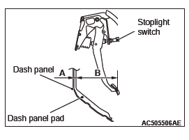
BRAKE PEDAL HEIGHT CHECK
1. Turn up the floor carpet under the brake pedal.
2. Remove the stoplight switch.
3. Use a needle or similar tool to measure the dimension A in the figure (distance from the dash panel pad surface to the dash panel).
4. Measure the dimension B in the figure (distance from the pedal pad surface to the dash panel pad surface).
5. Make sure that the total of the dimensions A and B measured in Steps 2 and 3 (brake pedal height) is within the standard value.
Standard value (A+B): 221.8 − 227.8 mm (8.7 − 9.0 inch)
6. When the brake pedal height is not within the standard value, inspect the brake pedal in the following procedure.
- Remove the brake pedal assembly.
- Check the removed brake pedal assembly for distortion, and replace it when deformed.
- Install the brake pedal assembly.
NOTE: When installing, compress the dash panel pad.
- Measure the brake pedal height again, and make sure
that it is within the standard value (A+B).
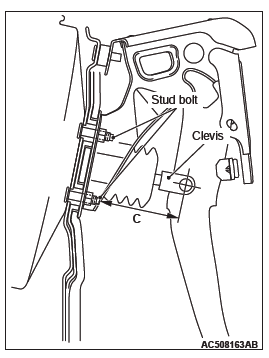
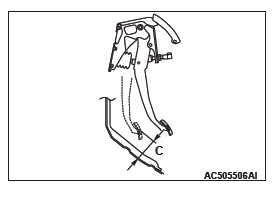
When the measured value is not within the standard value, measure the dimension C in the figure (distance from the stud bolt end to the clevis hole center), and make sure it is within the standard value (C).
Standard value (C): 75.8 − 80.2 mm (2.98 − 3.16 inch)
- When the measured value is not within the standard value (C), replace the brake booster.
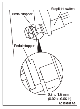
7. After checking the brake pedal height, install the stoplight switch in the following procedure:
- Screw in the stoplight switch until its thread contacts the pedal stopper, then turn the switch approximately one eighth of a clockwise turn to fix it. While doing this, pull and hold the brake pedal by hand.
- Check that the clearance between the stoplight switch and the pedal stopper is as shown in the figure.
CAUTION Make sure that the stoplight is not illuminated when the brake pedal is not depressed.
- Connect the stoplight switch connector.
8. Check the key interlock mechanism and the shift lock mechanism.
9. Recover the floor carpet under the brake pedal.
BRAKE PEDAL PLAY CHECK AND ADJUSTMENT
1. With the engine stopped, depress the brake pedal 2 or 3 times to relieve the vacuum in the brake booster. Then, press the brake pedal with your finger and check if the pedal stroke until the pedal becomes heavy (play) is within the standard value.
Standard value (B): 3 − 8 mm (0.12 − 0.31 inch)
2. When the brake pedal play is not within the standard value, check the brake pedal-to-clevis pin looseness, clevis pin-to-booster operating rod looseness, brake pedal height, and stoplight switch position, and adjust or replace as necessary.
BRAKE PEDAL-TO-FLOOR PANEL CLEARANCE CHECK AND ADJUSTMENT
1. Turn up the floor carpet under the brake pedal.
2. Start the engine and depress the brake pedal with approximately 500 N (112 pounds), and measure clearance between the brake pedal and the floor panel.
Standard value (C): 80 mm (3.15 inch) or more
3. When the clearance is not within the standard value, check for the air in the brake line and thickness of the disc brake pad, and correct or replace as necessary.
4. Recover the floor carpet under the brake pedal.
BRAKE BOOSTER OPERATION CHECK
INSPECTION WITHOUT USING TESTER
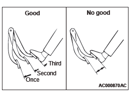
1. Carry out the simplified brake booster operation check in the following procedure:
- Run the engine for 1 to 2 minutes, and then stop.
Depress the brake pedal with normal depression force.
The result is judged as "Good" when the pedal stroke is great at the first depression, and becomes smaller as you repeat depressing the pedal. If the pedal stroke does not change, the result is judged as "No Good".
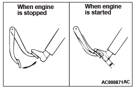
- With the engine stopped, depress the brake pedal several times. Keep the brake pedal depressed and start the engine. At this time, when the pedal moves down slightly, the result is judged as "Good". The result is judged as "No Good" if the pedal does not moves down.
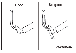
- With the engine running, depress the brake pedal. Stop the engine in this condition. The result is judged as "Good" when the pedal height does not change for approximately 30 seconds. The result is judged as "No Good" if the pedal moves up.
2. The brake booster is judged as normal when the results of all the above checks are "Good". When one or more of the above check results are "No Good", then the check valve, vacuum hose, or brake booster is suspected faulty.
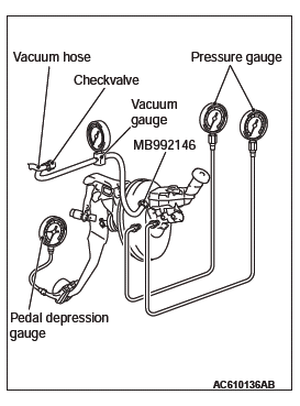
INSPECTION USING SIMPLIFIED TESTER
1. Before starting this inspection, remove the brake booster check valve from the vehicle and check its operation.
2. After checking, install the check valve to the vacuum hose and connect it to the vacuum gauge. Install the booster test adapter (Special tool: MB992146) to the brake booster and connect it to the vacuum gauge. Connect the pressure gauge and pedal depression gauge as shown in the figure.
Bleed the pressure gauge and then perform the following tests:
- Airtightness test with no load
Start the engine, and stop it when the vacuum gauge indicator has reached approximately −67 kPa (−9.7 psi).The result is judged as "Good" when the drop of the vacuum approximately 15 seconds after the engine was stopped is within −3.3 kPa (−0.5 psi).
- Airtightness test with load
Start the engine and depress the brake pedal with 200 N.Stop the engine when the vacuum gauge indicator reached approximately −67 kPa (−9.7 psi). The result is judged as "Good" when the drop of the vacuum approximately 15 seconds after the engine was stopped is within −3.3 kPa (−0.5 psi).
When one or more of the above check results are judged as "No Good", the vacuum hose or brake booster is suspected faulty.
- Brake booster characteristics test
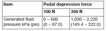
Perform this test after the above (1) and (2) were performed.- Non-servo effecnt test
With the engine stopped, make sure that the vacuum gauge reading is 0 kPa (0 psi). Depress the brake pedal with 100 N and 300 N, and measure the fluid pressure generated.
- Non-servo effecnt test
Standard value:
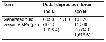
- Servo effect test
Start the engine. Depress the brake pedal with 100 N and 300 N when the vacuum gauge indicator reached approximately −67 kPa (−9.7 psi), and measure the fluid pressure generated.
Standard value:
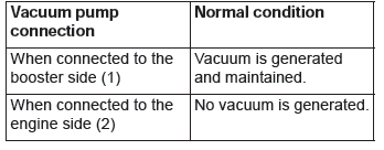
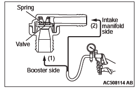
CHECK VALVE OPERATION
1. Remove the check valve.
CAUTION Replace the check valve when it is faulty.
2. Using a vacuum pump, check operation of the check valve.
BLEEDING
CAUTION
Be sure to use the specified brand and type of brake fluid.
Avoid mixing with other type of brake fluid.
Brake fluid: DOT3 or DOT4
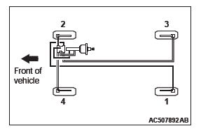
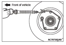
BLEEDING OF BRAKE PIPELINE
Perform the bleeding in the order shown in the figure.
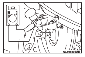
BRAKE FLUID LEVEL SWITCH CHECK
The brake fluid level switch is normal when the following conditions are met: When the brake fluid level is above "MIN", continuity is detected; and when the level is below "MIN", no continuity is detected.
BRAKE PAD CHECK
CAUTION
If there is a significant difference in thickness between the brake pads at right and left, check the sliding area and the runout of the brake disk.
1. Visually check the thickness of brake pad from the inspection hole of the caliper body.
Standard value: 10.0 mm (0.39 inch)
Limit: 2.0 mm (0.08 inch)
2. If the brake pad thickness is less than the limit value, replace the brake pad.
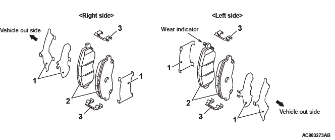
BRAKE PAD REPLACEMENT
<FRONT>
CAUTION When replacing, replace both brake pads (right and left) as a set.
1. Remove the parts indicated in the figure, swivel the caliper body upward and retain it with a wire or similar tool.
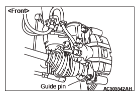
2. Remove the following parts from the caliper body.
- Shim
- Brake pad assembly
- Clip
CAUTION Keep grease or other soiling off the pad and brake disk friction surfaces.
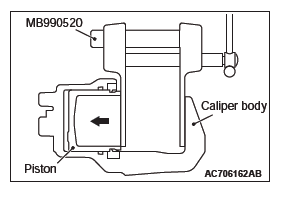
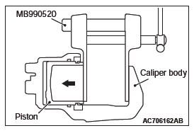
3. Clean the piston part, and press the piston into the cylinder using the special tool piston expander (MB990520).
4. Assemble the shim, brake pad assembly and clip to the caliper support, and tighten the guide pin to the specified torque.
Tightening torque: 44 +- 5 N*m (32 +- 4 ft-lb)
NOTE: Install the brake pad assembly (with wear indicator) to the inner side of the brake disk, making sure that the wear indicator is located on the top.
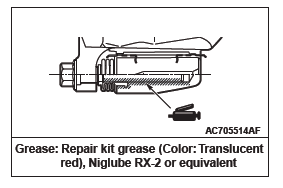
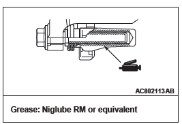
LUBRICATION POINT
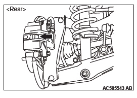
<REAR>
CAUTION When replacing, replace both brake pads (right and left) as a set.
1. Remove the parts indicated in the figure, swivel the caliper body upward and retain it with a wire or similar tool.
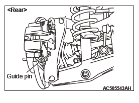
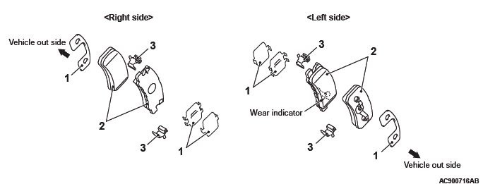
2. Remove the following parts from the caliper body.
- Shim
- Brake pad assembly
- Clip
CAUTION Keep grease or other soiling off the pad and brake disk friction surfaces.
3. Clean the piston part, and press the piston into the cylinder using the special tool piston expander (MB990520).
4. Assemble the shim, brake pad assembly and clip to the caliper support, and tighten the guide pin to the specified torque.
Tightening torque: 44 +- 5 N*m (32 +- 4 ft-lb)
NOTE: Install the brake pad assembly (with wear indicator) to the inner side of the brake disk, making sure that the wear indicator is located on the bottom.
LUBRICATION POINT BRAKE DISC CHECK

CAUTION Disc brakes must be kept within the allowable service values in order to maintain normal brake operation.
Before turning the brake disc, the following conditions should be checked.
BRAKE DISC THICKNESS CHECK
1. Remove contaminants or corrosion from the brake disc surface.
2. Use a micrometer to measure the brake disc thickness at minimum eight points which are 10 mm (0.39 inch) inward from its circumference.
Standard value:
26.0 mm (1.02 inch) <Front>
10.0 mm (0.39 inch) <Rear>
Limit:
24.4 mm (0.96 inch) <Front>
8.4 mm (0.33 inch) <Rear>
3. If the brake disc thickness is worn beyond the limit value at more than one point, replace the brake disc and check its run-out.
BRAKE DISC THICKNESS UNEVENNESS CHECK AND CORRECTION
1. Remove contaminants or corrosion from the brake disc surface.
2. Use a micrometer to measure the brake disc thickness at minimum eight points which are 10 mm (0.39 inch) inward from its circumference. Then record the measurements.
3. If the brake disc thickness unevenness (the difference between the maximum and minimum values measured above) is 0.015 mm (0.0006 inch) or less, it is within the standard value.
4. If the brake disc thickness unevenness exceeds the standard value, grind it according to the procedure below while it is mounted on the vehicle.
NOTE: If it is suspected that the brake disc thickness will become less than the limit value after the grinding, replace the brake disc and check its run-out.
- Check for wheel bearing looseness in the axial direction.
CAUTION
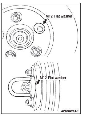
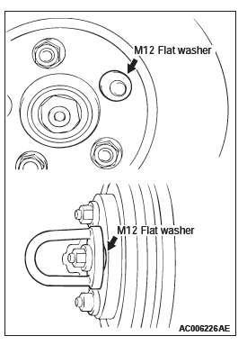
- Insert M12 plain washer and then install the adapter as shown before grinding. Failure to use the M12 plain washer will cause the brake disc to be deformed and ground incorrectly.
- To grind the brake disc, ensure that all the nuts (M12 X 1.5) are tightened evenly and in a diagonal sequence to the specified torque [100 N*m (74 ft-lb) ]. Failure to use all the nuts (M12×1.5), excessive or uneven tightening torque will cause the brake disc to deform or judder.
- Correct the brake disc uneven thickness by grinding it while in place on the vehicle.
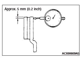
BRAKE DISC RUN-OUT CHECK AND CORRECTION
1. Check for wheel bearing looseness in the axial direction.
2. If the end play is within the limit value, secure the brake disc by tightening the nut (M12×1.5) evenly to the specified torque [100 N*m (74 ft-lb) ].If the end play still exceeds the limit value, replace the wheel bearing. Then secure the brake disc by tightening the nut (M12×1.5) evenly to the specified torque [100 N*m (74 ft-lb) ].
3. Place a dial gauge ca. 5 mm (0.2 inch) inward from the circumference of the brake disc to measure its run-out.
Limit:
0.06 mm (0.0024 inch) <Front>
0.08 mm (0.0032 inch) <Rear>
4. If the brake disc run-out exceeds the limit value, rephase the brake disc to the hub so that the minimum brake disc run-out is obtained.
CAUTION
- Insert M12 plain washer and then install the adapter as shown before grinding. Failure to use the M12 plain washer will cause the brake disc to be deformed and ground incorrectly.
- To grind the brake disc, ensure that all the nuts (M12 X 1.5) are tightened evenly and in a diagonal sequence to the specified torque [100 N*m (74 ft-lb) ]. Failure to use all the nuts (M12×1.5), excessive or uneven tightening torque will cause the brake disc to deform or judder.
5. If the brake disc run-out exceeds the limit value after rephasing, grind the disc while in place on the vehicle so that the brake disc run-out is within the limit value.
NOTE: If it is suspected that the brake disc thickness will be below the limit value, replace the brake disc. Then rephase the brake disc so that the minimum brake disc run-out is obtained, or grind the disc while in place on the vehicle so that its run-out is below the limit value.
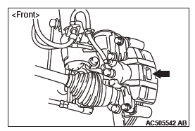
BRAKE DRAG FORCE CHECK
1. Remove the brake pad, shim and clip.
2. Using a spring scale, measure the hub sliding torque in the forward direction with the brake pad, shim and clip removed.
3. Install the brake pad, shim and clip.
4. Start the engine, and depress the brake pedal lightly two or three times. Then stop the engine. [Depressing force: approximately 50 − 100 N (11.2 − 22.5 pound) ]
5. Turn the brake disk 10 times in the forward direction.
6. Using a spring scale, measure the hub sliding torque in the forward direction with the brake pad, shim and clip installed.
7. Obtain the disk brake drag force (difference between measured values of item 2 and item 6).
Standard value: 68 N (15.3 pounds) or less
8. If the brake drag force exceeds the standard value, disassemble the brake caliper assembly to check for fouling/rust on the piston sliding section and piston seal deterioration, and confirm whether the guide pin and lock pin slide properly.
Brake Pedal
REMOVAL AND INSTALLATION
CAUTION
Do not apply grease or lubricant to the switch and the switch installation section to avoid malfunction of the switch. In addition, do not use gloves which have grease on them.
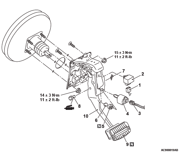
Removal steps
- Stoplight relay connector connection
- Stoplight relay
- Stoplight switch connector connection
- Stoplight switch
- Pedal clip
- Pedal stopper
- Snap pin
- Pin assembly
- Pedal pad
- Brake pedal assembly
REMOVAL SERVICE POINT
BRAKE PEDAL ASSEMBLY REMOVAL
From the engine compartment side, remove the brake pedal assembly while pulling the brake booster.
INSPECTION
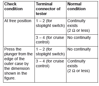
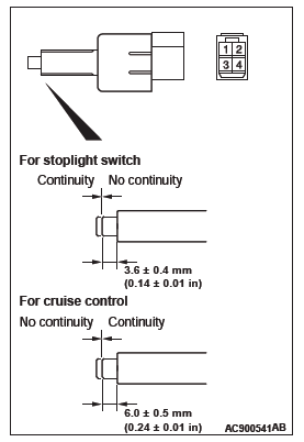
STOPLIGHT SWITCH CHECK
CAUTION Do not apply grease or lubricant to the switch and the switch installation section to avoid malfunction of the switch. In addition, do not use gloves which have grease on them.
Check for continuity between the terminals of the switch.
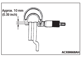
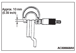
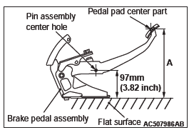
BRAKE PEDAL DISTORTION CHECK
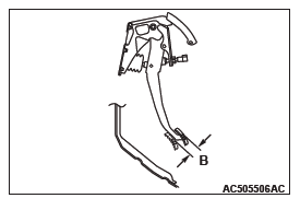
1. Place the brake pedal assembly on a level surface as shown in the figure, and set the distance from the centre of the pin assembly mounting hole to the level surface to 97 mm (3.82 inch). Make sure that the dimension A in the figure (distance from the pedal pad surface to the level surface) is within the standard value.
Standard value (A): 250 − 254 mm (9.8 − 10.0 inch)
2. When dimension A is not within the standard value, replace the brake pedal assembly.
Master Cylinder Assembly and Brake Booster Assembly
REMOVAL AND INSTALLATION
CAUTION Do not touch the push rod in the brake booster because it is already adjusted.
Pre-removal operation
- Brake Fluid Draining
- Bottom Cover Assembly (driver's seat) Removal
- Air Cleaner Body Removal
Post-installation operation
- Air Cleaner Body Installation
- Brake Fluid Refilling and Air Bleeding
- Bottom Cover Assembly (driver's seat) Installation
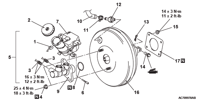
Master cylinder removal steps
- Brake fluid level switch connector connection
- Reservoir cap
- Brake pipe connection
- Bleeding of master cylinder assembly (only at installation)
- Master cylinder mounting nuts
- Reservoir assembly and master cylinder assembly
- Torx bolt
- Reservoir assembly
- O-ring
- Master cylinder assembly
Brake booster removal steps
- Brake fluid level switch connector connection
- Brake pipe connection
- Bleeding of master cylinder assembly (only at installation)
- Master cylinder mounting nuts
- Reservoir assembly and master cylinder assembly
- Vacuum hose connection
- Hose clip
- Check valve
- Snap pin
- Pin assembly
- Brake booster mounting nut
- Strut tower bar
- Brake booster assembly
- Seal
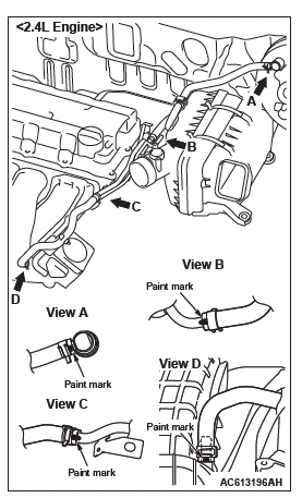
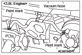
<VACUUM HOSE AND VACUUM PIPE>

Removal steps
- Vacuum hose
- Hose clip
- Vacuum hose <2.4L Engine>
- Hose clip <2.4L Engine>
- Emission vacuum hose connection <2.4L Engine>
- Vacuum pipe assembly <2.4L Engine>
- Clamp <3.0L Engine>
INSTALLATION SERVICE POINTS
VACUUM HOSE INSTALLATION
Align the mark as shown in the figure to assemble the vacuum hose.
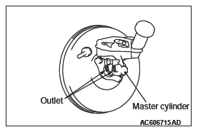
BLEEDING OF MASTER CYLINDER ASSEMBLY
When removed the master cylinder assembly, bleed the master cylinder in the following procedure to make bleeding of the brake pipeline easier (When no brake fluid is in the master cylinder).
1. Fill the brake fluid reservoir with the brake fluid.
2. Depress and hold the brake pedal.
3. Another operator closes the master cylinder outlets with his fingers.
4. In this condition, release the brake pedal.
5. Repeat Steps 2 to 4 for 3 or 4 times to fill the master cylinder with the brake fluid.
READ NEXT:
 Front Disc Brake Assembly
REMOVAL AND INSTALLATION
Pre-removal operation
Brake Fluid Draining
Post-installation operation
Brake Fluid Refilling and Air Bleeding
Brake Disk Runout Inspection/Correction
Removal steps
B
Rear Disc Brake Assembly
REMOVAL AND INSTALLATION <2.4L ENGINE: 5 PERSONS SEAT>
Pre-removal operation
Brake Fluid Draining
Post-installation operation
Brake Fluid Refilling and Air Bleeding
Brake Disk Runout Inspe
Anti-lock Braking System (ABS)
General Information
The 4ABS ensures directional skid and control during
hard braking.
This ABS uses a 4-sensor system that controls all
four wheels independently of each other.
EBD *1control can o
SEE MORE:
Vehicle care precautions
In order to maintain the value of your vehicle, it is necessary to perform regular
maintenance using the proper procedures.
Always maintain your vehicle in compliance with any environmental pollution control
regulations.
Carefully select the materials used for washing, etc., to be sure that th
DTC C100A, C1015, C1020, C102B, C1011, C101C, C1027, C1032, C1014,
C101F, C102A, C1035
DTC C100A: Abnormality in FL wheel speed sensor circuit
Wheel Speed Sensor Circuit
CAUTION
If there is any problem in the CAN bus lines, an incorrect
DTC may be set. Prior to this diagnosis, diagnose the CAN
bus lines.
CIRCUIT OPERATION
The wheel speed sensor is a type of pulse generator. It con
