Mitsubishi Outlander: Balancer Timing Chain, Balancer Shaft and Oil Pump Module
REMOVAL AND INSTALLATION
Pre-removal and Post-installation Operation
- Timing Chain Removal and Installation
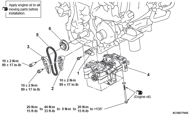
Removal steps
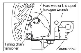
- Timing chain tensioner
- Balancer timing chain guide
- Balancer timing chain guide
- Balancer shaft and oil pump module
- Balancer timing chain
- Crankshaft sprocket
Required Special Tool:
- MB991614: Angle Gauge
REMOVAL SERVICE POINT
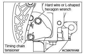
TIMING CHAIN TENSIONER REMOVAL
CAUTION
Securely install the plunger of the timing chain tensioner.
Otherwise, it may pop out.
1. Press the balancer timing chain against the timing chain tensioner, compress the plunger of the timing chain tensioner and insert hard wire (piano wire, etc.) or L-shaped hexagon wrench (1.5 mm [0.05 inch] ) to fix the plunger of the timing chain tensioner.
2. Remove the timing chain tensioner.
INSTALLATION SERVICE POINTS
CRANKSHAFT SPROCKET/BALANCER TIMING CHAIN/BALANCER SHAFT AND OIL PUMP MODULE INSTALLATION
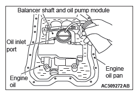
1. When installing the new balancer shaft and oil pump module, apply oil to the oil pump in the balancer shaft and oil pump module and the balancer shaft bearing as follows.
- Clean the inside of the removed engine oil pan, and put the balancer shaft and oil pump module into the engine oil pan with its oil inlet port facing up.
- Pour new engine oil until two-thirds of the balancer shaft and oil pump module is soaked.
- Fill the engine oil (approximately 50 cm3 [3.05 cu.in.] ) into the balancer shaft and oil pump module from the oil inlet port.
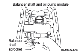
- Turn the balancer shaft sprocket of the balancer shaft and oil pump module clockwise four rotations or more to apply the engine oil to the entire area of the oil pump and the balancer shaft bearing.
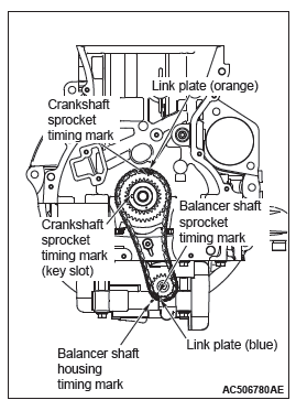
2. With the link marks (orange or blue) of balancer timing chain aligned with the timing marks of balancer sprocket and crankshaft sprocket, install the balancer shaft and oil pump module together with the balancer timing chain and crankshaft sprocket as one unit to the cylinder block. At this time, securely bring the balancer shaft and oil pump module into contact with the rudder frame mounting area.
3. Apply an adequate and minimum amount of engine oil to the threads and bearing surfaces of the balancer shaft and oil pump module bolts.
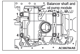
4. Tighten the balancer shaft and oil pump module bolts to the specified torque of 20 N*m (15 ft-lb) in the order of number shown in the figure.
5. Retighten the balancer shaft and oil pump module bolts to the specified torque of 44 N*m (33 ft-lb) in the order of number shown in the figure.
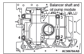
6. Loosen each balancer shaft and oil pump module bolt fully in the reverse sequence to that shown.
7. Tighten the balancer shaft and oil pump module bolts to the specified torque of 20 N*m (15 ft-lb) in the order of number shown in the figure.
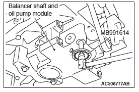
8. After tightening to the specified torque, tighten the balancer shaft and oil pump module bolts to 135 degrees, using special tool MB991614, in the order of number shown in the figure.
TIMING CHAIN TENSIONER INSTALLATION
1. Install the timing chain tensioner to the cylinder block.
2. Remove the hard wire or L-shaped hexagon wrench fixing the plunger of the timing chain tensioner to apply tension to the balancer timing chain.
READ NEXT:
 Balancer Shaft and Oil Pump Module
REMOVAL AND INSTALLATION
Pre-removal and Post-installation Operation
Engine Oil Pan Removal and Installation
Removal steps
Balancer shaft and oil pump
module
Required Special Tool:
MB991614:
Engine Assembly
REMOVAL AND INSTALLATION
CAUTION
When the engine assembly replacement is performed, use scan tool MB991958
to initialize the learning
value.
Pre-removal operation
Hood Removal
Fuel Line Pressure
Engine Overhaul - 2.4L Engine
General Specifications
Service Specifications
Rework Dimensions
Torque Specifications
NEW TIGHTENING METHOD BY USING
PLASTIC REGION TIGHTENING BOLT
Plastic region tightening bolts are used in s
SEE MORE:
Electric window control
The electric windows can only be operated with the ignition switch in the “ON”
position.
WARNING:
● Before operating the electric window control, make sure that nothing is capable
of being trapped (head, hand, finger, etc.).
● Never leave the vehicle without removing the key.
Braking
All the parts of the brake system are critical to safety. We recommend you to
have the vehicle checked at regular intervals according to the service booklet.
CAUTION:
● Avoid driving habits that cause heavy braking and never “ride” the brakes by
resting your foot on the brake pedal w
