Mitsubishi Outlander: Cylinder Head Gasket
REMOVAL AND INSTALLATION
Pre-removal operation
- Fuel Line Pressure Reduction
- Engine Room Under Cover Front B and Engine Room Side Cover (RH) Removal
- Engine Coolant Draining
- Air Cleaner Assembly Removal
- Ignition Coil Removal
- Strut Tower Bar Removal
- Exhaust Manifold Removal
- Throttle Body Assembly Removal
- EGR Valve and EGR Valve Stay Removal
- Water Pump Removal
Post-installation operation
- Water Pump Installation
- EGR Valve and EGR Valve Stay Installation
- Throttle Body Assembly Installation
- Exhaust Manifold Installation
- Strut Tower Bar Installation
- Ignition Coil Installation
- Air Cleaner Assembly Installation
- Engine Coolant Refilling
- Fuel Leak Check
- Engine Room Under Cover Front B and Engine Room Side Cover (RH) Installation
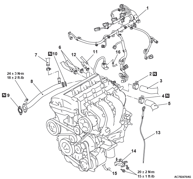
Removal steps
- Control wiring harness connection
- Hose clip
- Radiator upper hose connection
- Hose clip
- Radiator lower hose connection
- Heater hose connection
- CVT fluid cooler water return hose B connection
- Water pump intake pipe
- Cooling water line gasket
- O-ring
- Canister vacuum hose connection
- Brake booster vacuum hose connection
- Engine oil level gauge
- Intake manifold stay
- Rocker cover PCV hose connection
- Fuel high-pressure hose connection
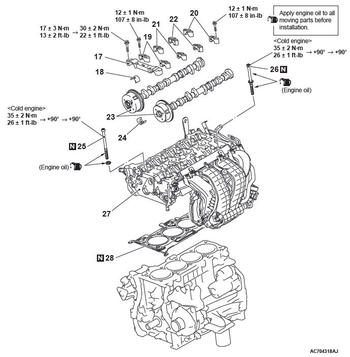
Removal steps
- Timing chain
- Front camshaft bearing cap assembly
- Camshaft bearing
- Camshaft bearing oil feeding cap
- Camshaft bearing cap
- Camshaft bearing cap
- Camshaft thrust bearing cap
- Camshaft and camshaft sprocket assembly
- Camshaft bearing
- Cylinder head bolt
- Cylinder head bolt assembly
- Cylinder head assembly
- Cylinder head gasket
Required Special Tools:
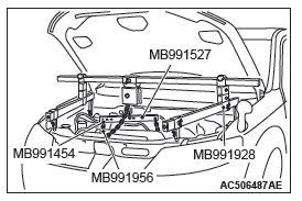
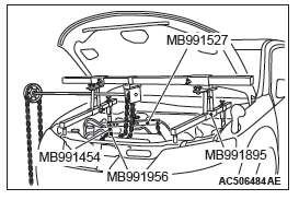
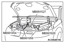
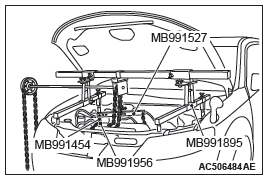
- MB991895: Engine Hanger
- MB991928: Engine Hanger
REMOVAL SERVICE POINTS
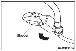
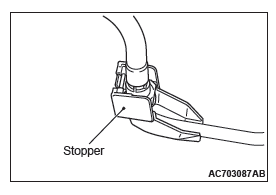
FUEL HIGH-PRESSURE HOSE REMOVAL
1. Remove the stopper of the fuel high-pressure hose.
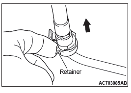
2. Raise the retainer of the fuel high-pressure hose and pull out the fuel high-pressure hose in the direction shown in the figure.
NOTE: If the retainer is released, install it securely after removing the fuel high-pressure hose.
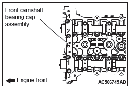
FRONT CAMSHAFT BEARING CAP ASSEMBLY REMOVAL
1. Temporarily install the engine oil pan which was removed at the valve timing chain removal.
CAUTION
When supporting the engine and transaxle assembly with a garage jack, be careful not to deform the engine oil pan.
2. Place a garage jack against the engine oil pan with a piece of wood in between to support the engine and transaxle assembly.
3. Remove special tool engine hanger (MB991928 or MB991895) which was installed for supporting the engine and transaxle assembly when the valve timing chain was removed.
CAUTION
Be careful not to drop the camshaft bearing.
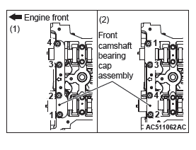
4. Loosen the mounting bolts of front camshaft bearing cap in the order of number shown in the figure, and remove the front camshaft bearing cap assembly.
CAMSHAFT BEARING OIL FEEDING CAP/CAMSHAFT BEARING CAP/CAMSHAFT BEARING THRUST CAP REMOVAL
CAUTION
When the camshaft bearing cap mounting bolts are loosened at once, the mounting bolts jump out by the spring force and the threads are damaged. Always loosen the mounting bolts in four or five steps.
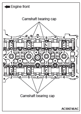
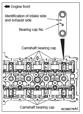
Loosen the mounting bolts of the camshaft bearing caps in the order of number shown in the figure in four or five steps, and remove the camshaft bearing caps.
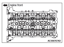
CYLINDER HEAD BOLT/CYLINDER HEAD BOLT ASSEMBLY REMOVAL
Loosen and remove the bolts in two or three steps in the order of number shown in the figure.
INSTALLATION SERVICE POINTS
CYLINDER HEAD GASKET/CYLINDER HEAD ASSEMBLY INSTALLATION
CAUTION
Do not allow any foreign materials get into the coolant passages, oil passages and cylinder.
1. Remove the sealant and grease on the top surface of cylinder block and on the bottom surface of the cylinder head. Then, use the white gasoline or the like to degrease the sealant application surface.
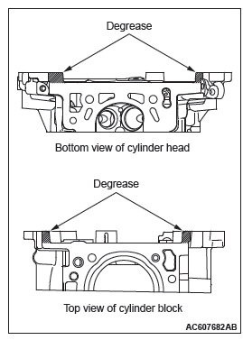
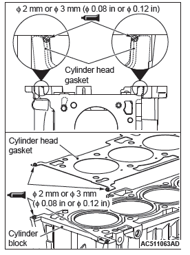
2. Apply the sealant to the top surface of cylinder block as shown in the figure.
Specified sealant: ThreeBond 1217G or equivalent
NOTE: Install the cylinder head gasket immediately after applying sealant.
3. Install the cylinder head gasket to the cylinder block.
NOTE: When the cylinder head gasket is installed to the cylinder block, check that the sealant is securely applied to the bead line of the cylinder head gasket.
4. Apply the sealant to the top surface of cylinder head gasket as shown in the figure.
Specified sealant: ThreeBond 1217G or equivalent
NOTE: Install the cylinder head assembly immediately after applying sealant.
CAUTION
After the installation, until a sufficient period of time (one hour or more) elapses, do not apply the oil or water to the sealant application area or start the engine.
5. Install the cylinder head assembly.
CYLINDER HEAD BOLT ASSEMBLY/CYLINDER HEAD BOLT INSTALLATION
1. Replace cylinder head bolts with a new ones.
2. For two cylinder head bolts of the timing chain side, the washer can be removed from the bolt. Install the washer, with its sag facing upward, to the cylinder head bolts.
3. Apply a small amount of engine oil to the cylinder head bolt threads and the washers.
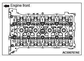
4. Tighten the cylinder head bolts by the following procedure (plastic region angular tightening method.)
- Tighten the cylinder head bolts to the specified torque in the order of number shown in the figure.
Tightening torque: 35 +- 2 N*m (26 +- 1 ft-lb)
CAUTION
- When the tightening angle is smaller than the specified tightening angle, the appropriate tightening capacity cannot be secured.
- When the tightening angle is larger than the specified tightening angle, remove the cylinder head bolt to start from the beginning again according to the procedure.
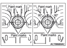
- Apply paint marks to the head of cylinder head bolt and the cylinder head.
- Tighten the cylinder head bolt to 90 degrees angle in the tightening order. Additionally tighten to 90 degrees angle, and check that the paint mark on the cylinder head bolt is aligned with the paint mark on the cylinder head.
5. Install special tool MB991928 or MB991895 which was installed for supporting the engine and transaxle assembly when the timing chain was removed.
6. Remove the garage jack which supports the engine and transaxle assembly.
7. Remove the engine oil pan installed temporarily.
CAMSHAFT BEARING/CAMSHAFT AND CAMSHAFT SPROCKET ASSEMBLY INSTALLATION
CAUTION
- Be careful not to drop the camshaft bearing.
- When installing the camshaft and camshaft sprocket assembly (exhaust side), be careful not to let the camshaft bearing which is installed to the front cam bearing deviate from its position.
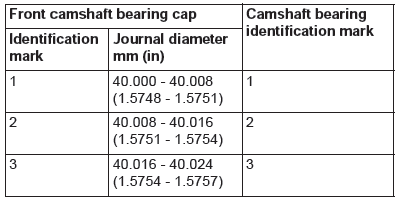
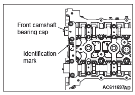
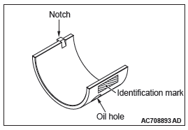
When replacing the camshaft bearing, according to the identification mark of front camshaft bearing cap in the table below, select a camshaft bearing with the corresponding size. Note that the identification mark of camshaft bearing is stamped on the place shown in the figure.
CAMSHAFT BEARING THRUST CAP/CAMSHAFT BEARING CAP/CAMSHAFT BEARING OIL FEEDING CAP INSTALLATION
1. Install the camshaft bearing caps to the cylinder heads.
NOTE: Because the camshaft bearing thrust cap and camshaft bearing cap are the same in shape, check the bearing cap number and additionally its symbol to identify the intake and exhaust sides for correct installation.
2. Tighten each camshaft bearing cap mounting bolt to the specified torque in the order of number shown in the figure in two or three steps.
Tightening torque: 12 +- 1 N*m (107 +- 8 in-lb)
FRONT CAMSHAFT BEARING CAP ASSEMBLY INSTALLATION
CAUTION
When the mounting bolts are tightened with the front camshaft bearing cap tilted, the front camshaft bearing cap is damaged. Install the front camshaft bearing cap properly to the cylinder head and camshaft.
1. Install the front camshaft bearing cap to the cylinder head, and temporarily tighten the front camshaft bearing cap to the specified torque in the order of the figure (1).
Tightening torque: 17 +- 3 N*m (13 +- 2 ft-lb)
2. Tighten the front camshaft bearing cap again to the specified torque in the order of the figure (2).
Tightening torque: 30 +- 2 N*m (22 +- 1 ft-lb)
FUEL HIGH-PRESSURE HOSE INSTALLATION
CAUTION
After connecting the fuel high-pressure hose, slightly pull it in the pull-out direction to check that it is installed firmly.
In addition, check that there is approximately 1 mm (0.04 inch) play. After the check, install the stopper securely.
READ NEXT:
 Timing Chain
REMOVAL AND INSTALLATION
Pre-removal operation
Engine Room Under Cover Front B and Engine Room
Side Cover (RH) Removal
Engine Oil Draining
Rocker Cover Assembly Removal
Engine Oil Pan Removal
Balancer Timing Chain, Balancer Shaft and Oil Pump Module
REMOVAL AND INSTALLATION
Pre-removal and Post-installation Operation
Timing Chain Removal and Installation
Removal steps
Timing chain tensioner
Balancer timing chain guide
Balancer timing chai
Balancer Shaft and Oil Pump Module
REMOVAL AND INSTALLATION
Pre-removal and Post-installation Operation
Engine Oil Pan Removal and Installation
Removal steps
Balancer shaft and oil pump
module
Required Special Tool:
MB991614:
SEE MORE:
On-vehicle Service
STEERING WHEEL FREE PLAY CHECK
1. With the engine running (hydraulic pressure applied),
position the front wheel in the straight ahead direction.
2. Measure the side to side steering wheel play until the front
wheels actually start moving while turning the steering wheel
slightly in the left and ri
Accessory socket
CAUTION:
● Be sure to use a “plug-in” type accessory operating at 12 V and at 120 W or
less.
When using more than one socket at the same time, make sure that the electrical
accessories are 12 V accessories and that the total power consumption does not exceed
120 W.
● Long us
