Mitsubishi Outlander: General Information, Diagnosis
General Information
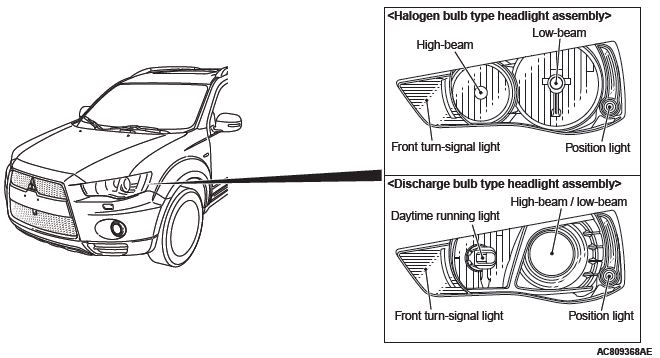
- As for headlight assembly, a type with halogen bulbs for the high-beam and low-beam and a type with a discharge bulb for both high-beam and low-beam are established.
- The halogen bulb type headlight assembly employs the four-light type integrated with the headlight (low-beam), headlight (high-beam), front turn-signal light, and position light. The dimmed headlight (low-beam) is also used as a daytime running light.
- For the discharge bulb type headlight assembly, the headlight assembly with two headlights has been adopted which incorporates the projector type headlight (low-beam/high-beam), daytime running light, front turn-signal light, and position light. Also, the headlight manual leveling system has been adopted. The switching of headlight (low-beam/high-beam) is performed by the driving of light-shield in the projector unit using the signal from lighting switch.
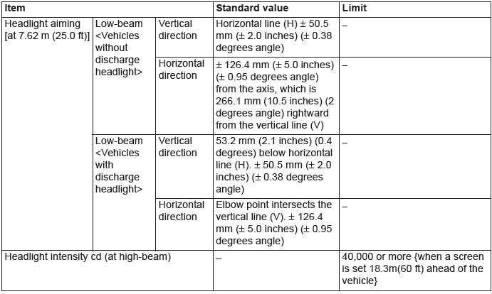
SERVICE SPECIFICATIONS
PRECAUTIONS ON HOW TO USE THE HEADLIGHT ASSEMBLY
Be careful with the following items as resin lenses are used in the headlight assembly.
- Don't illuminate the headlight for three minutes or more when the headlight is covered with scratch protector.
- Don't tape the outer lens.
- Don't scratch the outer lens surface with a sharp edged special tool.
- Use the specified genuine bulb.
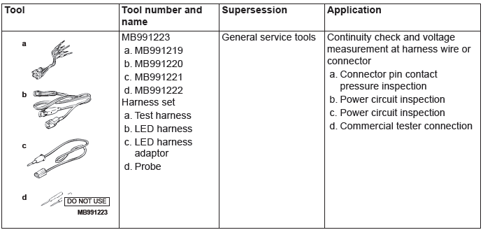
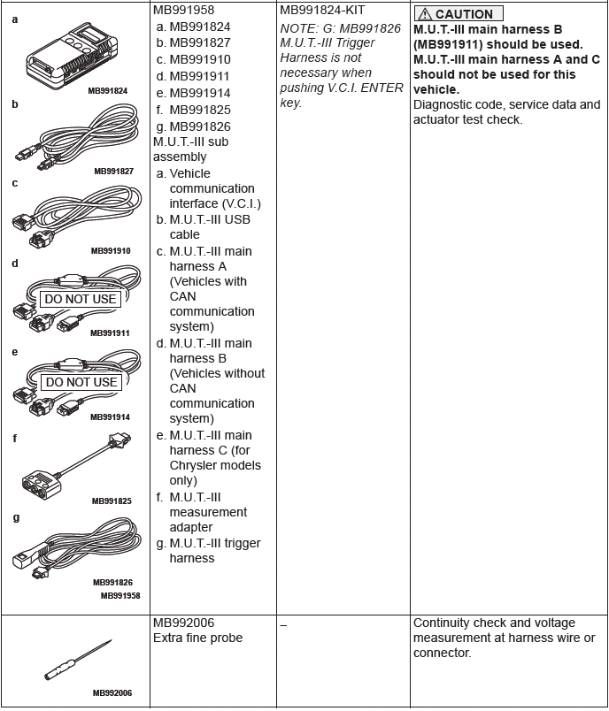
SPECIAL TOOLS
Diagnosis
STANDARD FLOW OF DIAGNOSTIC TROUBLESHOOTING
Refer to GROUP 00 − Contents of troubleshooting.
DIAGNOSTIC FUNCTION
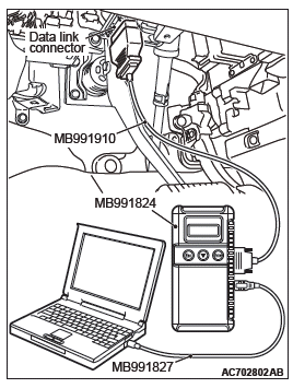
HOW TO CONNECT THE SCAN TOOL (M.U.T.-III)
Required Special Tools:
- MB991958: Scan Tool (M.U.T.-III Sub Assembly)
- MB991824: Vehicle Communication Interface (V.C.I.)
- MB991827: M.U.T.-III USB Cable
- MB991910: M.U.T.-III Main Harness A (Vehicles with CAN communication system)
CAUTION To prevent damage to scan tool MB991958, always turn the ignition switch to the "LOCK" (OFF) position before connecting or disconnecting scan tool MB991958.
1. Ensure that the ignition switch is at the "LOCK" (OFF) position.
2. Start up the personal computer.
3. Connect special tool MB991827 to special tool MB991824 and the personal computer.
4. Connect special tool MB991910 to special tool MB991824.
5. Connect special tool MB991910 to the data link connector.
6. Turn the power switch of special tool MB991824 to the "ON" position.
NOTE: When special tool MB991824 is energized, special tool MB991824 indicator light will be illuminated in a green color.
7. Start the M.U.T.-III system on the personal computer.
NOTE: Disconnecting scan tool MB991958 is the reverse of the connecting sequence, making sure that the ignition switch is at the "LOCK" (OFF) position.
HOW TO READ AND ERASE DIAGNOSTIC TROUBLE CODES
Required Special Tools:
- MB991958: Scan Tool (M.U.T.-III Sub Assembly)
- MB991824: Vehicle Communication Interface (V.C.I.)
- MB991827: M.U.T.-III USB Cable
- MB991910: M.U.T.-III Main Harness A (Vehicles with CAN communication system)
CAUTION To prevent damage to scan tool MB991958, always turn the ignition switch to the "LOCK" (OFF) position before connecting or disconnecting scan tool MB991958.
NOTE: If the battery voltage is low, diagnostic trouble codes will not be set. Check the battery if scan tool MB991958 does not display.
1. Connect scan tool MB991958 to the data link connector.
2. Turn the ignition switch to the "ON" position.
3. Select "System select" from the start-up screen.
4. Select "From 2006 MY" of "Model Year". When the "Vehicle Information" is displayed, check the contents.
5. Select "ETACS" from "System List", and press the "OK" button.
NOTE: When the "Loading Option Setup" list is displayed, check the applicable item.
6. Select "Diagnostic Trouble Code" to read the DTC.
7. If a DTC is set, it is shown.
8. Choose "Erase DTCs" to erase the DTC.
HOW TO DIAGNOSE THE CAN BUS LINES
Required Special Tools:
- MB991958: Scan Tool (M.U.T.-III Sub Assembly)
- MB991824: Vehicle Communication Interface (V.C.I.)
- MB991827: M.U.T.-III USB Cable
- MB991910: M.U.T.-III Main Harness A (Vehicles with CAN communication system)
1. Connect scan tool MB991958 to the data link connector.
2. Turn the ignition switch to the "ON" position.
3. Select "CAN bus diagnosis" from the start-up screen.
4. When the vehicle information is displayed, confirm that it matches the vehicle being diagnosed.
- If they match, go to step 8.
- If not, go to step 5.
5. Select the "view vehicle information" button.
6. Enter the vehicle information and select the "OK" button.
7. When the vehicle information is displayed, confirm again that it matches the vehicle being diagnosed.
- If they match, go to step 8.
- If not, go to step 5.
8. Select the "OK" button.
9. When the optional equipment screen is displayed, choose the one which the vehicle is fitted with, and then select the "OK" button.
SERVICE PRECAUTIONS DISCHARGE HEADLIGHT
Before checking the discharge headlight related parts, be sure to read the following warnings and precautions carefully, and then perform necessary operations.
DANGER
- Do not touch the socket and the connector
while the headlights are on. High voltage
is applied to the bulb socket and
connector during headlight operation.
The operator may be burnt or dead due to an electric shock by high voltage.
- Do not attempt to use a tester to check them. If the bulb socket and connectors should be inspected using a tester, the operator may be burnt or dead due to an electric shock by high voltage.
- Do not turn ON the headlights while the controller or the bulb is removed. If the headlights are turned ON with the controller or bulb removed, the operator may get burned by the high temperature of the bulb. The operator may be burnt or dead due to an electric shock by high voltage.
- Before service work, turn the lighting switch OFF and disconnect the battery terminal and the controller connector in a dry place. Do not touch the components with wet hands. If you work on the components with wet hands or in wet conditions, the operator may be burnt or dead due to an electric shock by high voltage.
WARNING Do not illuminate the bare headlight bulb.
(Do not illuminate the headlight using other than the vehicle power supply.) If the headlight bulb illuminates without fitting it in the headlight unit, it may burst due to rise in its internal pressure.
CAUTION When reusing the controller with the discharge headlight damaged, observe the inspection procedures for the related parts of the discharge headlight before determining the reusability of the controller. If you fail to observe "How to check discharge headlight components," the vehicle may be damaged.
1. CHECKING PROCEDURE FOR DISCHARGE HEADLIGHT RELATED PARTS (INSPECTION PROCEDURE WHEN REUSING THE CONTROLLER)
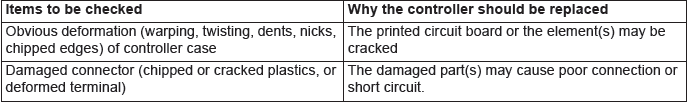
1 − 1 VISUAL CHECK OF CONTROLLER (CASE)
If any of the check items below are found, replace the controller.
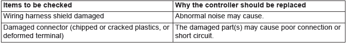
1 − 2 CHECK OF WIRING HARNESS BETWEEN CONTROLLER AND BULB
If any of the check items below are found, replace the wiring harness between the controller and the bulb.
DANGER If the wiring harness between the controller and the bulb is damaged, always replace it.
Attempting to repair the wiring harness may cause a melted harness wire, or may result in a burn or death due to an electric shock by high voltage.
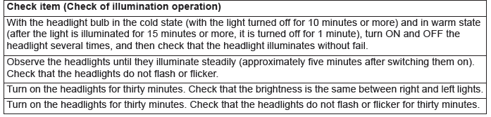
1 − 3 CHECK OF CONTROLLER OPERATION
If any of the abnormalities below are found, replace the controller.
NOTE: Ensure that the headlight control system and its circuit (power supply control at engine start and during steady illumination, high-voltage generating circuit, etc.) are working normally. Then, check whether any internal breakage has occurred in the controller. However, some internal breakage may not be found.
2. Troubleshooting procedure for discharge headlight (diagnostic procedure for malfunctions)
1. Check that the connectors are connected securely and the fuse has not been blown.
2. Before troubleshooting, read through the "Symptom chart" to understand what and how you should do. Follow all the procedures carefully.
3. The components should be checked with their connectors disconnected.
SYMPTOM CHART
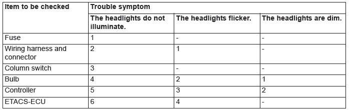
NOTE:
1. The numbers indicate the sequence in which the component is checked.
2. For the troubleshooting of other than the above, refer to Trouble Symptom Chart.
3. If ETACS-ECU fails, only the low-beam headlights will illuminate as a fail-safe measure.
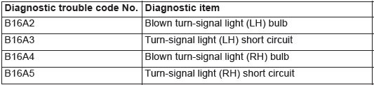
DIAGNOSTIC TROUBLE CODE CHART
CAUTION On troubleshooting, if the ignition switch is turned ON while disconnecting connector(s), diagnostic trouble code(s) associated with other system may be set. On completion, confirm all systems for diagnostic trouble code(s). If diagnostic trouble code(s) are set, erase them all.
ETACS-ECU
LIN
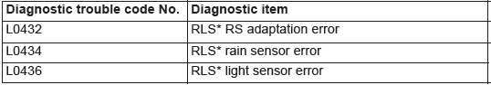
NOTE: *: Rain light sensor (Lighting control sensor)
READ NEXT:
 Diagnostic Trouble Code Procedures
DTC B16A2: Blown turn-signal light (LH) bulb
Turn-Signal Light Circuit (LH)
TROUBLE JUDGMENT
When the left bulb of turn-signal light is blown, the
ETACS-ECU sets DTC B16A2.
TECHNICAL DESCRIPTION (
Symptom Procedures
Inspection Procedure 1: None of headlights (low-beam) illuminates.
CAUTION
Whenever the ECU is replaced, ensure that the
power supply circuit, the ground circuit and the
communication circuit are norm
On-vehicle Service
HEADLIGHT AIMING
PRE-AIMING INSTRUCTIONS (LOW-BEAM)
1. Inspect for rusted or faulty headlight assemblies.
2. These conditions must be corrected before a satisfactory
adjustment can be made.
3. Insp
SEE MORE:
Safety and disposal information for usedengine oil
WARNING:
● Prolonged and repeated contact may cause serious skin disorders, including
dermatitis and cancer.
● Avoid contact with the skin as far as possible and wash thoroughly after any
contact.
● Keep used engine oils out of reach of children.
Protect the environment
It
DTC U0020, U0021, U0022, U0023, U0024, U0025, U0026, U0141, U0151, U0155, U0164,
U0168, U0184, U0195, U0245, U1419, U141A, U141B, U141C, U1423
DTC U0020: CAN-B Bus Off Performance
DTC U0021: CAN-B Bus(H1) Circuit Open
DTC U0022: CAN-B Bus(H1) Shorted to Circuit Ground
DTC U0023: CAN-B Bus(H1) Shorted to Circuit Power Supply
DTC U0024: CAN-B Bus(L0) Circuit Open
DTC U0025: CAN-B Bus(L0) Shorted to Circuit Ground
DTC U0026: CAN-B Bus(L0) Sho
