Mitsubishi Outlander: Input Signal Procedures (Central Door Locking System)
INSPECTION PROCEDURE B-1: The Liftgate Lock Release Handle Signal is not Received.
CAUTION Before replacing the ECU, ensure that the power supply circuit, the ground circuit and the communication circuit are normal.
Liftgate Lock Release Handle Circuit
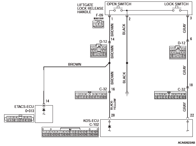
CIRCUIT OPERATION
The ETACS-ECU operates the liftgate according to signal from the liftgate lock release handle.
TECHNICAL DESCRIPTION (COMMENT)
If the signal is not normal, the liftgate will not work normally. If the signal is not normal, the liftgate lock release handle or the ETACS-ECU may be defective.
TROUBLESHOOTING HINTS
- The liftgate lock release handle may be defective
- The wiring harness or connectors may have loose, corroded, or damaged terminals, or terminals pushed back in the connector
- The ETACS-ECU may be defective
DIAGNOSTIC PROCEDURE
Required Special Tools:
- MB991223: Harness Set
- MB992006: Extra Fine Probe
- MB991958: Scan Tool (M.U.T.-III Sub Assembly)
- MB991824: Vehicles Communication Interface (V.C.I.)
- MB991827: M.U.T.-III USB Cable
- MB991910: M.U.T.-III Main Harness A
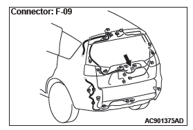
STEP 1. Check liftgate lock release handle connector F-09 for loose, corroded or damaged terminals, or terminals pushed back in the connector.
Q: Is liftgate lock release handle connector F-09 in good condition?
YES : Go to Step 2.
NO : Repair or replace the damaged component(s). Refer to GROUP 00E, Harness Connector Inspection. Repair the liftgate lock release handle. If the liftgate lock release handle operates normally, a correct signal is sent from the liftgate lock release handle.
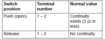
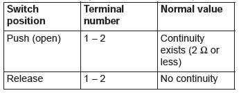
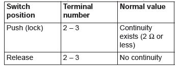
STEP 2. Check the liftgate lock release handle.
Remove the liftgate lock release handle. Refer to GROUP 42A, Liftgate Handle and Latch. Then check continuity between the switch terminals.
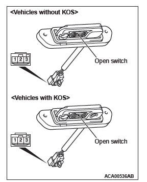
<LIFTGATE OPEN SWITCH (VEHICLES WITHOUT KOS)>
<LIFTGATE OPEN SWITCH (VEHICLES WITH KOS)>
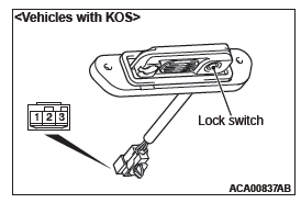
<LIFTGATE LOCK SWITCH (VEHICLES WITH KOS)>
Q: Is the liftgate lock release handle in good condition?
YES : Go to Step 3.
NO : Repair the liftgate lock release handle. If the liftgate lock release handle operates normally, a correct signal is sent from the liftgate lock release handle.
STEP 3. Check the ground circuit to the liftgate lock release handle. Measure the resistance at liftgate lock release handle connector F-09.
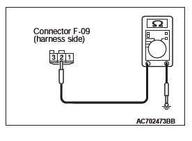
- Disconnect liftgate lock release handle connector F-09 and measure the resistance on the wiring harness side of the connector.
- Measure the resistance value between terminal 2 and ground.
- The resistance should be 2 ohms or less.
Q: Is the measured resistance 2 ohms or less?
YES : Go to Step 5.
NO : Go to Step 4.
STEP 4. Check the wiring harness between liftgate lock release handle connector F-09 (terminal 2) and ground.
- Check the power supply line for open circuit and short circuit.
Q: Is the wiring harness between liftgate lock release handle connector F-09 (terminal 2) and ground in good condition?
YES : No action is necessary and testing is complete.
NO : The wiring harness may be damaged or the connector(s) may have loose, corroded or damaged terminals, or terminals pushed back in the connector.
Repair the wiring harness as necessary. If the liftgate lock release handle operates normally, a correct signal is sent from the liftgate lock release handle.
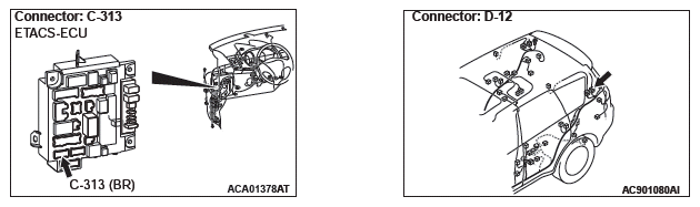
STEP 5. Check ETACS-ECU connector C-313 for loose, corroded or damaged terminals, or terminals pushed back in the connector.
Q: Is ETACS-ECU connector C-313 in good condition?
YES : Go to Step 6.
NO : Repair or replace the damaged component(s). Refer to GROUP 00E, Harness Connector Inspection. If the liftgate lock release handle operates normally, a correct signal is sent from the liftgate lock release handle.
STEP 6. Check the wiring harness between liftgate lock release handle connector F-09 (terminal 1) and ETACS-ECU connector C-313 (terminal 14).
- Check the power supply line for open circuit and short circuit.
NOTE: Also check intermediate connector D-12 for loose, corroded, or damaged terminals, or terminals pushed back in the connector. If intermediate connector D-12 is damaged, repair or replace the damaged component(s) as described in GROUP 00E, Harness Connector Inspection.
Q: Is the wiring harness between liftgate lock release handle connector F-09 (terminal 1) and ETACS-ECU connector C-313 (terminal 14) in good condition?
YES : Go to Step 7.
NO : The wiring harness may be damaged or the connector(s) may have loose, corroded or damaged terminals, or terminals pushed back in the connector.
Repair the wiring harness as necessary. If the liftgate lock release handle operates normally, a correct signal is sent from the liftgate lock release handle.
STEP 7. Using scan tool MB991958, check data list.
Check the signals related to the liftgate lock release handle operation.
CAUTION To prevent damage to scan tool MB991958, always turn the ignition switch to the "LOCK" (OFF) position before connecting or disconnecting scan tool MB991958.
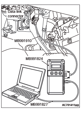
- Connect scan tool MB991958. Refer to GROUP 42B, "How to connect scan tool (M.U.T.-III)".
- Turn the ignition switch to the "ON" position.
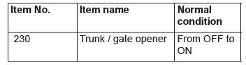
- Check the data list of the ETACS.
- Liftgate lock release handle: from OFF to ON
- Turn the ignition switch to the "LOCK" (OFF) position.
OK: Normal condition is displayed.
Q: Is the check result normal?
YES : No action is necessary and testing is complete.
NO : Replace the ETACS-ECU. If the liftgate lock release handle operates normally, a correct signal is sent from the liftgate lock release handle.
READ NEXT:
 Power Window Diagnosis
TROUBLESHOOTING STRATEGY
Refer to GROUP 00, How to Use Troubleshooting/Inspection
Service Points, Troubleshooting Contents.
DIAGNOSTIC TROUBLE CODE CHART POWER WINDOW
CAUTION
On troubleshooting, if th
Symptom Procedures (Power Window)
INSPECTION PROCEDURE C-1: Power Windows do not Work at All.
CAUTION
Before replacing the ECU, ensure that the power supply circuit, the ground
circuit and the communication
circuit are normal.
Power
Door Diagnosis
INTRODUCTION TO GLASS AND DOOR DIAGNOSIS
Glass and door faults include water leaks and
improper opening and closing. Causes for these
faults can include faults in the glass, weatherstrip,
drain hole o
SEE MORE:
Diagnostic Trouble Code Procedures
DTC B16A2: Blown turn-signal light (LH) bulb
Turn-Signal Light Circuit (LH)
TROUBLE JUDGMENT
When the left bulb of turn-signal light is blown, the
ETACS-ECU sets DTC B16A2.
TECHNICAL DESCRIPTION (COMMENT)
The ETACS-ECU sets DTC B16A2 under the following
conditions.
If there is a malfunction to
DTC B1B78, B1B79, B1B7A, B1B7D, B1B7E, B1B7F, B1B82, B1B83, B1B84, B1B87,
B1B88, B1B89, B1B8C, B1B8D, B1B8E, B1B91, B1BA7, B1BA8
DTC B1B78: Passenger Seat Weight Sensor (front: LH) Performance
DTC B1B7D: Passenger Seat Weight Sensor (front: RH) Performance
DTC B1B82: Passenger Seat Weight Sensor (rear: LH) Performance
DTC B1B87: Passenger Seat Weight Sensor (rear: RH) Performance
CAUTION
If DTC B1B78, B1B7D, B1B82 or B1B87
