Mitsubishi Outlander: Radiator
REMOVAL AND INSTALLATION <2.4L ENGINE>
Pre-removal operation
- Engine coolant Draining
- Air Cleaner Assembly Removal
Post-installation operation
- Air Cleaner Assembly Installation
- Engine Coolant Refilling and Check
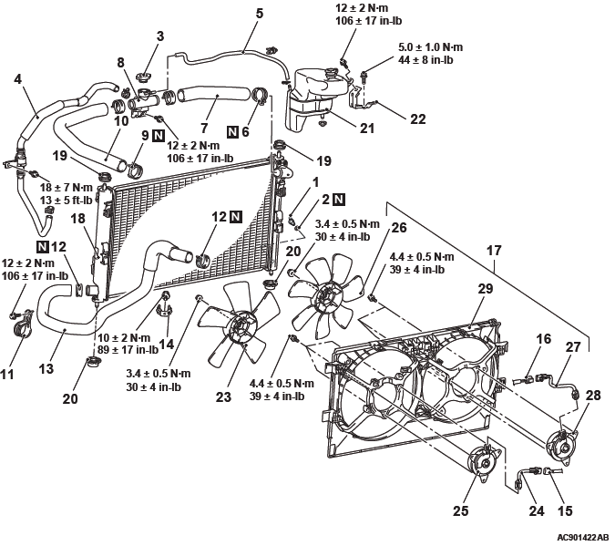
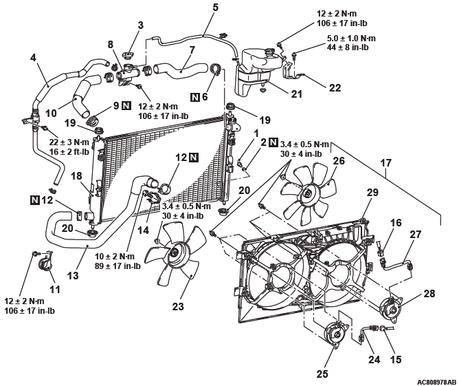
Radiator removal steps
- Engine room under cover front
- Radiator drain plug
- O-ring
- Radiator cap
- CVT fluid cooler feed hose assembly
- Radiator condenser tank hose
- Hose clip
- Radiator upper hose
- Radiator cap assembly
- Hose clip
- Radiator upper hose
- Radiator hose clamp
- Hose clip
- Radiator lower hose
- Radiator hose support
- Radiator fan motor connector
- Condenser fan motor connector
- Fan, fan motor and fan shroud assembly
- Headlight support upper panel
- Radiator assembly
- Support upper insulator
- Support lower insulator
- Radiator condenser tank
- Radiator condenser tank bracket
Fan shroud removal steps
- CVT fluid cooler feed hose assembly
- Radiator condenser tank hose
- Hose clip
- Radiator upper hose
- Radiator cap assembly
- Radiator fan motor connector
- Condenser fan motor connector
- Fan, fan motor and fan shroud assembly
- Radiator fan
- Radiator fan motor harness
- Radiator fan motor
- Condenser fan
- Condenser fan motor harness
- Condenser fan motor
- Fan shroud
REMOVAL SERVICE POINT
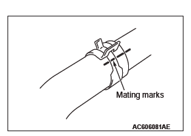
HOSE CLIP/RADIATOR HOSE REMOVAL
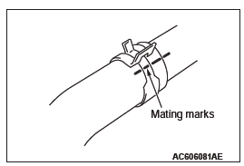
1. Make mating marks on the radiator hose and the hose clip as shown to install them in the original position.
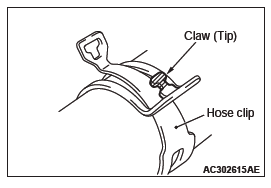
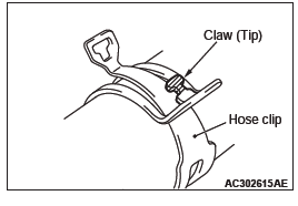
2. Break off the tip of hose clip claw and spread out the hose clip, then disconnect the radiator hose.
NOTE: If there is a hose clip claw, the hose clip cannot spread to capacity because the claw contacts the hose clip.
INSTALLATION SERVICE POINT
RADIATOR HOSE/HOSE CLIP INSTALLATION
CAUTION
Never reuse the hose clip whose claw is broken off to prevent the rusting.
1. Make mating mark on a new hose clip in the same position as the remove one.
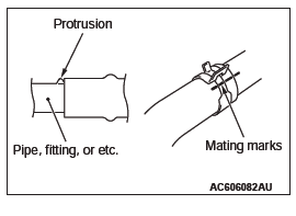
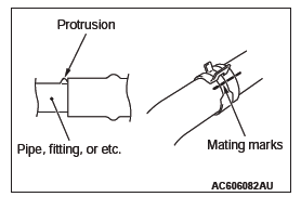
2. Insert the radiator hose until the protrusion of the pipe.
3. Align the mating marks on the radiator hose and hose clip.
4. Remove the hose clip claw and shorten the hose clip, then install the radiator hose.
REMOVAL AND INSTALLATION <3.0L ENGINE>
Pre-removal operation
- Engine coolant Draining
- Air Cleaner Assembly Removal
Post-installation operation
- Air Cleaner Assembly Installation
- Engine Coolant Refilling and Check
Radiator removal steps
- Engine room under cover front
- Radiator drain plug
- O-ring
- Radiator cap
- A/T fluid cooler feed hose assembly
- Radiator condenser tank hose
- Hose clip
- Radiator upper hose
- Radiator cap assembly
- Hose clip
- Radiator upper hose
- Radiator hose clamp
- Hose clip
- Radiator lower hose
- Radiator hose support
- Radiator fan motor connector
- Condenser fan motor connector
- Fan, fan motor and fan shroud assembly
- Headlight support upper panel
- Radiator assembly
- Support upper insulator
- Support lower insulator
- Radiator condenser tank
- Radiator condenser tank bracket
Fan shroud removal steps
- Radiator condenser tank hose
- Hose clip
- Radiator upper hose
- Radiator cap assembly
- Radiator fan motor connector
- Condenser fan motor connector
- Fan, fan motor and fan shroud assembly
- Radiator fan
- Radiator fan motor harness
- Radiator fan motor
- Condenser fan
- Condenser fan motor harness
- Condenser fan motor
- Fan shroud
REMOVAL SERVICE POINT
HOSE CLIP/RADIATOR HOSE REMOVAL
1. Make mating marks on the radiator hose and the hose clip as shown to install them in the original position.
2. Break off the tip of hose clip claw and spread out the hose clip, then disconnect the radiator hose.
NOTE: If there is a hose clip claw, the hose clip cannot spread to capacity because the claw contacts the hose clip.
INSTALLATION SERVICE POINT
RADIATOR HOSE/HOSE CLIP INSTALLATION
CAUTION
Never reuse the hose clip whose claw is broken off to prevent the rusting.
1. Make mating mark on a new hose clip in the same position as the remove one.
2. Insert the radiator hose until the protrusion of the pipe.
3. Align the mating marks on the radiator hose and hose clip.
4. Remove the hose clip claw and shorten the hose clip, then install the radiator hose.
READ NEXT:
 Charging System
GENERAL INFORMATION
The charging system charges the battery with the
generator output to keep the battery charged at a
constant level during varying electrical load.
OPERATION
Rotation of the excited
Starting System
GENERAL INFORMATION
If the ignition switch is turned to the "START" position,
current flows in the coil provided inside magnetic
switch, attracting the plunger. When the plunger
is attracted, the lev
SEE MORE:
DTC No.C100A, C1015, C1020, C102B, C1011, C101C, C1027, C1032,
C1014, C101F, C102A, C1035, C1078, C1219, C121A, C123C, C1242, C145F, C1460,
C1610, C1614, C1616
Code No.C100A <FL>, C1015 <FR>, C1020 <RL>, C102B <RR>: Wheel Speed
Sensor System (Faulty
Circuit)
CAUTION
If there is any problem in the CAN bus lines,
an incorrect diagnostic trouble code may be
set. Prior to this diagnosis, diagnose the CAN
bus lines.
Whenever the E
Bottle holder
CAUTION:
● Do not drink beverages while driving. This is distracting and could cause an
accident.
● Drinks could be spilled by the vibration and jolts while driving. If the spilt
drink is very hot, you could be burnt.
NOTE:
● Tightly close the cap on drink bottles before st
