Mitsubishi Outlander: Steering Column Shaft Assembly
REMOVAL AND INSTALLATION
CAUTION
- Before removing the steering wheel/driver's air bag module assembly, refer to GROUP 52B − Service Precautions and Driver's Air Bag Module Clock Spring.
- After the installation, perform a calibration for the ASC-ECU to learn the steering wheel sensor neutral point. (Refer to GROUP 35C − On-vehicle Service − Steering Wheel Sensor Calibration). <Vehicles with ASC>
Pre-removal operation
- Driver's Air Bag Module and Steering Wheel Assembly Removal
- Bottom Cover Assembly (Driver's seat) and Side Lower Panel Assembly Removal
- Lower side cover (L) Removal
- WCM vehicles with WCM/Receiver Antenna Module vehicles with KOS Removal
Post-installation operation
- WCM vehicles with WCM/Receiver Antenna Module vehicles with KOS Installation
- Lower side cover (L) Installation
- Bottom Cover Assembly (Driver's seat) and Side Lower Panel Assembly Installation
- Driver's Air Bag Module and Steering Wheel Assembly Installation
- Confirm that the steering wheel is at the straight-ahead position
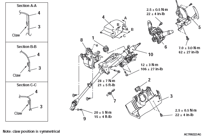
Removal steps
- Knob cap <Vehicles with KOS>
- Ignition key cover
- Steering column lower cover
- Steering column upper cover
- Paddle shift assembly <Vehicles with paddle shift>
- Clock spring column switch assembly
- Key interlock cable <Refer to GROUP 23A - CVT Key Interlock And Shiftlock Mechanisms (CVT), Refer to GROUP 23C - A/T Key Interlock And Shiftlock Mechanisms (A/T)>.
- Steering shaft cover
- Steering column bolt (steering column shaft assembly and steering gear and linkage connection)
- Steering column shaft assembly
REMOVAL SERVICE POINTS
KNOB CAP REMOVAL
Remove the knob cap while pressing the two projections.
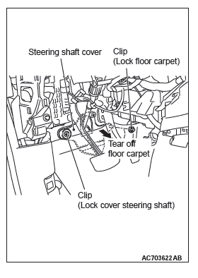
STEERING SHAFT COVER REMOVAL
1. Remove the clip (for securing the floor carpet), and turn back the floor carpet.
2. Remove the clip (for securing the steering shaft cover), and then remove the steering shaft cover.
STEERING COLUMN SHAFT ASSEMBLY REMOVAL
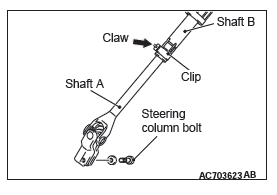
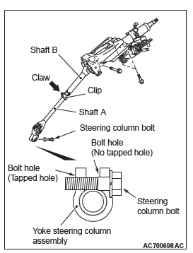
1. Remove the steering column bolt connecting the steering gear to the steering column assembly.
2. Disconnect the steering gear from the steering column assembly while sliding the shaft A to the shaft B with the clip claw as shown in the figure is pinched.
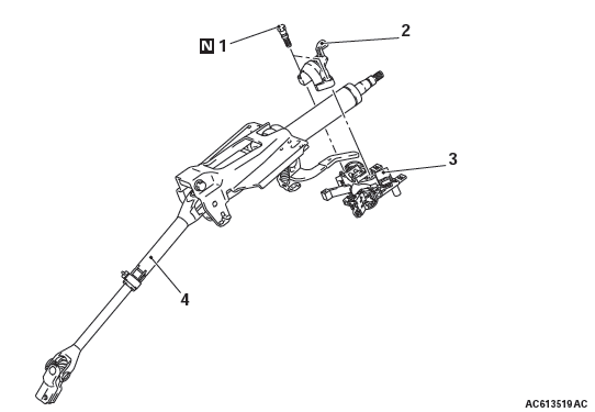
3. Remove the steering column mounting bolt.
INSTALLATION SERVICE POINTS
STEERING COLUMN SHAFT ASSEMBLY INSTALLATION
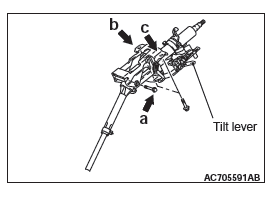
1. Ensure that the tilt lever is in the lock position.
2. Temporarily tighten the mounting bolts in the order of a, b, and c, and then tighten them in the order of c, b, and a to the specified torque.
Tightening torque a: 28 +- 7 N*m (21 +- 5 ft-lb)
Tightening torque b,c: 12 +- 3 N*m (106 +- 26 in-lb)
STEERING COLUMN BOLT (STEERING COLUMN SHAFT ASSEMBLY AND STEERING GEAR & LINKAGE CONNECTION) INSTALLATION
1. While sliding shaft A from shaft B with the clip claw as shown in the figure being pinched, connect the steering column shaft assembly and the steering gear and linkage.
2. Insert the steering column bolt from the no tapped bolt hole, and tighten it to the specified torque.
Tightening torque : 20 +- 5 N*m (15 +- 3 ft-lb)
DISASSEMBLY AND ASSEMBLY
Disassembly steps
- Steering lock bolt
- Steering lock bracket
- Steering lock cylinder assembly
- Steering column shaft assembly
DISASSEMBLY SERVICE POINT
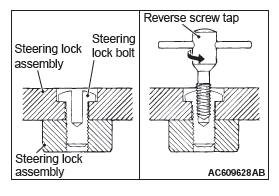
STEERING LOCK BOLT REMOVAL
1. Use a drill to make a hole just deeply enough for the tap to stand on the steering lock bolt.
2. Use a left-hand thread tap to remove the steering lock bolt.
ASSEMBLY SERVICE POINT
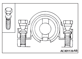
STEERING LOCK CYLINDER ASSEMBLY/ STEERING LOCK BRACKET/STEERING LOCK BOLT INSTALLATION
1. When installing the steering lock assembly to the steering column shaft assembly, temporarily assemble the steering lock assembly while aligning it with the boss on the column.
2. Make sure that the steering lock operates normally, and then tighten evenly the both steering lock bolt until their head are broken off.
READ NEXT:
 Power Steering Gear Box and Linkage
REMOVAL AND INSTALLATION
CAUTION
Before removing the steering wheel and driver's airbag module, refer
to GROUP 52B − Service
Precautions and Driver's Airbag Module and Clock Spring. Positio
Power Steering Oil Pump
Assembly
REMOVAL AND INSTALLATION
Pre-removal operation
Power Steering Fluid Draining
Engine Upper Cover Removal
Engine Room Side Cover (RH) Removal
Generator and Others Belt Removal
Post-installation
Power Steering Hoses
REMOVAL AND INSTALLATION
Pre-removal operation
Power Steering Fluid Draining
Engine room Under Cover Front (A,B,C), Engine room
Side Cover, Engine room Under Cover Rear Removal
Propeller Shaft A
SEE MORE:
General Information
NOTE: In this manual, F.A.S.T.-key (Free-hand
Advanced Security Transmitter) is described as Keyless
Operation System (KOS).
The keyless operation system (KOS) enables the
driver to unlock all the doors and the liftgate by just
pulling the front door outside handle or operating the
liftgate lock rel
On-vehicle Service
STEERING WHEEL FREE PLAY CHECK
1. With the engine running (hydraulic pressure applied),
position the front wheel in the straight ahead direction.
2. Measure the side to side steering wheel play until the front
wheels actually start moving while turning the steering wheel
slightly in the left and ri
